Jack SUBARU LEGACY 1995 Service Service Manual
[x] Cancel search | Manufacturer: SUBARU, Model Year: 1995, Model line: LEGACY, Model: SUBARU LEGACY 1995Pages: 2248, PDF Size: 48.81 MB
Page 606 of 2248
5. Replacement of Front DOJ and UFJ
Boots
A: REMOVAL
1) Disconnect ground cable from battery.
2) Jack-up vehicle, support it with safety stands (rigid
rocks), and remove front wheel cap and wheels.
NOTE:
Do not remove axle nut.
3) Remove stabilizer link.
4) Disconnect transverse link from housing.
G4M0279
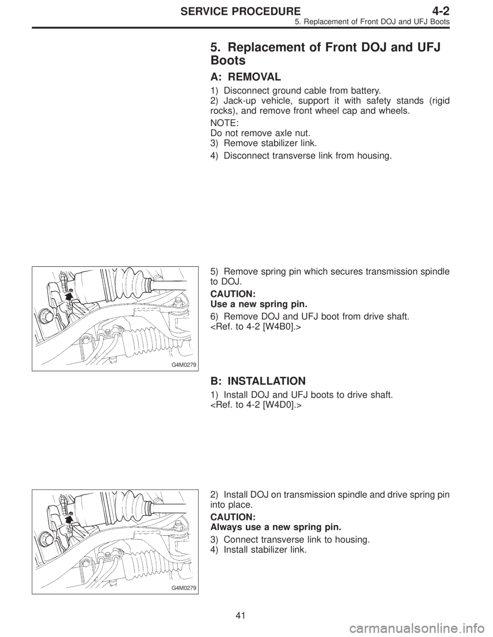
5) Remove spring pin which secures transmission spindle
to DOJ.
CAUTION:
Use a new spring pin.
6) Remove DOJ and UFJ boot from drive shaft.
B: INSTALLATION
1) Install DOJ and UFJ boots to drive shaft.
G4M0279
2) Install DOJ on transmission spindle and drive spring pin
into place.
CAUTION:
Always use a new spring pin.
3) Connect transverse link to housing.
4) Install stabilizer link.
41
4-2SERVICE PROCEDURE
5. Replacement of Front DOJ and UFJ Boots
Page 611 of 2248
G4M0298
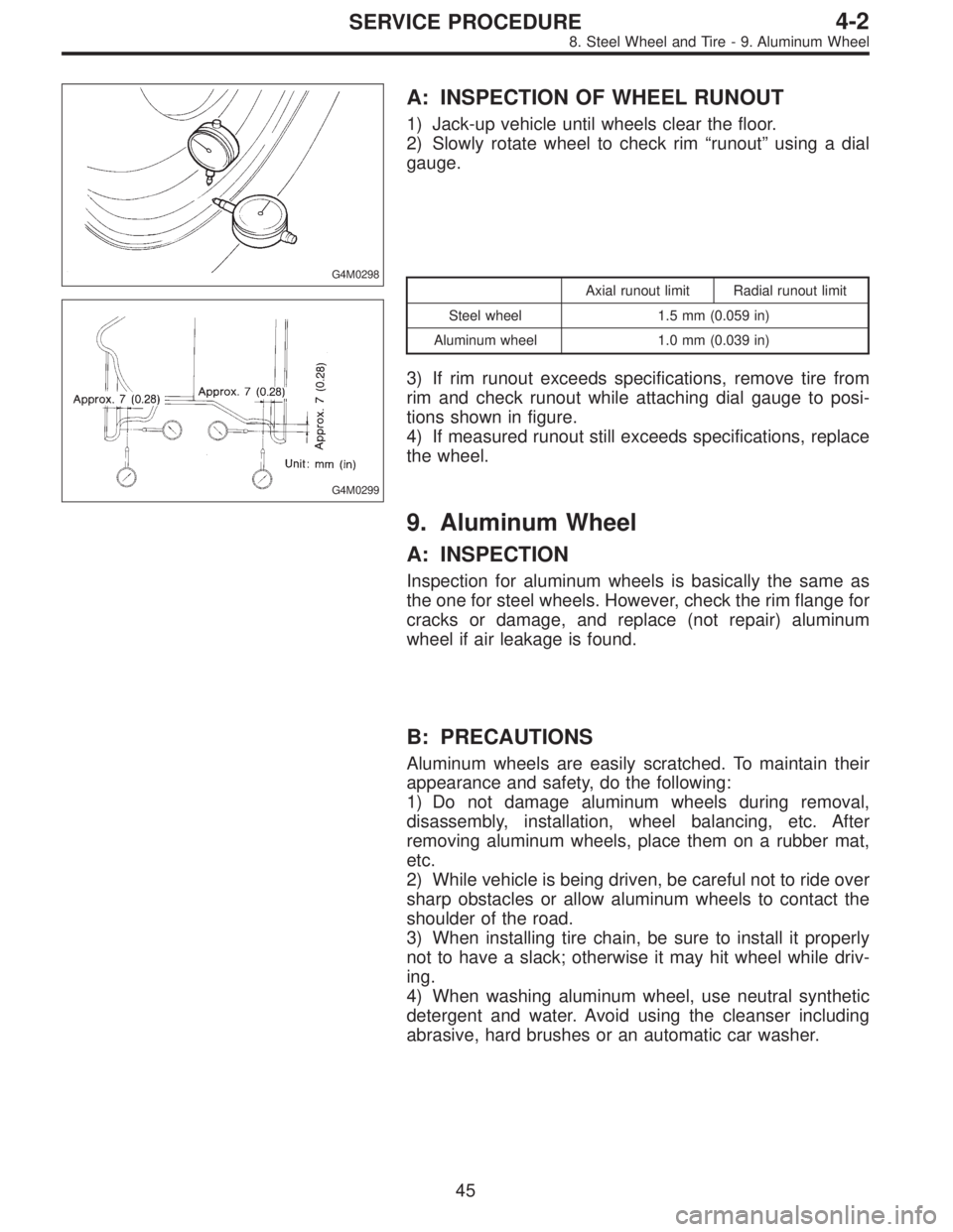
A: INSPECTION OF WHEEL RUNOUT
1) Jack-up vehicle until wheels clear the floor.
2) Slowly rotate wheel to check rim“runout”using a dial
gauge.
G4M0299
Axial runout limit Radial runout limit
Steel wheel 1.5 mm (0.059 in)
Aluminum wheel 1.0 mm (0.039 in)
3) If rim runout exceeds specifications, remove tire from
rim and check runout while attaching dial gauge to posi-
tions shown in figure.
4) If measured runout still exceeds specifications, replace
the wheel.
9. Aluminum Wheel
A: INSPECTION
Inspection for aluminum wheels is basically the same as
the one for steel wheels. However, check the rim flange for
cracks or damage, and replace (not repair) aluminum
wheel if air leakage is found.
B: PRECAUTIONS
Aluminum wheels are easily scratched. To maintain their
appearance and safety, do the following:
1) Do not damage aluminum wheels during removal,
disassembly, installation, wheel balancing, etc. After
removing aluminum wheels, place them on a rubber mat,
etc.
2) While vehicle is being driven, be careful not to ride over
sharp obstacles or allow aluminum wheels to contact the
shoulder of the road.
3) When installing tire chain, be sure to install it properly
not to have a slack; otherwise it may hit wheel while driv-
ing.
4) When washing aluminum wheel, use neutral synthetic
detergent and water. Avoid using the cleanser including
abrasive, hard brushes or an automatic car washer.
45
4-2SERVICE PROCEDURE
8. Steel Wheel and Tire - 9. Aluminum Wheel
Page 612 of 2248
G4M0298
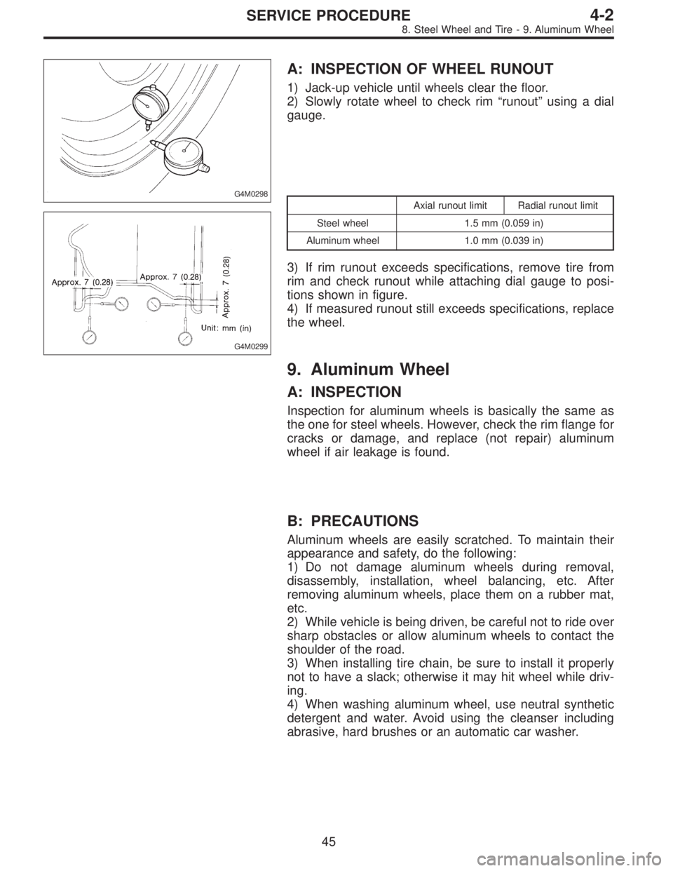
A: INSPECTION OF WHEEL RUNOUT
1) Jack-up vehicle until wheels clear the floor.
2) Slowly rotate wheel to check rim“runout”using a dial
gauge.
G4M0299
Axial runout limit Radial runout limit
Steel wheel 1.5 mm (0.059 in)
Aluminum wheel 1.0 mm (0.039 in)
3) If rim runout exceeds specifications, remove tire from
rim and check runout while attaching dial gauge to posi-
tions shown in figure.
4) If measured runout still exceeds specifications, replace
the wheel.
9. Aluminum Wheel
A: INSPECTION
Inspection for aluminum wheels is basically the same as
the one for steel wheels. However, check the rim flange for
cracks or damage, and replace (not repair) aluminum
wheel if air leakage is found.
B: PRECAUTIONS
Aluminum wheels are easily scratched. To maintain their
appearance and safety, do the following:
1) Do not damage aluminum wheels during removal,
disassembly, installation, wheel balancing, etc. After
removing aluminum wheels, place them on a rubber mat,
etc.
2) While vehicle is being driven, be careful not to ride over
sharp obstacles or allow aluminum wheels to contact the
shoulder of the road.
3) When installing tire chain, be sure to install it properly
not to have a slack; otherwise it may hit wheel while driv-
ing.
4) When washing aluminum wheel, use neutral synthetic
detergent and water. Avoid using the cleanser including
abrasive, hard brushes or an automatic car washer.
45
4-2SERVICE PROCEDURE
8. Steel Wheel and Tire - 9. Aluminum Wheel
Page 632 of 2248
A: REMOVAL
1) Disconnect battery minus terminal.
2) Loosen front wheel nut.
3) Lift vehicle and remove front wheels.
4) Remove front exhaust pipe assembly.
WARNING:
Be careful, exhaust pipe is hot.
G4M0097
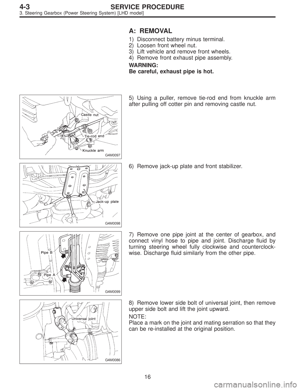
5) Using a puller, remove tie-rod end from knuckle arm
after pulling off cotter pin and removing castle nut.
G4M0098
6) Remove jack-up plate and front stabilizer.
G4M0099
7) Remove one pipe joint at the center of gearbox, and
connect vinyl hose to pipe and joint. Discharge fluid by
turning steering wheel fully clockwise and counterclock-
wise. Discharge fluid similarly from the other pipe.
G4M0086
8) Remove lower side bolt of universal joint, then remove
upper side bolt and lift the joint upward.
NOTE:
Place a mark on the joint and mating serration so that they
can be re-installed at the original position.
16
4-3SERVICE PROCEDURE
3. Steering Gearbox (Power Steering System) [LHD model]
Page 642 of 2248
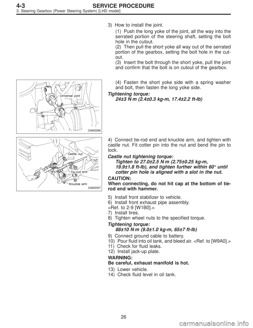
3) How to install the joint.
(1) Push the long yoke of the joint, all the way into the
serrated portion of the steering shaft, setting the bolt
hole in the cutout.
(2) Then pull the short yoke all way out of the serrated
portion of the gearbox, setting the bolt hole in the cut-
out.
(3) Insert the bolt through the short yoke, pull the joint
and confirm that the bolt is on cutout of the gearbox.
G4M0086
(4) Fasten the short yoke side with a spring washer
and bolt, then fasten the long yoke side.
Tightening torque:
24±3 N⋅m (2.4±0.3 kg-m, 17.4±2.2 ft-lb)
G4M0097
4) Connect tie-rod end and knuckle arm, and tighten with
castle nut. Fit cotter pin into the nut and bend the pin to
lock.
Castle nut tightening torque:
Tighten to 27.0±2.5 N⋅m (2.75±0.25 kg-m,
19.9±1.8 ft-lb), and tighten further within 60°until
cotter pin hole is aligned with a slot in the nut.
CAUTION:
When connecting, do not hit cap at the bottom of tie-
rod end with hammer.
5) Install front stabilizer to vehicle.
6) Install front exhaust pipe assembly.
7) Install tires.
8) Tighten wheel nuts to the specified torque.
Tightening torque:
88±10 N⋅m (9.0±1.0 kg-m, 65±7 ft-lb)
9) Connect ground cable to battery.
10) Pour fluid into oil tank, and bleed air.
11) Check for fluid leaks.
12) Install jack-up plate.
WARNING:
Be careful, exhaust manifold is hot.
13) Lower vehicle.
14) Check fluid level in oil tank.
26
4-3SERVICE PROCEDURE
3. Steering Gearbox (Power Steering System) [LHD model]
Page 646 of 2248
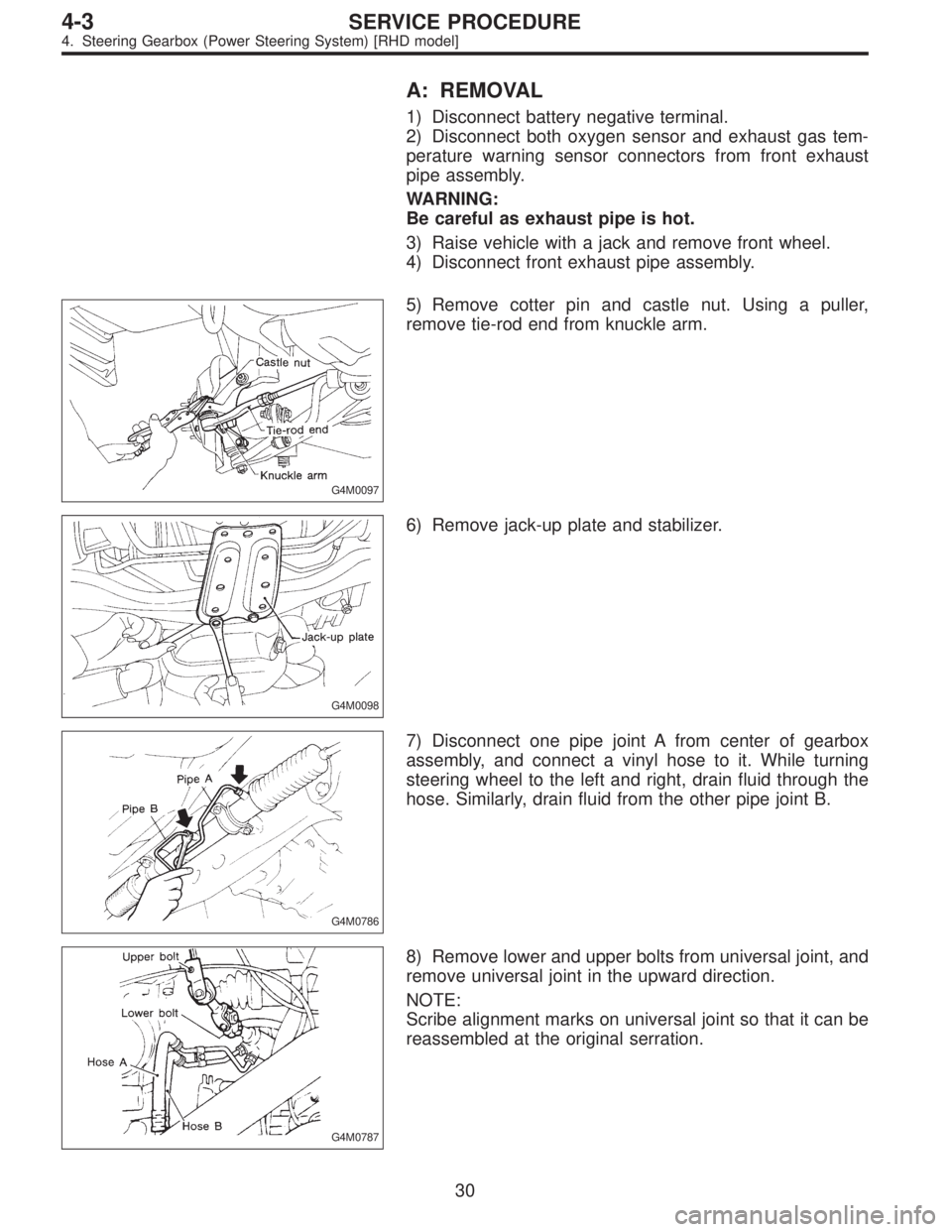
A: REMOVAL
1) Disconnect battery negative terminal.
2) Disconnect both oxygen sensor and exhaust gas tem-
perature warning sensor connectors from front exhaust
pipe assembly.
WARNING:
Be careful as exhaust pipe is hot.
3) Raise vehicle with a jack and remove front wheel.
4) Disconnect front exhaust pipe assembly.
G4M0097
5) Remove cotter pin and castle nut. Using a puller,
remove tie-rod end from knuckle arm.
G4M0098
6) Remove jack-up plate and stabilizer.
G4M0786
7) Disconnect one pipe joint A from center of gearbox
assembly, and connect a vinyl hose to it. While turning
steering wheel to the left and right, drain fluid through the
hose. Similarly, drain fluid from the other pipe joint B.
G4M0787
8) Remove lower and upper bolts from universal joint, and
remove universal joint in the upward direction.
NOTE:
Scribe alignment marks on universal joint so that it can be
reassembled at the original serration.
30
4-3SERVICE PROCEDURE
4. Steering Gearbox (Power Steering System) [RHD model]
Page 678 of 2248
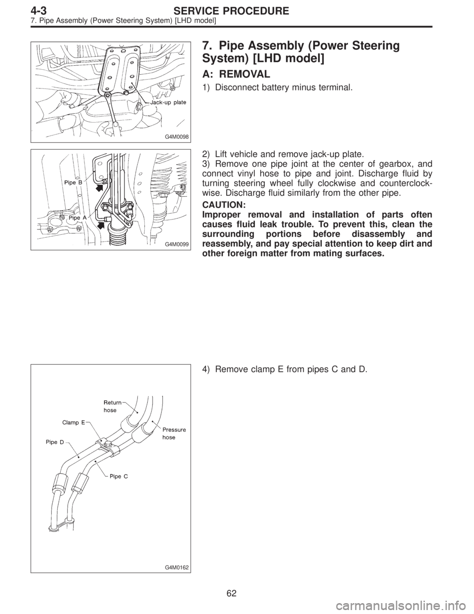
G4M0098
7. Pipe Assembly (Power Steering
System) [LHD model]
A: REMOVAL
1) Disconnect battery minus terminal.
G4M0099
2) Lift vehicle and remove jack-up plate.
3) Remove one pipe joint at the center of gearbox, and
connect vinyl hose to pipe and joint. Discharge fluid by
turning steering wheel fully clockwise and counterclock-
wise. Discharge fluid similarly from the other pipe.
CAUTION:
Improper removal and installation of parts often
causes fluid leak trouble. To prevent this, clean the
surrounding portions before disassembly and
reassembly, and pay special attention to keep dirt and
other foreign matter from mating surfaces.
G4M0162
4) Remove clamp E from pipes C and D.
62
4-3SERVICE PROCEDURE
7. Pipe Assembly (Power Steering System) [LHD model]
Page 681 of 2248
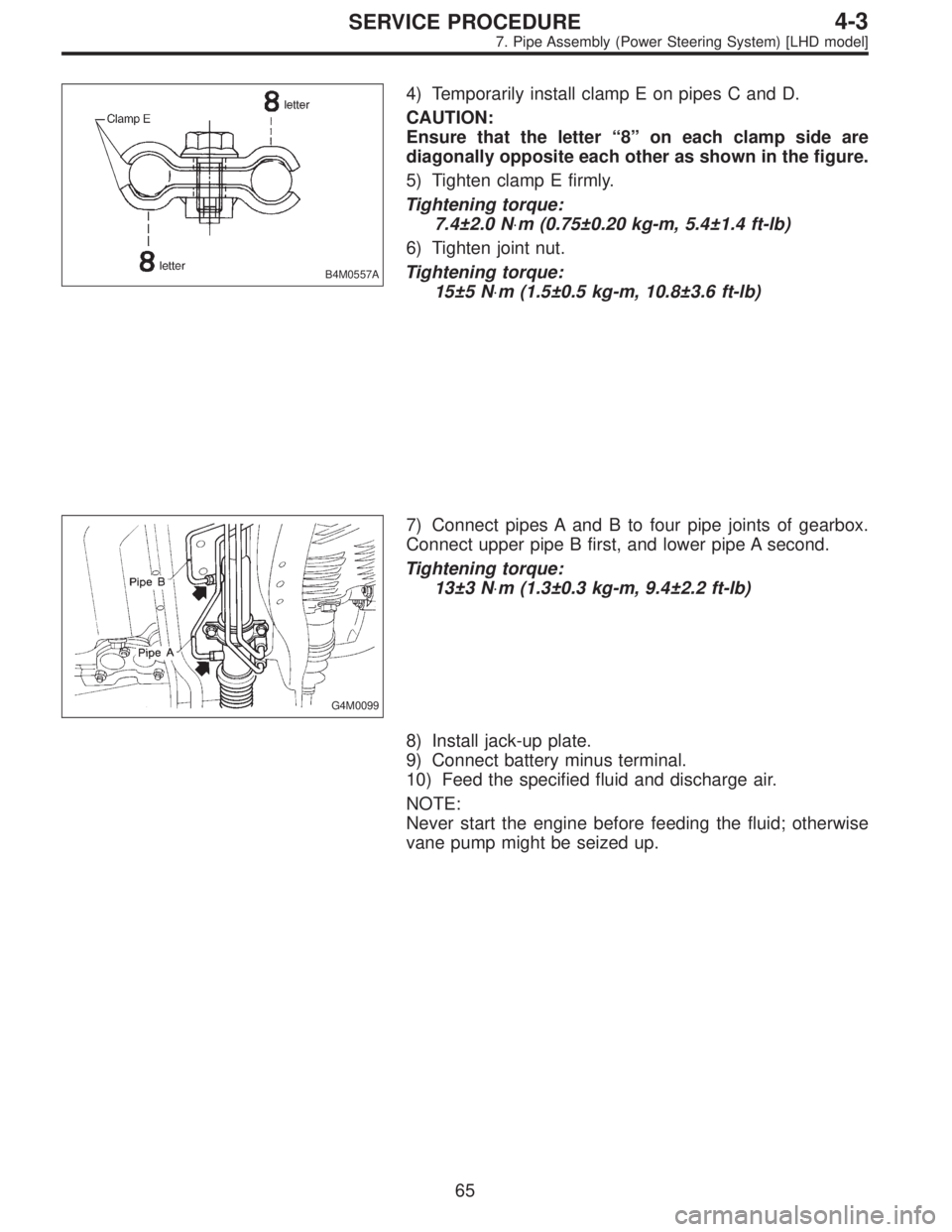
B4M0557A
4) Temporarily install clamp E on pipes C and D.
CAUTION:
Ensure that the letter“8”on each clamp side are
diagonally opposite each other as shown in the figure.
5) Tighten clamp E firmly.
Tightening torque:
7.4±2.0 N⋅m (0.75±0.20 kg-m, 5.4±1.4 ft-lb)
6) Tighten joint nut.
Tightening torque:
15±5 N⋅m (1.5±0.5 kg-m, 10.8±3.6 ft-lb)
G4M0099
7) Connect pipes A and B to four pipe joints of gearbox.
Connect upper pipe B first, and lower pipe A second.
Tightening torque:
13±3 N⋅m (1.3±0.3 kg-m, 9.4±2.2 ft-lb)
8) Install jack-up plate.
9) Connect battery minus terminal.
10) Feed the specified fluid and discharge air.
NOTE:
Never start the engine before feeding the fluid; otherwise
vane pump might be seized up.
65
4-3SERVICE PROCEDURE
7. Pipe Assembly (Power Steering System) [LHD model]
Page 683 of 2248
G4M0098
8. Pipe Assembly (Power Steering
System) [RHD model]
A: REMOVAL
1) Disconnect battery negative terminal.
B4M0671A
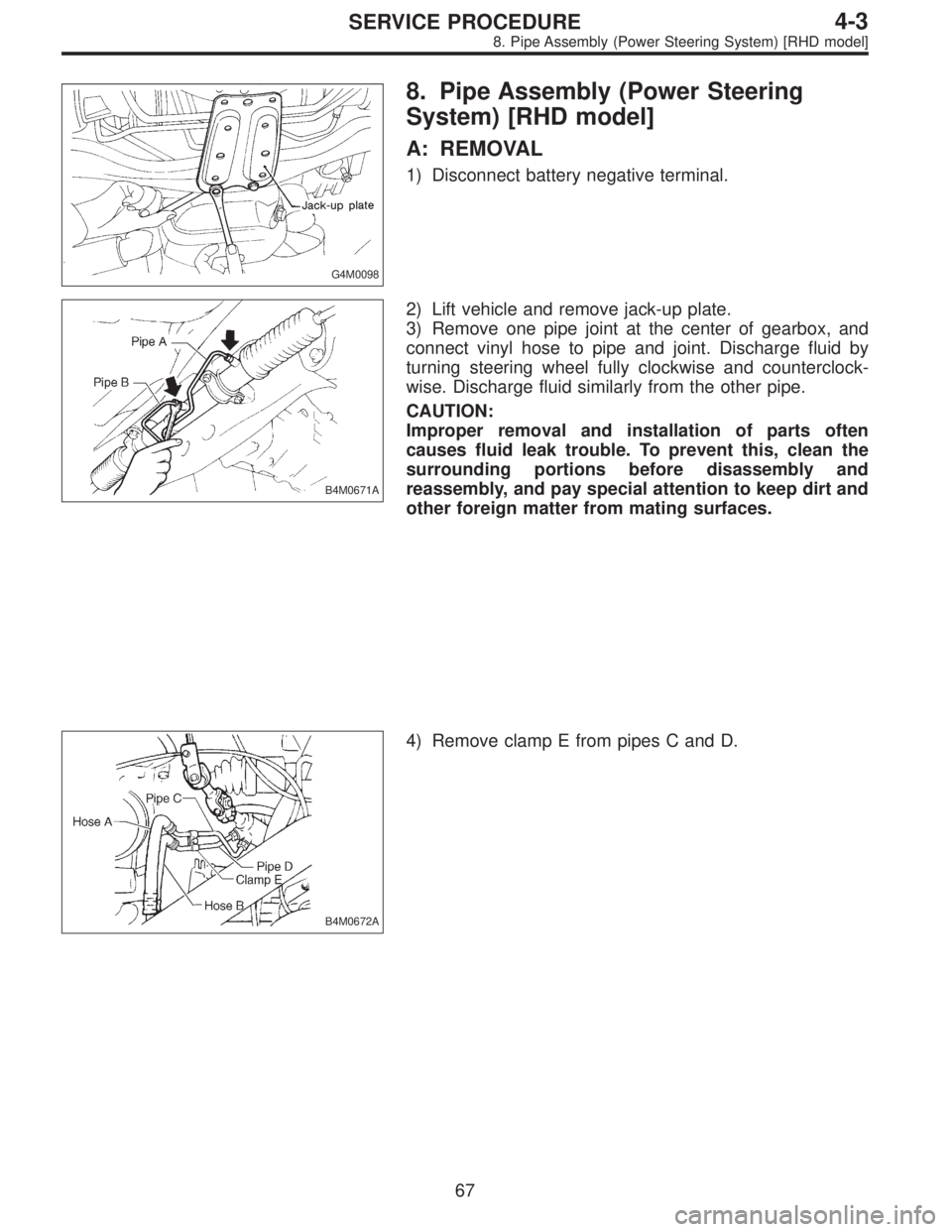
2) Lift vehicle and remove jack-up plate.
3) Remove one pipe joint at the center of gearbox, and
connect vinyl hose to pipe and joint. Discharge fluid by
turning steering wheel fully clockwise and counterclock-
wise. Discharge fluid similarly from the other pipe.
CAUTION:
Improper removal and installation of parts often
causes fluid leak trouble. To prevent this, clean the
surrounding portions before disassembly and
reassembly, and pay special attention to keep dirt and
other foreign matter from mating surfaces.
B4M0672A
4) Remove clamp E from pipes C and D.
67
4-3SERVICE PROCEDURE
8. Pipe Assembly (Power Steering System) [RHD model]
Page 686 of 2248
B4M0671A
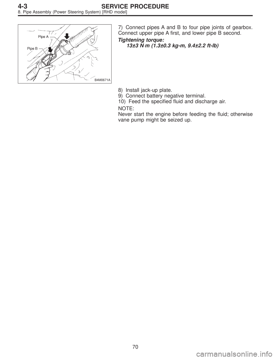
7) Connect pipes A and B to four pipe joints of gearbox.
Connect upper pipe A first, and lower pipe B second.
Tightening torque:
13±3 N⋅m (1.3±0.3 kg-m, 9.4±2.2 ft-lb)
8) Install jack-up plate.
9) Connect battery negative terminal.
10) Feed the specified fluid and discharge air.
NOTE:
Never start the engine before feeding the fluid; otherwise
vane pump might be seized up.
70
4-3SERVICE PROCEDURE
8. Pipe Assembly (Power Steering System) [RHD model]