Hose SUBARU LEGACY 1996 Service Repair Manual
[x] Cancel search | Manufacturer: SUBARU, Model Year: 1996, Model line: LEGACY, Model: SUBARU LEGACY 1996Pages: 2890, PDF Size: 61.9 MB
Page 4 of 2890
2-1
IM9-0)
EMISSION
CONTROL
SYSTEM
AND
VACUUM
FITTING
9
.
Vacuum
Fitting
9
.
Vacuum
Fitting
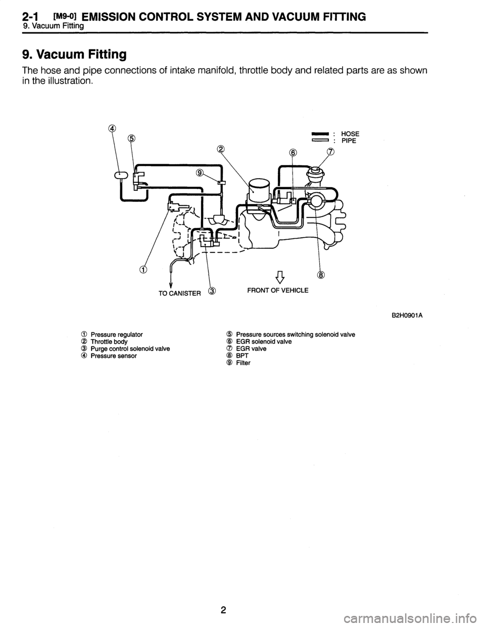
The
hose
and
pipe
connections
of
intake
manifold,
throttle
body
and
related
parts
are
as
shown
in
the
illustration
.
OSE
IPE
B2H0901A
Pressure
regulator
D
Pressuresources
switching
solenoid
valve
Throttle
body
OO
EGR
solenoid
valve
OO
Purge
control
solenoid
valve
(7)
EGR
valve
40
Pressuresensor
OO
BPT
OOFilter
2
Page 168 of 2890
![SUBARU LEGACY 1996 Service Repair Manual
SUPPLEMENTAL
RESTRAINT
SYSTEM
(ELECTRIC
SENSOR
TYPE)
[T5P1]
5-5b
5
.
Diagnostics
Chart
with
Trouble
Code
1
.
AIRBAG
COMPONENT
PARTS
APPEARANCE
INSPECTION
1)
Conduct
on-board
diagnostic
and
call
up](/img/17/57433/w960_57433-167.png "SUBARU LEGACY 1996 Service Repair Manual
SUPPLEMENTAL
RESTRAINT
SYSTEM
(ELECTRIC
SENSOR
TYPE)
[T5P1]
5-5b
5
.
Diagnostics
Chart
with
Trouble
Code
1
.
AIRBAG
COMPONENT
PARTS
APPEARANCE
INSPECTION
1)
Conduct
on-board
diagnostic
and
call
up")
SUPPLEMENTAL
RESTRAINT
SYSTEM
(ELECTRIC
SENSOR
TYPE)
[T5P1]
5-5b
5
.
Diagnostics
Chart
with
Trouble
Code
1
.
AIRBAG
COMPONENT
PARTS
APPEARANCE
INSPECTION
1)
Conduct
on-board
diagnostic
and
call
up
trouble
codes
stored
in
memory
.
<
Ref
.
to
[T4B0]
.*2>
2)
Select
trouble
code
required
to
check
airbag
compo-
nent
parts
from
those
listed
in
table
and
reproduce
symp-
tom
.
Trouble
codes
Check
parts
Refer
to
5-5
:
Airbag
module
(Passenger)
W3A2
Sri
04*
Airbag
main
harness
W5A0
*1
Airbag
control
module
W6A0
tr2
e
Fuse
No
.
8
T5D3
Sri
11
*
Airbag
main
harness
W5A0
*1
Airbag
control
module
W6A0
x`r2
Body
harness
-
Roll
connector
W7A0
*2
9
Airbag
module
(Driver)
W3A1
x`ri
12
Airbag
main
harness
W5A0
Sri
Airbag
control
module
W6A0
*2
Airbag
module
(Driver)
W3A1
Sri
o
Roll
connector
W7A0
*2
13
Airbag
main
harness
W5A0
*1
Airbag
control
module
W6A0
*2
21
e
Airbag
control
module
W6A0
*2
Airbag
module
(Passenger)
W3A2*1
22
9
Airbag
main
harness
W5A0
Sri
Airbag
control
module
W6A0*2
33
*
Airbag
control
module
W6A0
x`r2
Airbag
main
harness
W5A0
*1
34*
Airbag
module
(Passenger)
W3A2
*1
Airbag
control
module
W6A0*2
Airbag
module
(Driver)
W3A1
Sri
9
Roll
connector
W7A0
ir2
41
r
Airbag
main
harness
W5A0
Sri
Airbag
control
module
W6A0*2
Airbag
module
(Passenger)
W3A2
Sri
42
*
Airbag
main
harness
W5A0
*i
Airbag
control
module
W6A0*2
Airbag
module
(Driver)
W3A1
*1
e
Roil
connector
W7A0
*2
43
Airbag
main
harness
W5A0
x`ri
Airbag
control
module
W6A0
*2
39
Page 211 of 2890
IMPORTANT
SAFETY
NOTICE
Providing
appropriate
service
and
repair
is
a
matter
of
great
importance
in
the
serviceman's
safety
maintenance
and
safe
operation,
function
and
performance
which
the
SUBARU
vehicle
possesses
.
In
case
the
replacement
of
partsor
replenishment
of
consumables
is
required,
genuine
SUBARU
parts
whose
parts
numbers
are
designated
or
their
equivalents
must
be
utilized
.
It
must
be
made
well
known
that
the
safety
of
the
serviceman
and
the
safe
operation
of
thevehicle
would
be
jeopardized
if
heused
any
service
parts,
consumables,
special
tools
and
work
procedure
manuals
which
are
not
approved
or
designated
by
SUBARU
.
How
to
use
this
manual
Service
Manual
is
divided
into
six
volumes
bysection
.
Refer
to
the
Table
of
Contents,
select
anduse
the
nec-
essary
section
.
This
supplement
includes
corrective
and/or
additional
information
in
relationto
the
above
six
service
manual
volumes
.
Please
place
it
in
a
handy
place
for
ready
reference
.
For
informationnot
covered
in
this
supplement,
refer
to
1992
SERVICE
MANUALS
(Pub
.
No
.
G205BE
and
G206BE)
and
1993
SERVICE
MANUAL
(Pub
.
No
.
G210BE)
.
Each
chapter
in
the
manual
is
basically
made
of
the
following
five
types
of
areas
.
M
:
Mechanism
and
function
C
:
Component
parts
W
:
Service
procedure
(X
:
Service
procedure)
(Y
:
Service
procedure)
T
:
Troubleshooting
~
The
description
of
each
area
is
provided
withfour
types
of
titles
different
in
size
as
shown
below
.
The
Title
No
.
or
Symbol
prefixes
each
title
in
order
that
the
construction
ofthe
article
and
theflow
of
explanation
can
be
easily
understood
.
[Example
of
each
title]
"
Area
title
:
W
.
Service
procedure
(one
of
the
five
types
of
areas)
"
Large
title
(Heading)
:
1
.
Oil
Pump
(to
denotethe
main
item
of
explanation)
"
Medium
title
(Section)
:
A
.
REMOVAL
(to
denote
thetype
of
work
in
principle)
"
Small
title
(Sub-section)
:
1
.
INNER
ROTATOR
(to
denote
a
derivative
item
of
explanation)
2
Page 232 of 2890
![SUBARU LEGACY 1996 Service Repair Manual
ON-BOARD
DIAGNOSTICS
11
SYSTEM
[T10BQ6]
2-7
10
.
Diagnostics
Chart
with
Trouble
Code
U
Pressure
control
solenoid
valve
B2M0923B
1OB105
CHECK
(VALVE
.
PRESSURE
CONTROL
SOLENOID
Does
pressure
c](/img/17/57433/w960_57433-231.png "SUBARU LEGACY 1996 Service Repair Manual
ON-BOARD
DIAGNOSTICS
11
SYSTEM
[T10BQ6]
2-7
10
.
Diagnostics
Chart
with
Trouble
Code
U
Pressure
control
solenoid
valve
B2M0923B
1OB105
CHECK
(VALVE
.
PRESSURE
CONTROL
SOLENOID
Does
pressure
c")
ON-BOARD
DIAGNOSTICS
11
SYSTEM
[T10BQ6]
2-7
10
.
Diagnostics
Chart
with
Trouble
Code
U
Pressure
control
solenoid
valve
B2M0923B
1OB105
CHECK
(VALVE
.
PRESSURE
CONTROL
SOLENOID
Does
pressure
control
solenoid
valve
pro-
duce
operating
sound?
NOTE
:
Pressure
control
solenoid
valve
operation
check
can
also
beexecuted
using
Subaru
Select
Monitor
(Function
mode
:
FD07)
.
For
the
procedure,
refer
to
"COMPULSORY
VALVE
OPERATION
CHECK
MODE"
2-7
[T3F0]*4
.
0
:
Go
to
step
1011306
.
No
:
Replace
pressure
control
solenoid
valve
.
10B06
I
CHECK
EVAPORATIVE
EMISSION
CONTROL
SYSTEM
LINE
.
vES
:
Repair
or
replace
fuel
tank
.
o
;
Go
to
next
CHECK
CHECK
:
Are
there
holes,
cracks,
clogging
or
discon-
nections
of
hoses
or
pipes
in
evaporative
emission
control
system?
vES
:
Repair
or
replace
hoses
or
pipes
.
No
:
Contact
with
SOA
service
.
NOTE
:
Inspection
by
DTM
is
required,
because
probable
cause
is
deterioration
of
multiple
parts
.
Repair
or
replace
canister
.
o
:
Go
to
next
Ei~~
-
CHECK
:
Is
there
any
damage
atfuel
tank?
Turn
ignition
switch
to
OFF
.
CHECK
:
Does
fuel
leak
in
fuel
line?
,rES
:
Repair
or
replace
fuel
line
.
o
:
Go
to
next
E~~
-
CHECK
:
Is
there
any
damage
at
canister?
21
Page 248 of 2890
ON-BOARD
DIAGNOSTICS
II
SYSTEM
[T1oBT11
2-7
10
.
DiagnosticsChart
with
Trouble
Code
(CHECK
PRESSURE/VACUUM
LINE
.
Is
therea
fault
in
pressurelvacuum
line?
NOTE
:
Check
the
following
items
.
9
Disconnection,
leakage
and
clogging
of
the
vacuum
hoses
and
pipes
between
fuel
tank
pressure
sensor
and
fuel
tank
e
Disconnection,
leakage
and
clogging
of
air
ventilation
hoses
and
pipes
between
fuel
filler
pipe
and
fuel
tank
vES
:
Repair
or
replace
hoses
and
pipes
.
No
:
Replace
fuel
tankpressure
sensor
.
37
Page 283 of 2890
B2M0421
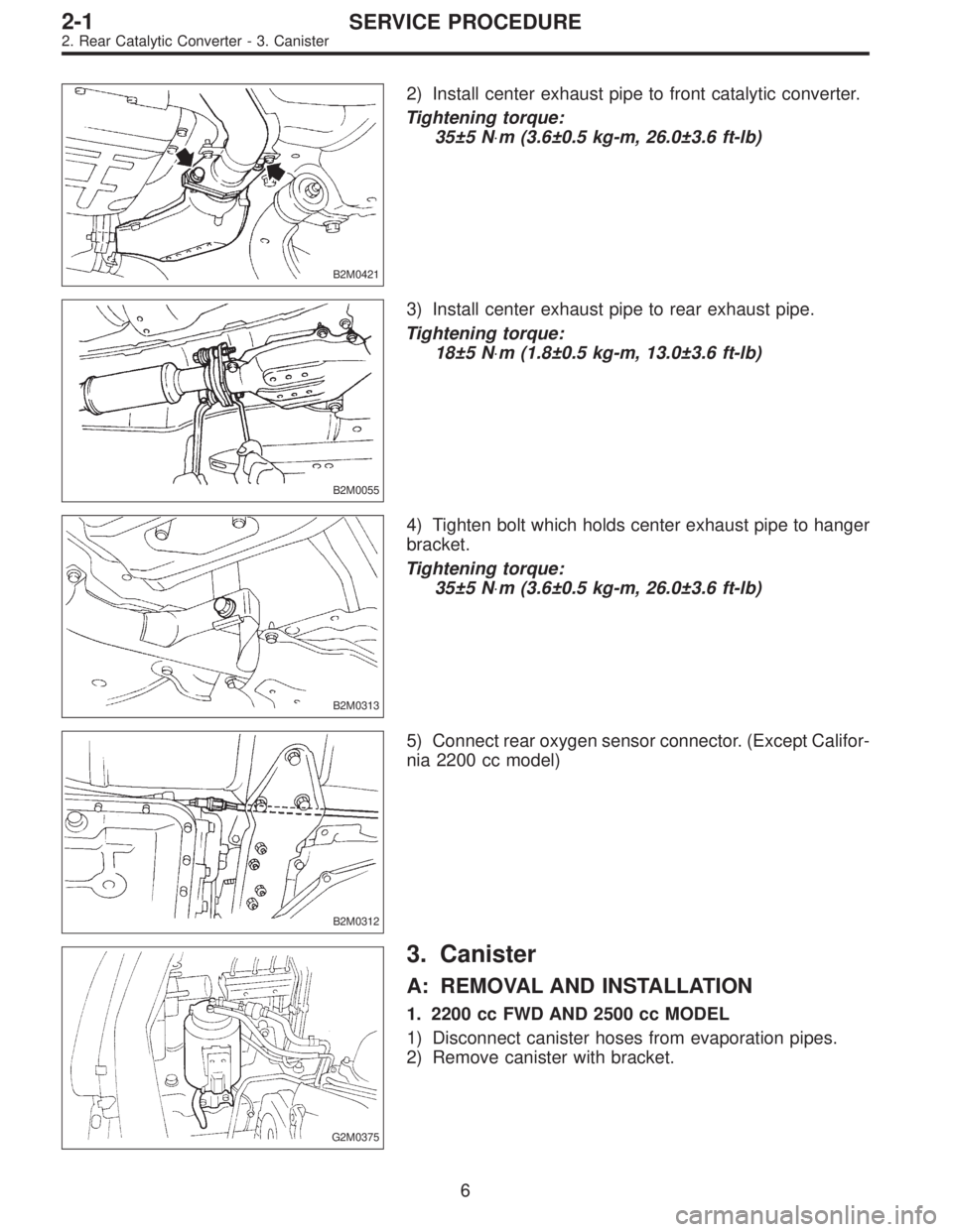
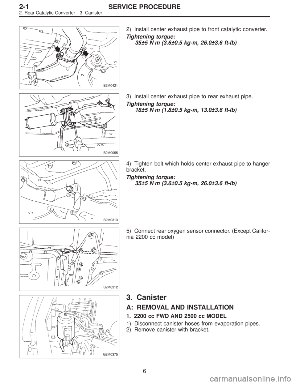
2) Install center exhaust pipe to front catalytic converter.
Tightening torque:
35±5 N⋅m (3.6±0.5 kg-m, 26.0±3.6 ft-lb)
B2M0055
3) Install center exhaust pipe to rear exhaust pipe.
Tightening torque:
18±5 N⋅m (1.8±0.5 kg-m, 13.0±3.6 ft-lb)
B2M0313
4) Tighten bolt which holds center exhaust pipe to hanger
bracket.
Tightening torque:
35±5 N⋅m (3.6±0.5 kg-m, 26.0±3.6 ft-lb)
B2M0312
5) Connect rear oxygen sensor connector. (Except Califor-
nia 2200 cc model)
G2M0375
3. Canister
A: REMOVAL AND INSTALLATION
1. 2200 cc FWD AND 2500 cc MODEL
1) Disconnect canister hoses from evaporation pipes.
2) Remove canister with bracket.
6
2-1SERVICE PROCEDURE
2. Rear Catalytic Converter - 3. Canister
Page 284 of 2890
B2M0421
2) Install center exhaust pipe to front catalytic converter.
Tightening torque:
35±5 N⋅m (3.6±0.5 kg-m, 26.0±3.6 ft-lb)
B2M0055
3) Install center exhaust pipe to rear exhaust pipe.
Tightening torque:
18±5 N⋅m (1.8±0.5 kg-m, 13.0±3.6 ft-lb)
B2M0313
4) Tighten bolt which holds center exhaust pipe to hanger
bracket.
Tightening torque:
35±5 N⋅m (3.6±0.5 kg-m, 26.0±3.6 ft-lb)
B2M0312
5) Connect rear oxygen sensor connector. (Except Califor-
nia 2200 cc model)
G2M0375
3. Canister
A: REMOVAL AND INSTALLATION
1. 2200 cc FWD AND 2500 cc MODEL
1) Disconnect canister hoses from evaporation pipes.
2) Remove canister with bracket.
6
2-1SERVICE PROCEDURE
2. Rear Catalytic Converter - 3. Canister
Page 285 of 2890
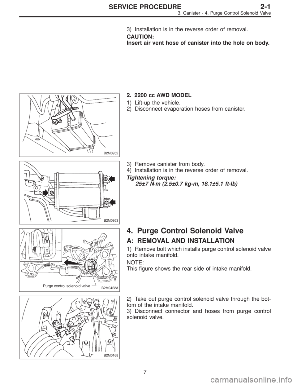
3) Installation is in the reverse order of removal.
CAUTION:
Insert air vent hose of canister into the hole on body.
B2M0952
2. 2200 cc AWD MODEL
1) Lift-up the vehicle.
2) Disconnect evaporation hoses from canister.
B2M0953
3) Remove canister from body.
4) Installation is in the reverse order of removal.
Tightening torque:
25±7 N⋅m (2.5±0.7 kg-m, 18.1±5.1 ft-lb)
B2M0422A
4. Purge Control Solenoid Valve
A: REMOVAL AND INSTALLATION
1) Remove bolt which installs purge control solenoid valve
onto intake manifold.
NOTE:
This figure shows the rear side of intake manifold.
B2M0168
2) Take out purge control solenoid valve through the bot-
tom of the intake manifold.
3) Disconnect connector and hoses from purge control
solenoid valve.
7
2-1SERVICE PROCEDURE
3. Canister - 4. Purge Control Solenoid Valve
Page 286 of 2890
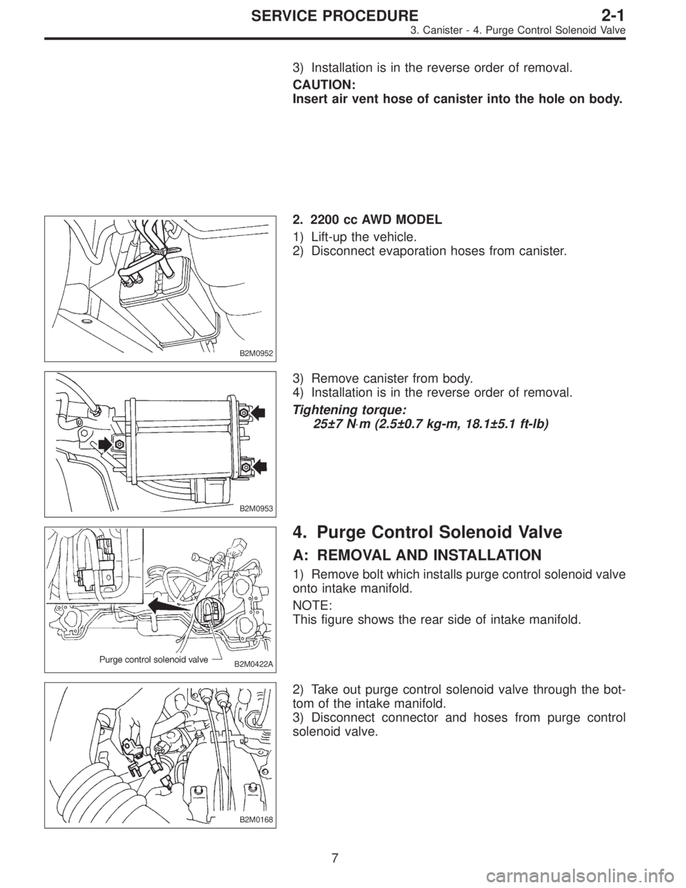
3) Installation is in the reverse order of removal.
CAUTION:
Insert air vent hose of canister into the hole on body.
B2M0952
2. 2200 cc AWD MODEL
1) Lift-up the vehicle.
2) Disconnect evaporation hoses from canister.
B2M0953
3) Remove canister from body.
4) Installation is in the reverse order of removal.
Tightening torque:
25±7 N⋅m (2.5±0.7 kg-m, 18.1±5.1 ft-lb)
B2M0422A
4. Purge Control Solenoid Valve
A: REMOVAL AND INSTALLATION
1) Remove bolt which installs purge control solenoid valve
onto intake manifold.
NOTE:
This figure shows the rear side of intake manifold.
B2M0168
2) Take out purge control solenoid valve through the bot-
tom of the intake manifold.
3) Disconnect connector and hoses from purge control
solenoid valve.
7
2-1SERVICE PROCEDURE
3. Canister - 4. Purge Control Solenoid Valve
Page 287 of 2890

4) Installation is in the reverse order of removal.
Tightening torque:
16±1.5 N⋅m (1.6±0.15 kg-m, 11.6±1.1 ft-lb)
B2M0423
5. EGR Valve
A: REMOVAL AND INSTALLATION
1) Disconnect vacuum hose from EGR valve.
2) Remove bolts which install EGR valve onto intake mani-
fold.
3) Installation is in the reverse order of removal.
CAUTION:
Replace gasket with a new one.
Tightening torque:
17.1 — 20.1 N⋅m (1.74 — 2.05 kg-m, 12.6 — 14.8
ft-lb)
B2M0424
6. Back-Pressure Transducer (BPT)
A: REMOVAL AND INSTALLATION
1) Disconnect vacuum hoses from BPT.
2) Remove BPT from bracket.
3) Installation is in the reverse order of removal.
8
2-1SERVICE PROCEDURE
4. Purge Control Solenoid Valve - 6. Back-Pressure Transducer (BPT)