check SUBARU LEGACY 1996 Service Repair Manual
[x] Cancel search | Manufacturer: SUBARU, Model Year: 1996, Model line: LEGACY, Model: SUBARU LEGACY 1996Pages: 2890, PDF Size: 61.9 MB
Page 3 of 2890
![SUBARU LEGACY 1996 Service Repair Manual 1-3
[0301]
GENERAL
INFORMATION
3
.
Vehicle
Identification
Numbers
(V
.I
.N)
3
.
Vehicle
Identification
Numbers
(V
.I
.N)
1
.
APPLICABLE
V
.I
.N
.
IN
THIS
MANUAL
Station
2200
cc
AWD
~
4AT
T
4
TS
3](/img/17/57433/w960_57433-2.png "SUBARU LEGACY 1996 Service Repair Manual 1-3
[0301]
GENERAL
INFORMATION
3
.
Vehicle
Identification
Numbers
(V
.I
.N)
3
.
Vehicle
Identification
Numbers
(V
.I
.N)
1
.
APPLICABLE
V
.I
.N
.
IN
THIS
MANUAL
Station
2200
cc
AWD
~
4AT
T
4
TS
3")
1-3
[0301]
GENERAL
INFORMATION
3
.
Vehicle
Identification
Numbers
(V
.I
.N)
3
.
Vehicle
Identification
Numbers
(V
.I
.N)
1
.
APPLICABLE
V
.I
.N
.
IN
THIS
MANUAL
Station
2200
cc
AWD
~
4AT
T
4
TS
3
1
B
I
KT
I
9
I
5X
I
T
I
8
I
T
2
00
1
and
after
Wagon
engine
POST
2
.
THE
MEANINGOF
V
.I
.N
.
Marker
identifier
l
Stop-
mark
4
S
3
Sequential
number
302001
and
after
:
Station
Wagon
Plant
of
manufacture
and
transmission
type
Plant
of
manufacture
Transmissiontype
SIA
POST
8
(Full-time
AWD
4AT)
Model
year
T
1996
Check
digit
Weight
class
and
restraint
type
Passenger
car
5
:
Withoutpassive
restraint,
with
Dual
SRS
airbag
Model
9
:
POST
Engine
type
4
:
2
.2
liter
engine
Body
type
K
:
Station
Wagon
Line
B
:
SUBARU
B
line
Plant
of
manufacture
Plant
of
manufacture
Type
of
vehicle
SIA
I
4S3
~
Passenger
car
I
Vehicle
attributes
Check
digit
Vehicle
identification
BK
495
X
T
83
0200
1
[
TT
I
T
T
ITT
Z
Stop
mark
2
Page 16 of 2890
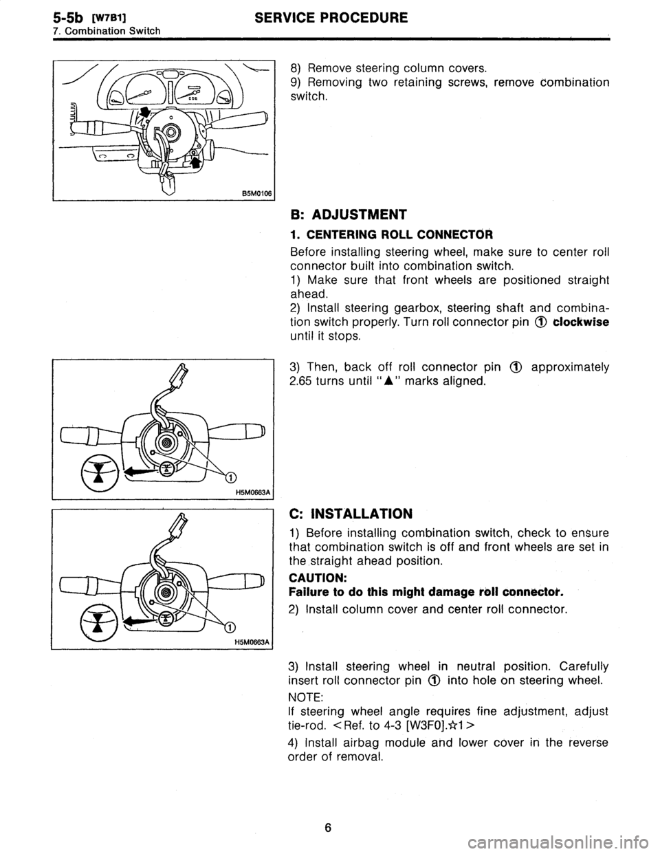
5-5b
[W7B1)
SERVICE
PROCEDURE
7
.
Combination
Switch
8)
Remove
steering
column
cowers
.
9)
Removing
two
retaining
screws,
remove
combination
switch
.
B
:
ADJUSTMENT
1
.
CENTERING
ROLL
CONNECTOR
Before
installing
steering
wheel,
make
sure
to
center
roil
connector
built
into
combination
switch
.
1)
Make
sure
that
front
wheels
are
positioned
straight
ahead
.
2)
Install
steering
gearbox,
steering
shaft
and
combina-
tion
switchproperly
.
Turn
roll
connector
pin
(J)
clockwise
until
it
stops
.
3)
Then,
back
off
roll
connector
pin
1~
approximately
2
.65
turns
until
"A"
marks
aligned
.
C
:
INSTALLATION
1)
Before
installing
combination
switch,
check
to
ensure
that
combination
switch
is
off
and
font
wheels
are
set
in
the
.straight
ahead
position
.
CAUTION
:
Failure
to
do
this
might
damage
roll
connoctok
.
2)
Install
column
cover
and
center
roll
connector
.
3)
Install
steering
wheel
in
neutral
position
.
Carefully
insert
roll
connector
pin
1(~
into
hole
on
steering
wheel
.
NOTE
:
If
steering
wheel
angle
requires
fine
adjustment,
adjust
tie-rod
.
<
Ref
.
to
4-3
[W3FOj
.*1
>
4)
Install
airbag
module
and
lower
cover
in
the
reverse
order
of
removal
.
6
Page 18 of 2890
![SUBARU LEGACY 1996 Service Repair Manual
ON-BOARD
DIAGNOSTICS
II
SYSTEM
[Tiq2]
2-
1
.
General
1~
Engine
control
module
(ECM)
~
Radiator
fan
~2
Ignition
coil~s
Radiator
fan
relay
~3
Ignitqr
~s
Pressure
sources
switching
solenoid
valve
~](/img/17/57433/w960_57433-17.png "SUBARU LEGACY 1996 Service Repair Manual
ON-BOARD
DIAGNOSTICS
II
SYSTEM
[Tiq2]
2-
1
.
General
1~
Engine
control
module
(ECM)
~
Radiator
fan
~2
Ignition
coil~s
Radiator
fan
relay
~3
Ignitqr
~s
Pressure
sources
switching
solenoid
valve
~")
ON-BOARD
DIAGNOSTICS
II
SYSTEM
[Tiq2]
2-
1
.
General
1~
Engine
control
module
(ECM)
~
Radiator
fan
~2
Ignition
coil~s
Radiator
fan
relay
~3
Ignitqr
~s
Pressure
sources
switching
solenoid
valve
~4
Crankshaft
position
sensor
~
Knock
sensor
~5
Camshaft
position
sensor
~
Back-pressure
transducer
Throttle
position
sensor
~s
Front
oxygen
sensor
~7
duel
injectors
~o
Rear
oxygen
sensor
(Except
California
model)
~8
Pressure
regulator
~
Pressure
sensor
Engine
coolant
temperature
sensor
~z
A/C
compressor
~o
Mass
air
flow
sensor
~
Inhibitor
switch
Idle
air
control
solenoid
valve
~
CHECK
ENGINE
malfunction
indicator
lamp
(MIL)
~z
Purge
control
solenoid
valve
~
Tachometer
0
Fuel
pump
~s
A/C
relay
0
PCV
valve
~
A/C
control
module
~s
Air
cleaner
~eIgnition
switch
Canister
~
Transmission
control
module
(TCM)
~
Main
relay
~o
Vehicle
speed
sensor
2
~a
Fuel
pump
relay
~
Data
link
connector
(For
Subaru
select
monitor)
~s
Fuel
filter
@
Data
link
connector
(For
Subaru
select
monitor
and
~o
Front
catalytic
converter
OBD-II
general
scan
tool)
Rear
catalytic
converter
@
Two
way
valve
~2
MGR
valve
~a
Rear
oxygen
sensor
(California
model
only)
EGR
control
solenoid
valve
~
Filter
3
Page 34 of 2890
![SUBARU LEGACY 1996 Service Repair Manual
ON-BOARD
DIAGNOSTICS
II
SYSTEM
[T3C6]
2-7
3
.
Diagnosis
System
Function
mode
Contents
Abbreviation
Unit
of
measure
FB1
Diagnostic
trouble
code
(DTC)
OBD
-
Load
data
(Freeze
frame
data)
LOAD-F
Eng](/img/17/57433/w960_57433-33.png "SUBARU LEGACY 1996 Service Repair Manual
ON-BOARD
DIAGNOSTICS
II
SYSTEM
[T3C6]
2-7
3
.
Diagnosis
System
Function
mode
Contents
Abbreviation
Unit
of
measure
FB1
Diagnostic
trouble
code
(DTC)
OBD
-
Load
data
(Freeze
frame
data)
LOAD-F
Eng")
ON-BOARD
DIAGNOSTICS
II
SYSTEM
[T3C6]
2-7
3
.
Diagnosis
System
Function
mode
Contents
Abbreviation
Unit
of
measure
FB1
Diagnostic
trouble
code
(DTC)
OBD
-
Load
data
(Freeze
frame
data)
LOAD-F
Engine
coolant
temperature
signal
(Freeze
frame
data)
TW-F
°C
Throttleposition
signal
(Freeze
frame
data)
ALPH-F
FB2
Long
term
fuel
trim
(Freeze
frame
data)
KBLR-F
Intake
manifoldabsolute
pressure
signal
(Freeze
frame
data)
MANI-F
kPa
Engine
speed
signal
(Freeze
frame
data)
EREV-F
rpm
Vehicle
speed
signal
(Freeze
frame
data)
VSP-F
km/h
Mass
air
flow
signal
(Freeze
frame
data)
QA-F
(P0100)
V
Pressure
signal
(Freeze
frame
data)
PS-F
(P0105)
V
Pressure
signal
(Freeze
frame
data)
PR-F
(P0106)
V
Engine
coolant
temperature
signal
(Freeze
frame
data)
TW-F
(P0115)
V
Throttleposition
signal
(Freeze
frame
data)
THV-F
(P0120)
V
17133
EGR
control
solenoid
valve
signal
(Freeze
frame
data)
EGR
(P0403)
-*1
Purge
control
solenoid
valve
signal
(Freeze
frame
data)
CPC
(P0443)
_*1
Start
switch
signal
(Freeze
frame
data)
STSW
(P1100)
_*1
Pressure
sources
switching
solenoid
valve
signal
(Freeze
frame
data)
gR1
(P1102)
_*1
Radiator
fanrelay
1
signal
(Freeze
frame
data)
FAN1
(P1500)
_*1
FCO
Clear
memory
-
-
FD01
Compulsory
fuel
pump
relay
operation
check
FUEL
PUMP
-
FD02
Compulsory
purge
control
solenoid
valveoperation
check
CPCSOL
-
FD03
Compulsory
radiator
fan
relay
operation
check
RAD
FAN
-
FD04
Compulsory
A/C
relay
operation
check
A/C
RELAY
-
FD05
Compulsory
EGR
control
solenoid
valve
operation
check
EGR
SOL
-
FD10
Compulsory
pressure
sources
switching
solenoid
valve
operation
check
BR
SOS
-
NOTE
:
1)
Subaru
select
monitor
is
also
available
for
monitoring
information
other
than
that
used
for
check
and
repair
of
the
vehicle
.
2)
F42
(Maximumandminimum
EGR
system
pressure
value)
will
not
read
accurately
until
the
EGR
flow
diagno-
sis
terminates
.
EGR
flow
diagnosis
terminates
when
LED
No
.
2
illuminates
at
function
mode
FA4
.
3)*1
:
"Hi"or
"Low"
is
shown
instead
of
measured
value
.
4)
Because
valve
is
not
installed,
FD06,
FD07,FD08,
FD09
and
FD11
will
be
displayed
but
non-functional
.
19
Page 35 of 2890
![SUBARU LEGACY 1996 Service Repair Manual
2-7
[T3C7]
ON-BOARD
DIAGNOSTICS
II
SYSTEM
3
.
Diagnosis
System
82M0476
7
.
FUNCTION
MODE
:
F00
-
ROM
ID
NUMBER
(YEAR)
-
CONDITION
:
Ignition
switch
"ON"
SPECIFIED
DATA
:
Presentation
display](/img/17/57433/w960_57433-34.png "SUBARU LEGACY 1996 Service Repair Manual
2-7
[T3C7]
ON-BOARD
DIAGNOSTICS
II
SYSTEM
3
.
Diagnosis
System
82M0476
7
.
FUNCTION
MODE
:
F00
-
ROM
ID
NUMBER
(YEAR)
-
CONDITION
:
Ignition
switch
\"ON\"
SPECIFIED
DATA
:
Presentation
display")
2-7
[T3C7]
ON-BOARD
DIAGNOSTICS
II
SYSTEM
3
.
Diagnosis
System
82M0476
7
.
FUNCTION
MODE
:
F00
-
ROM
ID
NUMBER
(YEAR)
-
CONDITION
:
Ignition
switch
"ON"
SPECIFIED
DATA
:
Presentation
display
Probable
cause
(Item
outside"specifieddata")
1
.
Error
1
2
.
Error2
vB
(F01)
12
.4
V
B2M0270
Probable
cause
(Item
outside
"specified
data")
1
.
Battery
1
2
.
Charging
system
1
3
.
Power
supply
line
Check
for
loose
or
disconnected
connector,
and
discontinued
circuit,
etc
.
Check
for
poor
contact
of
cartridge,
or
different
type
cartridge
.
8
.
FUNCTION
MODE
:
F01
-
BATTERY
VOLTAGE
(VB)
-
CONDITION
:
(1)
Ignition
switch
"ON"
(2)
Idling
after
warm-up
SPECIFIED
DATA
:
(1)
111
V
(2)
13
f
1
V
Check
battery
voltage
and
electrolyte's
specific
gravity
.
"
Check
regulating
voltage
.
(On
no-load)
Check
alternator
.
o
Check
main
relay
.
<
Ref
.
to
[T9C0]
.*4>
*
Check
harness
connector
of
ECM
power
supply
line
.
to
[T9C0]
.*4>
20
Page 46 of 2890
![SUBARU LEGACY 1996 Service Repair Manual
ON-BOARD
DIAGNOSTICS
11
SYSTEM
[T3C45]
2-7
3
.
Diagnosis
System
43
.
FB
MODE
FOR
ENGINE
Function
mode
AbbreviationContentsContents
of
display
Page
On-board
diagnostics
Current
trouble
code
indica](/img/17/57433/w960_57433-45.png "SUBARU LEGACY 1996 Service Repair Manual
ON-BOARD
DIAGNOSTICS
11
SYSTEM
[T3C45]
2-7
3
.
Diagnosis
System
43
.
FB
MODE
FOR
ENGINE
Function
mode
AbbreviationContentsContents
of
display
Page
On-board
diagnostics
Current
trouble
code
indica")
ON-BOARD
DIAGNOSTICS
11
SYSTEM
[T3C45]
2-7
3
.
Diagnosis
System
43
.
FB
MODE
FOR
ENGINE
Function
mode
AbbreviationContentsContents
of
display
Page
On-board
diagnostics
Current
trouble
code
indicated
by
FBOINSPECT
(Inspection)
on-board
diagnostics
after
clear
mem-
[T3E1]*2
ory
.
FB1
OBD
On-board
diagnostics
Current
trouble
code
indicated
by
14
(Read
data)
on-board
diagnostics
.
LOAD-F
Load
data
TW-F
Engine
coolant
temper-
aturesignal
ALPH-F
Throttleposition
signal
*
Freeze
frame
data
FB2
KBLR-F
Long
term
fuel
trim
*
Data
stored
at
the
time
of
trouble
15
Intake
manifold
abso-
occurrence,
is
shownon
display
.
MANI-F
lute
pressure
signal
EREV-F
Engine
speed
signal
VSP-F
Vehicle
speed
signal
QA-F
(P0100)
Mass
air
flow
signal
PS-F
(P0105)
Pressure
signal
PR-F
(P0106)
Pressure
signal
TW-r
(P0115)
Engine
coolant
temper-
ature
signal
THV-F
(P0120)
Throttleposition
signal
EGR
(P0403)
EGR
control
solenoid
,
Freeze
frame
data
FB3
valve
signal
9
Data
stored
at
the
time
of
trouble16
CPC
(P0443)
Purge
control
solenoid
occurrence,
is
shown
on
display
.
valve
signal
STSW
(P1100)
Start
switch
signal
Pressure
sources
BR1
(P1102)
switching
solenoid
valve
signal
FAN1
(P1500)
Radiator
fan
relay
1
signal
44
.
FC
MODE
FOR
ENGINE
Function
mode
Abbreviation
ContentsContents
of
display
Page
FCO
MEMORY
CLR
Back-up
memory
clear
Function
of
clearing
trouble
code
[T3D1]*2
stored
in
memory
.
45
.
FD
MODE
FOR
ENGINE
Function
mode
Abbreviation
ContentsContents
of
display
Page
FD01
FUEL
PUMP
FD02
CPCSOL
Function
of
checking
operation
offuel
FD03
RAD
FAN
Compulsory
valve
pump
relay,
purge
control
solenoid
A/C
ll
di
tf
l
39
FD04
A/C
RELAY
operation
check
an
re
revave,
ra
a
or
ay,
ay,
EGR
control
solenoid
valve
and
pres-
FD05
EGR
SOL
sure
sources
switching
valve
.
FD10
BR
SOL
NOTE
:
Because
valve
is
not
installed,
FD06,
FD07,
FD08,
FD09
and
FD11
will
be
displayed
but
non-functional
.
31
Page 49 of 2890
![SUBARU LEGACY 1996 Service Repair Manual
2-7
[T3C48]
ON-BOARD
DIAGNOSTICS
II
SYSTEM
3
.
Diagnosis
System
E-4AT
(F00)
4WD
1993
G3M0723
Probable
cause
(if
outside"specifieddata")
48
.
FUNCTION
MODE
:
F00
-
MODE
DISPLAY
-
SPECIFIED
DATA](/img/17/57433/w960_57433-48.png "SUBARU LEGACY 1996 Service Repair Manual
2-7
[T3C48]
ON-BOARD
DIAGNOSTICS
II
SYSTEM
3
.
Diagnosis
System
E-4AT
(F00)
4WD
1993
G3M0723
Probable
cause
(if
outside\"specifieddata\")
48
.
FUNCTION
MODE
:
F00
-
MODE
DISPLAY
-
SPECIFIED
DATA")
2-7
[T3C48]
ON-BOARD
DIAGNOSTICS
II
SYSTEM
3
.
Diagnosis
System
E-4AT
(F00)
4WD
1993
G3M0723
Probable
cause
(if
outside"specifieddata")
48
.
FUNCTION
MODE
:
F00
-
MODE
DISPLAY
-
SPECIFIED
DATA
:
Data
at
the
left
shouldbe
indicated
.
1
.
Communication
failure
(1)
Check
loose
or
poor
connectors,
or
(No
communication
method
can
be
confirmed
with
power
ON
.)
(2)
shortcircuit
.
Check
type
of
cartridge
.
2
.
Vehicle
types
cannot
be
identified
(due
to
communication
failure)
.
VB
(F01)
12
.7
V
OBD0673
1
.
Battery
1
2
.
Charging
system
Check
improper
cartridge
.
Replace
with
proper
one
.
49
.
FUNCTION
MODE
:
F01
-
BATTERY
VOLTAGE
(VB)
-
CONDITION
:
(1)
Ignition
switch
ON
(2)
Engine
idling
after
warm-up
SPECIFIED
DATA
:
(1)
12±1
V
(2)
13
±
1
V
Check
battery
voltage
and
specific
gravity
of
electrolyte
.
(1)
I
Measure
regulatingvoltage
under
no
loads
.
(2)
Check
generator
(as
asingle
unit)
.
34
Page 53 of 2890
![SUBARU LEGACY 1996 Service Repair Manual 2-7
[T3E2]
ON-BOARD
DIAGNOSTICS
II
SYSTEM
3
.
Diagnosis
System
ST2
D
00000
O
00000
00000
"
u
~O
O
r0====z3
STI
OBDO057A
E
:
INSPECTION
MODE
2
.
SUBARU
SELECT
MONITOR
After
performing
diagnos](/img/17/57433/w960_57433-52.png "SUBARU LEGACY 1996 Service Repair Manual 2-7
[T3E2]
ON-BOARD
DIAGNOSTICS
II
SYSTEM
3
.
Diagnosis
System
ST2
D
00000
O
00000
00000
\"
u
~O
O
r0====z3
STI
OBDO057A
E
:
INSPECTION
MODE
2
.
SUBARU
SELECT
MONITOR
After
performing
diagnos")
2-7
[T3E2]
ON-BOARD
DIAGNOSTICS
II
SYSTEM
3
.
Diagnosis
System
ST2
D
00000
O
00000
00000
"
u
~O
O
r0====z3
STI
OBDO057A
E
:
INSPECTION
MODE
2
.
SUBARU
SELECT
MONITOR
After
performing
diagnostics
and
clearing
the
memory,
check
for
any
remaining
unresolved
trouble
data
.
1)
Prepare
Subaru
select
monitor
and
cartridge
.
ST1
498307500
SELECT
MONITOR
KIT
ST2
498345700
CARTRIDGE
2)
Turn
ignition
switch
andSubaru
select
monitor
switch
to
OFF
.
3)
Insert
cartridge
into
Subaru
select
monitor
.
1
0
C,
00~~
F
0000
E
0000
0
000
G3MO1501
4)
Connect
test
mode
connector
at
the
lower
portion
of
instrument
panel
(onthe
driver's
side),
to
the
side
of
the
center
console
box
.
Test
mode
connector
B2M0432B
I
\
Subaru
select
monitor
1
o
cocoaoaooo
cocoaoooou
a---
7
82M0829A
5)
Connect
Subaru
select
monitor
to
data
link
connector
.
*
Using
data
link
connector
for
Subaru
select
monitor
only
:
Connect
Subaru
select
monitor
to
its
data
link
connector
located
in
the
lower
portion
of
the
instrument
panel
(on
the
driver's
side),
to
the
side
of
thecenter
console
box
.
38
Page 54 of 2890
![SUBARU LEGACY 1996 Service Repair Manual
ON-BOARD
DIAGNOSTICS
II
SYSTEM
[raFi]
2-7
3
.
Diagnosis
System
I
ST
I
1-1
ooaao0000000000oaooo
OBD0669A
I
ST2
00000
I
0
0
(03C03
0
~
00000
;
i~~
C01-
ST1
OBDD057A
9
Using
data
link
connector](/img/17/57433/w960_57433-53.png "SUBARU LEGACY 1996 Service Repair Manual
ON-BOARD
DIAGNOSTICS
II
SYSTEM
[raFi]
2-7
3
.
Diagnosis
System
I
ST
I
1-1
ooaao0000000000oaooo
OBD0669A
I
ST2
00000
I
0
0
(03C03
0
~
00000
;
i~~
C01-
ST1
OBDD057A
9
Using
data
link
connector")
ON-BOARD
DIAGNOSTICS
II
SYSTEM
[raFi]
2-7
3
.
Diagnosis
System
I
ST
I
1-1
ooaao0000000000oaooo
OBD0669A
I
ST2
00000
I
0
0
(03C03
0
~
00000
;
i~~
C01-
ST1
OBDD057A
9
Using
data
link
connector
for
Subaru
select
monitor
and
OBD-II
general
scan
tool
:
(1)
Connect
ST
to
Subaru
select
monitorcable
.
ST
498357200
ADAPTER
CABLE
(2)
Open
the
cover
and
connect
Subaru
select
moni-
torto
data
link
connector
located
in
thelower
portion
of
the
instrument
panel(on
the
driver'sside),to
the
lower
cover
.
CAUTION
:
Do
not
connect
scan
tools
except
for
Subaru
select
mon-
itor
and
OBD-II
general
scan
tool
.
6)
Turn
ignition
switch
to
ON
(engine
OFF)
and
Subaru
select
monitor
switch
to
ON
.
7)
Start
the
engine
.
NOTE
:
Ensure
the
selector
lever
is
placed
in
the
"P"
position
before
starting
.
8)
Using
the
selector
lever
or
shift
lever,
turn
the
"P"
posi-
tion
switch
and
the
"N"
position
switch
to
ON
.
9)
Depress
the
brake
pedal
to
turn
the
brake
switch
ON
.
10)
Keep
engine
speed
in
the
2,500-3,000
rpm
range
for
40
seconds
.
NOTE
:
On
models
without
tachometer,
usethe
Subaru
select
monitor
or
tachometer
(Secondary
pickup
type)
.
11)
Place
the
selector
lever
or
shift
lever
in
the
"D"
posi-
tion
and
drive
the
vehicle
at
5
to
10
km/h
(3to
6
MPH)
.
NOTE
:
On
AWD
vehicles,
release
the
parking
brake
.
F
:
COMPULSORY
VALVE
OPERATION
CHECK
MODE
1
.
SUBARU
SELECT
MONITOR
1)
Prepare
Subaru
select
monitor
and
cartridge
.
ST1
498307500
SELECT
MONITOR
KIT
ST2
498345700
CARTRIDGE
39
Page 57 of 2890
![SUBARU LEGACY 1996 Service Repair Manual 2-7
[T3G1]
ON-BOARD
DIAGNOSTICS
II
SYSTEM
3
.
Diagnosis
System
EGR
SOL
(FDOS)
OX
IN
1
[0],
[ENT]
BMW
I
EGR
SOL
(FDOS)
*CHK*
O
:Y
1
:N
82M0652
EGR
SOL
(FDOS)
OX
1N
1
[1],
[ENT]
82M0653
I
E](/img/17/57433/w960_57433-56.png "SUBARU LEGACY 1996 Service Repair Manual 2-7
[T3G1]
ON-BOARD
DIAGNOSTICS
II
SYSTEM
3
.
Diagnosis
System
EGR
SOL
(FDOS)
OX
IN
1
[0],
[ENT]
BMW
I
EGR
SOL
(FDOS)
*CHK*
O
:Y
1
:N
82M0652
EGR
SOL
(FDOS)
OX
1N
1
[1],
[ENT]
82M0653
I
E")
2-7
[T3G1]
ON-BOARD
DIAGNOSTICS
II
SYSTEM
3
.
Diagnosis
System
EGR
SOL
(FDOS)
OX
IN
1
[0],
[ENT]
BMW
I
EGR
SOL
(FDOS)
*CHK*
O
:Y
1
:N
82M0652
EGR
SOL
(FDOS)
OX
1N
1
[1],
[ENT]
82M0653
I
EGR
SOL(FDOS)
END
OF
CHECK
1996
(F00)
-2
.2
SOHC
BMW
10)
Press
thefunction
key
.
(1)
When
executing,
press
the
function
key
[0]
.
NOTE
.
When
in
compulsory
valve
operation
check
mode
the
monitor
indicates
the
execution
of
valve
check
on
display
.
(2)
When
not
executing
or
stopping
the
compulsory
valve
checkmode,
press
thefunction
key
[1]
.
11)
When
compulsory
valve
operation
check
mode
is
exited
or
check
completed,
the
monitor
indicates
the
com-
pletion
of
compulsory
valve
operation
check
on
the
display,
and
automatically
returns
to
the
initial
mode
(FUNCTION
MODE
:
F00)
.
G
:
FINISHING
DIAGNOSIS
OPERATION
1
.
SUBARU
SELECT
MONITOR
1)
Disconnect
test
mode
connector
at
the
lower
portion
of
instrument
panel
(onthe
driver's
side),
to
the
side
of
the
center
console
box
.
2)
Turn
Subaru
select
monitor
switch
and
ignition
switch
to
OFF
.
3)
Disconnect
Subaru
select
monitorfrom
its
data
link
connector
.
42