wiring SUBARU LEGACY 1997 Service Repair Manual
[x] Cancel search | Manufacturer: SUBARU, Model Year: 1997, Model line: LEGACY, Model: SUBARU LEGACY 1997Pages: 3342, PDF Size: 62.95 MB
Page 3 of 3342

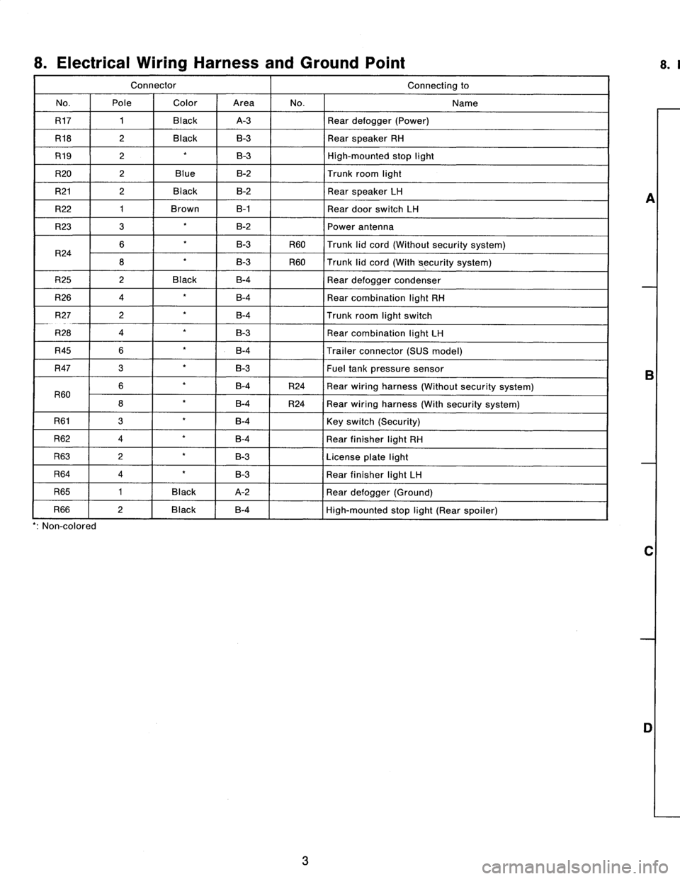
8
.
Electrical
Wiring
Harness
and
Ground
Point
Connector
Connecting
to
No
.
Pole
Color
Area
No
.
Name
R17
1
Black
A-3
Rear
defogger
(Power)
R18
2
Black
B-3
Rear
speaker
RH
R19
2B-3
High-mounted
stop
light
R20
2
Blue
B-2
Trunk
room
light
R21
2
Black
B-2
Rear
speaker
LH
R22
1
Brown
B-1
Rear
door
switch
LH
R23
3
B-2
Power
antenna
R24
6B-3
R60
Trunk
lid
cord(Without
security
system)
8
B-3
R60
Trunk
lid
cord
(With
security
system)
R25
2
Black
B-4
Rear
defogger
condenser
R26
4
B-4
Rear
combination
light
RH
R27
2
B-4
Trunk
room
light
switch
R28
4
B-3
Rear
combination
light
LH
R45
6
B-4
Trailer
connector
(SUS
model)
R47
3B-3Fueltank
pressure
sensor
R60
6B-4
R24
Rear
wiring
harness
(Without
security
system)
8B-4
R24
Rear
wiring
harness
(With
security
system)
R61
3B-4
Key
switch
(Security)
R62
4B-4
Rear
finisher
light
RH
R63
2B-3
License
plate
light
R64
4B-3
Rear
finisher
light
LH
R65
1
Black
A-2
Rear
defogger(Ground)
R66
2
Black
B-4
E
High-mounted
stop
light
(Rear
spoiler)
'
:
Non-colored
3
A
B
C
D
8
.
REAR
END
WIRING
HARNESS
AND
GROUND
POINT
OF
SEDAN
1
1
2
1
3
R65
1
R17
,
R19
4
\
R66
GD
A
~
~
R45
i
O
~~`
R18
''r
~
R25
R21
~
~O
\
R22
O
R20
R24
R47
~---
R23R2g
'
:
R60
R62
o
GB-9
0
~~,
.~I
~~I)~1
B6M0104B
2
R63R26
R64R27
R61~
~
GB-9
3
[D808]
B6M0823A
4
A
B
C
D
Page 16 of 3342

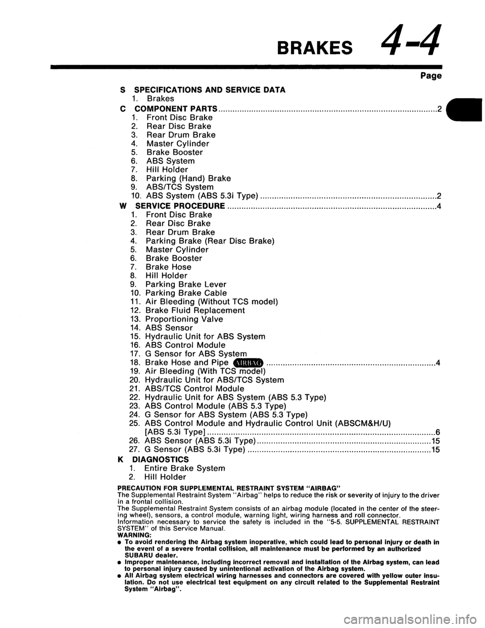
BRAKES
44
Page
S
SPECIFICATIONS
AND
SERVICE
DATA
1
.
Brakes
C
COMPONENT
PARTS
...........
.
.
.
.....................
.
.
......
..
.
.
.
..........................
1
.
FrontDisc
Brake
2
.
Rear
Disc
Brake
3
.
Rear
Drum
Brake
4
.
Master
Cylinder
5
.
Brake
Booster
6
.
ABS
System
7
.
Hill
Holder
8
.
Parking
(Hand)
Brake
9
.
ABS/TCS
System
10
.
ABS
System(ABS
5
.3i
Type)
...
....
.
...
..........................
.
.
...
.
.............
W
SERVICE
PROCEDURE
...............
.
.
......
.
.
...
.
....................
.
.
.
.
.
.
...
.
...
.
.......
1
.
Front
Disc
Brake
2
.
Rear
Disc
Brake
3
.
Rear
Drum
Brake
4
.
Parking
Brake
(Rear
Disc
Brake)
5
.
Master
Cylinder
6
.
Brake
Booster
7
.
Brake
Hose
8
.
Hill
Holder
9
.
Parking
Brake
Lever
10
.
Parking
Brake
Cable
11
.
Air
Bleeding
(Without
TCS
model)
12
.
Brake
Fluid
Replacement
13
.
Proportioning
Valve
14
.
ABS
Sensor
15
.
Hydraulic
Unit
for
ABS
System
16
.
ABS
Control
Module
17
.
G
Sensor
for
ABS
System
18
.
Brake
Hose
and
Pipe
am
.
.
.....
.
.................................
.
.
...
.
.....
..
19
.
Air
Bleeding
(With
TCS
model)
20
.
Hydraulic
Unit
for
ABS/TCS
System
21
.
ABS/TCS
Control
Module
22
.
Hydraulic
Unit
for
ABS
System
(ABS
5
.3
Type)
23
.
ABS
Control
Module
(ABS
5
.3
Type)
24
.
G
Sensor
for
ABS
System
(ABS
5
.3
Type)
25
.
ABS
Control
Module
and
Hydraulic
Control
Unit
(ABSCM&H/U)
[ABS
5
.3i
Type]
.
.
.
.
.
.
.
...
.
.
.
.
.
..
.
.
...................................
.
...
.
.
.........
..........
26
.
ABS
Sensor
(ABS
5
.3i
Type)
....
...........................................
.
.
....
.
...
.
27
G
Sensor
(ABS
5
3i
T
e)
2
....
.2
....
.4
........
.
.
..
.4
....
..
.15
....
..
.15
yp
....
.
.
......
...
.
...................................
.
.
.
.
.......
.
.
.....
K
DIAGNOSTICS
1
.
Entire
BrakeSystem
2
.
Hill
Holder
PRECAUTION
FORSUPPLEMENTAL
RESTRAINT
SYSTEM
"AIRBAG"
The
Supplemental
Restraint
System
"Airbag"
helps
to
reduce
the
risk
or
severity
of
injury
to
the
driver
in
a
frontal
collision
.
The
Supplemental
Restraint
System
consists
of
an
airbag
module
(located
in
the
center
of
the
steer-
ing
wheel),sensors,
a
control
module,warning
light,
wiring
harness
and
roll
connector
.
Information
necessary
to
servicethe
safety
is
included
in
the"5-5
.
SUPPLEMENTAL
RESTRAINT
SYSTEM"
ofthis
Service
Manual
.
WARNING
:
"
To
avoid
rendering
the
Airbag
system
inoperative,
which
could
lead
to
personal
injury
or
death
in
the
event
of
a
severe
frontal
collision,
all
maintenance
must
be
performed
byan
authorized
SUBARU
dealer
.
"
Improper
maintenance,
including
incorrect
removal
and
installation
of
the
Airbag
system,
can
lead
to
personal
injury
caused
by
unintentional
activation
of
the
Airbag
system
.
"
All
Airbag
system
electrical
wiring
harnesses
and
connectors
are
covered
with
yellow
outer
insu-
lation
.
Do
not
use
electrical
test
equipment
on
any
circuit
relatedtothe
Supplemental
Restraint
System
"Airbag"
.
Page 19 of 3342

4-4
twisoot
SERVICE
PROCEDURE
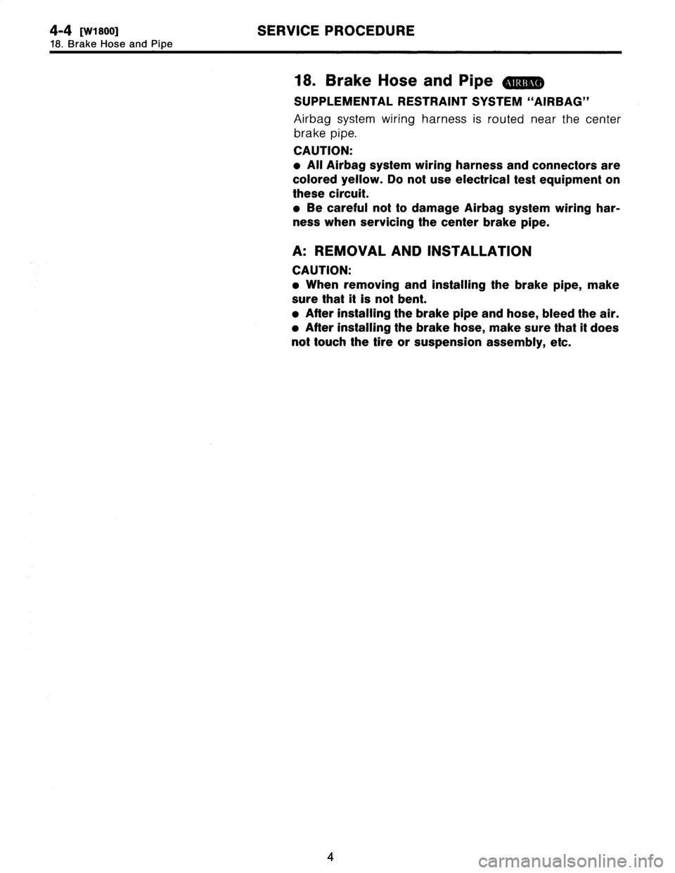
18
.
Brake
Hose
and
Pipe
18
.
Brake
Hoseand
Pipe
SUPPLEMENTAL
RESTRAINT
SYSTEM
"AIRBAG"
Airbagsystem
wiring
harness
is
routed
near
the
center
brake
pipe
.
CAUTION
:
All
Airbag
system
wiring
harness
and
connectors
are
colored
yellow
.
Do
not
use
electrical
test
equipment
on
these
circuit
.
o
Be
careful
not
to
damage
Airbag
system
wiring
har-
ness
when
servicing
thecenter
brake
pipe
.
A
:
REMOVAL
AND
INSTALLATION
CAUTION
:
When
removing
and
installing
the
brake
pipe,
make
sure
that
it
is
notbent
.
"
After
installing
the
brake
pipe
and
hose,bleed
the
air
.
"
After
installing
the
brake
hose,
make
sure
that
if
does
not
touch
the
tire
or
suspension
assembly,
etc
.
4
Page 31 of 3342
![SUBARU LEGACY 1997 Service Repair Manual
4-4d
[T1oo]
BRAKES
[ABS
5
.31
TYPE]
1
.
Supplemental
Restraint
System
"Airbag"
-
2
.
Pre-inspection
1
.
Supplemental
Restraint
System
"Airbag"
Airbagsystem
wiring
harness
is
routed
near
the
ABS
SUBARU LEGACY 1997 Service Repair Manual
4-4d
[T1oo]
BRAKES
[ABS
5
.31
TYPE]
1
.
Supplemental
Restraint
System
"Airbag"
-
2
.
Pre-inspection
1
.
Supplemental
Restraint
System
"Airbag"
Airbagsystem
wiring
harness
is
routed
near
the
ABS](/img/17/57434/w960_57434-30.png)
4-4d
[T1oo]
BRAKES
[ABS
5
.31
TYPE]
1
.
Supplemental
Restraint
System
"Airbag"
-
2
.
Pre-inspection
1
.
Supplemental
Restraint
System
"Airbag"
Airbagsystem
wiring
harness
is
routed
near
the
ABS
sensor,
ABS
control
module
and
hydraulic
control
unit
.
CAUTION
:
All
Airbag
system
wiring
harness
and
connectors
are
colored
yellow
.
Do
not
use
electrical
test
equipment
on
these
circuit
.
e
Be
careful
not
to
damage
Airbag
system
wiring
har-
ness
when
servicing
the
ABS
sensor,
ABS
control
mod-
ule
and
hydraulic
control
unit
.
2
.
Pre-inspection
Before
performing
diagnostics,
check
the
following
items
which
might
affect
ABS
problems
:
A
:
MECHANICAL
INSPECTION
1
.
POWER
SUPPLY
1)
Measure
battery
voltage
and
specific
gravity
of
electro-
lyte
.
Standard
voltage
:
12
V,
or
more
Specific
gravity
:
Above
1
.260
2)
Check
the
condition
of
the
main
and
other
fuses,
and
harnesses
and
connectors
.
Also
check
for
proper
ground-
ing
.
2
.
BRAKE
FLUID
1)
Check
brake
fluidlevel
.
2)
Check
brake
fluid
leakage
.
3
.
BRAKEDRAG
Check
brake
drag
.
<
Ref
.
to
4-4
[K100].*1
>
4
.
BRAKE
PADAND
ROTOR
Check
brake
padand
rotor
.
<
Ref
.
to
4-4
[K100].*1
>
5
.
TIRE
SPECIFICATIONS,
TIRE
WEARAND
AIR
PRESSURE
Check
tire
specifications,
tire
wear
and
air
pressure
.
<
Ref
.
to
4-2
[S1
A1
],
[S1
A2]
.*1
>
2
Page 32 of 3342
![SUBARU LEGACY 1997 Service Repair Manual
4-4d
[T1oo]
BRAKES
[ABS
5
.31
TYPE]
1
.
Supplemental
Restraint
System
"Airbag"
-
2
.
Pre-inspection
1
.
Supplemental
Restraint
System
"Airbag"
Airbagsystem
wiring
harness
is
routed
near
the
ABS
SUBARU LEGACY 1997 Service Repair Manual
4-4d
[T1oo]
BRAKES
[ABS
5
.31
TYPE]
1
.
Supplemental
Restraint
System
"Airbag"
-
2
.
Pre-inspection
1
.
Supplemental
Restraint
System
"Airbag"
Airbagsystem
wiring
harness
is
routed
near
the
ABS](/img/17/57434/w960_57434-31.png)
4-4d
[T1oo]
BRAKES
[ABS
5
.31
TYPE]
1
.
Supplemental
Restraint
System
"Airbag"
-
2
.
Pre-inspection
1
.
Supplemental
Restraint
System
"Airbag"
Airbagsystem
wiring
harness
is
routed
near
the
ABS
sensor,
ABS
control
module
and
hydraulic
control
unit
.
CAUTION
:
All
Airbag
system
wiring
harness
and
connectors
are
colored
yellow
.
Do
not
use
electrical
test
equipment
on
these
circuit
.
e
Be
careful
not
to
damage
Airbag
system
wiring
har-
ness
when
servicing
the
ABS
sensor,
ABS
control
mod-
ule
and
hydraulic
control
unit
.
2
.
Pre-inspection
Before
performing
diagnostics,
check
the
following
items
which
might
affect
ABS
problems
:
A
:
MECHANICAL
INSPECTION
1
.
POWER
SUPPLY
1)
Measure
battery
voltage
and
specific
gravity
of
electro-
lyte
.
Standard
voltage
:
12
V,
or
more
Specific
gravity
:
Above
1
.260
2)
Check
the
condition
of
the
main
and
other
fuses,
and
harnesses
and
connectors
.
Also
check
for
proper
ground-
ing
.
2
.
BRAKE
FLUID
1)
Check
brake
fluidlevel
.
2)
Check
brake
fluid
leakage
.
3
.
BRAKEDRAG
Check
brake
drag
.
<
Ref
.
to
4-4
[K100].*1
>
4
.
BRAKE
PADAND
ROTOR
Check
brake
padand
rotor
.
<
Ref
.
to
4-4
[K100].*1
>
5
.
TIRE
SPECIFICATIONS,
TIRE
WEARAND
AIR
PRESSURE
Check
tire
specifications,
tire
wear
and
air
pressure
.
<
Ref
.
to
4-2
[S1
A1
],
[S1
A2]
.*1
>
2
Page 46 of 3342
![SUBARU LEGACY 1997 Service Repair Manual
4-4d
R7ao1
BRAKES
[ABS
5
.3i
TYPE]
7
.
Diagnostics
Chart
for
ABS
Warning
Light
Circuit
and
Diagnosis
Circuit
Failure
7
.
Diagnostics
Chart
for
ABS
Warning
Light
Circuit
and
Diagnosis
Circuit
Fail SUBARU LEGACY 1997 Service Repair Manual
4-4d
R7ao1
BRAKES
[ABS
5
.3i
TYPE]
7
.
Diagnostics
Chart
for
ABS
Warning
Light
Circuit
and
Diagnosis
Circuit
Failure
7
.
Diagnostics
Chart
for
ABS
Warning
Light
Circuit
and
Diagnosis
Circuit
Fail](/img/17/57434/w960_57434-45.png)
4-4d
R7ao1
BRAKES
[ABS
5
.3i
TYPE]
7
.
Diagnostics
Chart
for
ABS
Warning
Light
Circuit
and
Diagnosis
Circuit
Failure
7
.
Diagnostics
Chart
for
ABS
Warning
Light
Circuit
and
Diagnosis
Circuit
Failure
A
:
ABS
WARNING
LIGHT
DOES
NOT
COME
ON
.
DIAGNOSIS
:
e
ABS
warning
light
circuit
is
open
or
shorted
.
TROUBLE
SYMPTOM
:
e
When
ignition
switch
is
turned
ON
(engine
OFF),
ABS
warning
light
does
not
come
on
.
WIRING
DIAGRAM
:
Fuse
No
.
12
Fuse
F49
f2
B100
ABS
control
module
and
hydraulic
control
unit
c
:
i14
No
.15
L
ABS
Combination
meter
881
0
Diagnosis
°
E
connector
Diagnosis
terminal
IGNsw
SBF-4
FL1.25B
Fuse
SBF-3
No
.19
882
8100
01
11
12
11
1
1
ID
M
131415161
i2
1
4
10
11
1
13141
1
i14
1
11
11
f49
123456789101112131415
16171819
20
2122
23
24252627
1
28
1
29
1
30
13
11
rw
am
84M1230
18
Page 48 of 3342
![SUBARU LEGACY 1997 Service Repair Manual
4-4d
[r7aa1
BRAKES
[ABS
5
.31
TYPE]
7
.
DiagnosticsChart
for
ABS
Warning
Light
Circuit
and
Diagnosis
Circuit
Failure
2345
67890
B1~
1
11
1
12
1
13
1
14
1516
171819
1:
)
D
84M1273A
7A4
CHECK
BATT SUBARU LEGACY 1997 Service Repair Manual
4-4d
[r7aa1
BRAKES
[ABS
5
.31
TYPE]
7
.
DiagnosticsChart
for
ABS
Warning
Light
Circuit
and
Diagnosis
Circuit
Failure
2345
67890
B1~
1
11
1
12
1
13
1
14
1516
171819
1:
)
D
84M1273A
7A4
CHECK
BATT](/img/17/57434/w960_57434-47.png)
4-4d
[r7aa1
BRAKES
[ABS
5
.31
TYPE]
7
.
DiagnosticsChart
for
ABS
Warning
Light
Circuit
and
Diagnosis
Circuit
Failure
2345
67890
B1~
1
11
1
12
1
13
1
14
1516
171819
1:
)
D
84M1273A
7A4
CHECK
BATTERY
NG
LIGHT
HARN
SSORT
OF
ABS
WARN-
1)
Turn
ignition
switch
to
ON
.
2)
Measure
voltage
between
connector
(B100)
and
chas-
sis
ground
.
Connector
&
terminal
(8100)
No
.
9
(+)
-
Chassis
ground
(
)
:
CHECK
:
is
voltage
less
than3
V?
YES
:
Go
to
step
7A5
.
No
:
Repair
warning
light
harness
.
7A5
CHECK
WIRING
HARNESS
.
1)
Turn
ignition
switch
to
OFF
.
2)
Install
ABS
warning
light
bulb
from
combination
meter
.
3)
Install
combination
meter
.
4)
Turn
ignition
switch
to
ON
.
5)
Measure
voltage
between
connector
(B100)
and
chas-
sis
ground
.
Connector
&
terminal
(B100)
No
.
9
(+)
-
Chassis
ground
(-)
:
CHECK
:
Is
voltage
between
10
V
and
15
V?
,rES
:
Go
to
step
7A6
.
No
:
Repair
wiring
harness
.
20
Page 49 of 3342
![SUBARU LEGACY 1997 Service Repair Manual
BRAKES
[ABS
5
.31
TYPE]
[r7Aal
4-4d
7
.
Diagnostics
Chart
for
ABS
Warning
Light
Circuit
and
Diagnosis
Circuit
Failure
F49
1
1
2
1
3
1
4
1
5
1
6
1
7
1
8
9h0
1
11
1
12
1
13
1
1
411
516
1
17
1
18
1
1 SUBARU LEGACY 1997 Service Repair Manual
BRAKES
[ABS
5
.31
TYPE]
[r7Aal
4-4d
7
.
Diagnostics
Chart
for
ABS
Warning
Light
Circuit
and
Diagnosis
Circuit
Failure
F49
1
1
2
1
3
1
4
1
5
1
6
1
7
1
8
9h0
1
11
1
12
1
13
1
1
411
516
1
17
1
18
1
1](/img/17/57434/w960_57434-48.png)
BRAKES
[ABS
5
.31
TYPE]
[r7Aal
4-4d
7
.
Diagnostics
Chart
for
ABS
Warning
Light
Circuit
and
Diagnosis
Circuit
Failure
F49
1
1
2
1
3
1
4
1
5
1
6
1
7
1
8
9h0
1
11
1
12
1
13
1
1
411
516
1
17
1
18
1
19
1
20
2
1
23
24
2526
728293031
D
-_
B4M
1243A
7A6
CHECK
BATTERY
NG
LIGHT
HARN
SSORT
OF
ABS
WARN-
1)
Turn
ignition
switch
to
OFF
.
2)
Measure
voltage
between
connector
(F2)
and
chassis
ground
.
Connector
&
terminal
(F2)
No
.
9
(+)
-
Chassis
ground
(
)
:
CHECK
:
Is
thevoltage
less
than3
V?
,rES
:
Go
to
step
7A7
.
No
:
Repair
wiring
harness
.
7A7
CHECK
BATTERY
(
NG
LIGHT
HARNESS
.
SHO
RT
OF
ABSWARN-
1)
Turn
ignition
switch
to
ON
.
2)
Measure
voltage
between
connector
(F2)
and
chassis
ground
.
Connector
&
terminal
(F2)
No
.
9
(+)
-
Chassis
ground
(
)
:
CHECK
:
Is
voltage
less
than3
V?
vES
:
Go
to
step
7A8
.
No
:
Repair
wiring
harness
.
7A8
CHECK
GROUND
CIRCUIT
OF
ABSCM&H/U
.
Measure
resistance
between
ABSCM&H/U
and
chassis
ground
.
Connector
&
terminal
(F49)
No
.
23
-
GND
:
CHECK
:
Is
theresistance
less
than0
.5
92?
,rES
:
Go
to
step
7A9
.
No
:
Repair
ABSCM&H/U
ground
harness
.
21
Page 50 of 3342
![SUBARU LEGACY 1997 Service Repair Manual
4-4d
[r7A9]
BRAKES
[ABS
5
.3i
TYPE]
7
.
Diagnostics
Chart
for
ABS
Warning
Light
Circuit
and
Diagnosis
Circuit
Failure
7A9
CHECK
WIRING
HARNESS
.
Measure
resistance
between
connector
(F2)
and
chass SUBARU LEGACY 1997 Service Repair Manual
4-4d
[r7A9]
BRAKES
[ABS
5
.3i
TYPE]
7
.
Diagnostics
Chart
for
ABS
Warning
Light
Circuit
and
Diagnosis
Circuit
Failure
7A9
CHECK
WIRING
HARNESS
.
Measure
resistance
between
connector
(F2)
and
chass](/img/17/57434/w960_57434-49.png)
4-4d
[r7A9]
BRAKES
[ABS
5
.3i
TYPE]
7
.
Diagnostics
Chart
for
ABS
Warning
Light
Circuit
and
Diagnosis
Circuit
Failure
7A9
CHECK
WIRING
HARNESS
.
Measure
resistance
between
connector
(F2)
and
chassis
ground
.
Connector
&
terminal
(F2)
No
.
9
-
Chassis
ground
:
CHECK
;
Is
the
resistance
less
than0
.5
11?
YES
:
Go
to
step
7A10
.
No
:
Repair
harness/connector
.
7A10
I
CHECK
POOR
CONTACT
IN
CONNECTORS
.
Turn
ignition
switchto
OFF
.
CHECK
:
Is
there
poor
contact
in
connectors
between
combination
meter
and
ABSCM&HIU?
<
Ref
.
to
FOREWORD
[T3C1]
.*10
>
ves
:
Repair
connector
.
No
:
Replace
ABSCM&HIU
.
22
Page 51 of 3342
![SUBARU LEGACY 1997 Service Repair Manual
4-4d
[T7BO1
BRAKES
[ABS
5
.31
TYPE]
7
.
Diagnostics
Chart
for
ABS
Warning
Light
Circuit
and
Diagnosis
Circuit
Failure
B
:
ABS
WARNING
LIGHT
DOES
NOT
GO
OFF
.
DIAGNOSIS
:
e
ABS
warning
light
circu SUBARU LEGACY 1997 Service Repair Manual
4-4d
[T7BO1
BRAKES
[ABS
5
.31
TYPE]
7
.
Diagnostics
Chart
for
ABS
Warning
Light
Circuit
and
Diagnosis
Circuit
Failure
B
:
ABS
WARNING
LIGHT
DOES
NOT
GO
OFF
.
DIAGNOSIS
:
e
ABS
warning
light
circu](/img/17/57434/w960_57434-50.png)
4-4d
[T7BO1
BRAKES
[ABS
5
.31
TYPE]
7
.
Diagnostics
Chart
for
ABS
Warning
Light
Circuit
and
Diagnosis
Circuit
Failure
B
:
ABS
WARNING
LIGHT
DOES
NOT
GO
OFF
.
DIAGNOSIS
:
e
ABS
warning
light
circuit
is
open
or
shorted
.
TROUBLE
SYMPTOM
:
e
When
starting
the
engine
and
while
ABS
warning
light
is
kept
ON
.
WIRING
DIAGRAM
:
F49
F2
8100
ABS
control
module
and
hydraulic
control
unit
Fuse
No
.18
Fuse
C
:0
No
.
5
837
i2
ABS
Combination
meter
O
Diagnosis
°
E
connector
gg~
Diagnosis
terminal
IGNsw
SBF-4
FL1.25B
w
Q
m
Fuse
SBF-3
No
.
19
882
8100
1
11
1213141
161
11
10
i1
1
11213141
9
10
11134111181920212
0
1
10111
1
F49
12345678910111131415
16171819
20
2122
2324
25
2627
1
28
1
29
1
30
1
31
1
B4M1230
24