transmission SUBARU LEGACY 1999 Service Repair Manual
[x] Cancel search | Manufacturer: SUBARU, Model Year: 1999, Model line: LEGACY, Model: SUBARU LEGACY 1999Pages: 1456, PDF Size: 59.93 MB
Page 649 of 1456
Also check that ignition key can be removed
only from the ªLOCKº position.
(2) Ensure selector lever moves from ªPº to any
other position when the brake pedal isdepressed with ignition key set at ªONº or
ªSTARTº.
11
[W2E0]3-3SERVICE PROCEDURE
2. Automatic Transmission
Page 662 of 1456
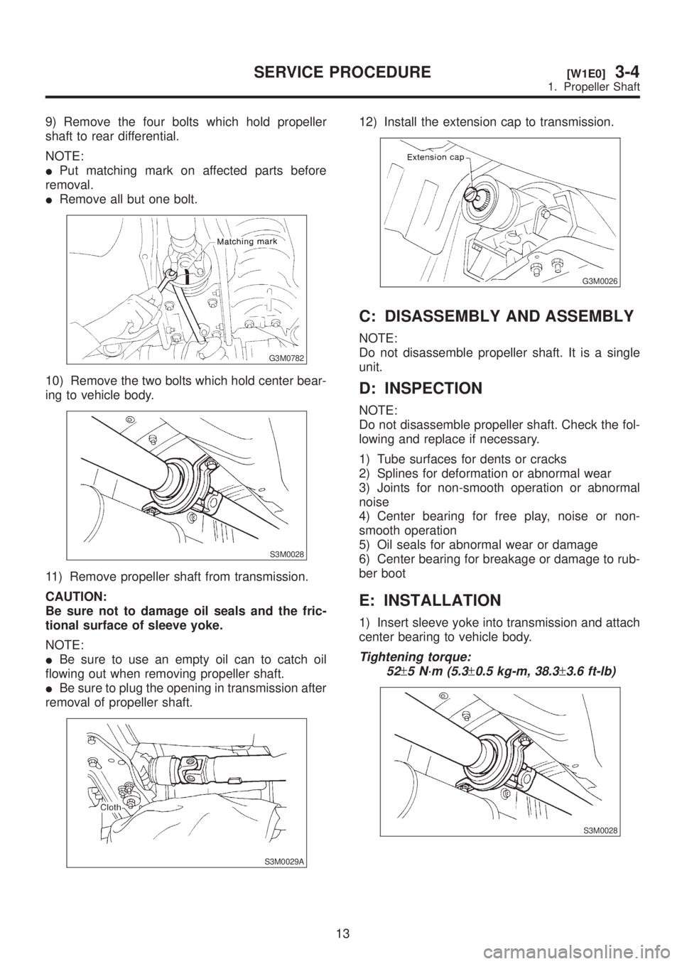
9) Remove the four bolts which hold propeller
shaft to rear differential.
NOTE:
IPut matching mark on affected parts before
removal.
IRemove all but one bolt.
G3M0782
10) Remove the two bolts which hold center bear-
ing to vehicle body.
S3M0028
11) Remove propeller shaft from transmission.
CAUTION:
Be sure not to damage oil seals and the fric-
tional surface of sleeve yoke.
NOTE:
IBe sure to use an empty oil can to catch oil
flowing out when removing propeller shaft.
IBe sure to plug the opening in transmission after
removal of propeller shaft.
S3M0029A
12) Install the extension cap to transmission.
G3M0026
C: DISASSEMBLY AND ASSEMBLY
NOTE:
Do not disassemble propeller shaft. It is a single
unit.
D: INSPECTION
NOTE:
Do not disassemble propeller shaft. Check the fol-
lowing and replace if necessary.
1) Tube surfaces for dents or cracks
2) Splines for deformation or abnormal wear
3) Joints for non-smooth operation or abnormal
noise
4) Center bearing for free play, noise or non-
smooth operation
5) Oil seals for abnormal wear or damage
6) Center bearing for breakage or damage to rub-
ber boot
E: INSTALLATION
1) Insert sleeve yoke into transmission and attach
center bearing to vehicle body.
Tightening torque:
52
±5 N´m (5.3±0.5 kg-m, 38.3±3.6 ft-lb)
S3M0028
13
[W1E0]3-4SERVICE PROCEDURE
1. Propeller Shaft
Page 671 of 1456
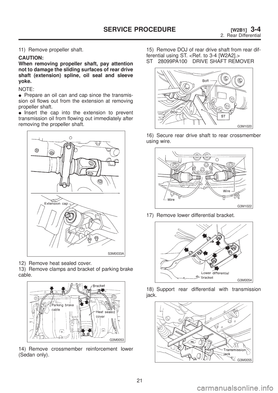
11) Remove propeller shaft.
CAUTION:
When removing propeller shaft, pay attention
not to damage the sliding surfaces of rear drive
shaft (extension) spline, oil seal and sleeve
yoke.
NOTE:
IPrepare an oil can and cap since the transmis-
sion oil flows out from the extension at removing
propeller shaft.
IInsert the cap into the extension to prevent
transmission oil from flowing out immediately after
removing the propeller shaft.
S3M0033A
12) Remove heat sealed cover.
13) Remove clamps and bracket of parking brake
cable.
G3M0053
14) Remove crossmember reinforcement lower
(Sedan only).15) Remove DOJ of rear drive shaft from rear dif-
ferential using ST.
ST 28099PA100 DRIVE SHAFT REMOVER
G3M1020
16) Secure rear drive shaft to rear crossmember
using wire.
G3M1022
17) Remove lower differential bracket.
G3M0054
18) Support rear differential with transmission
jack.
G3M0055
21
[W2B1]3-4SERVICE PROCEDURE
2. Rear Differential
Page 672 of 1456
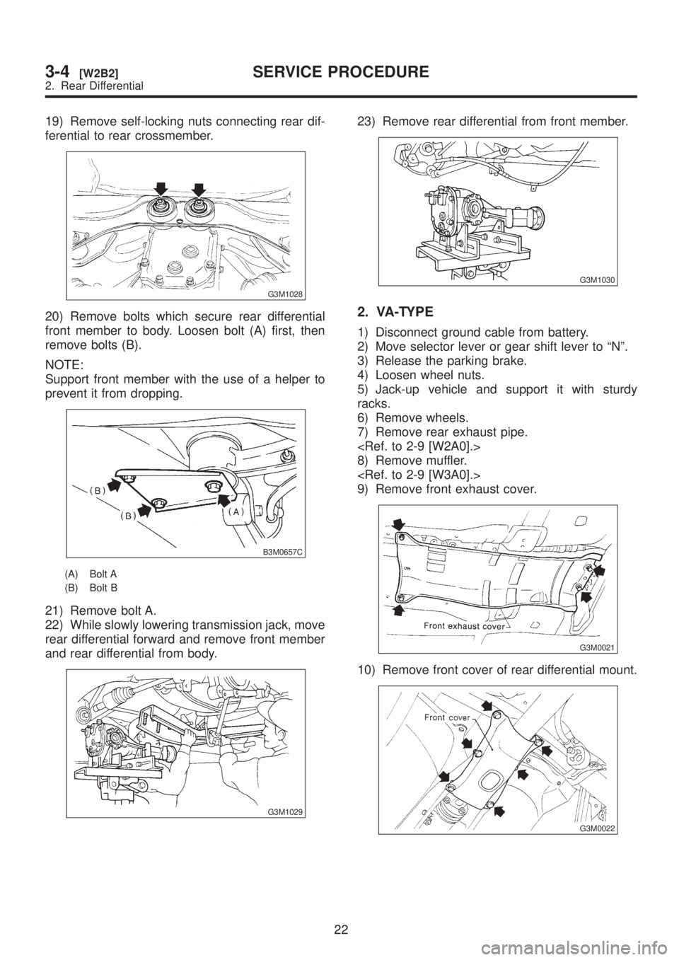
19) Remove self-locking nuts connecting rear dif-
ferential to rear crossmember.
G3M1028
20) Remove bolts which secure rear differential
front member to body. Loosen bolt (A) first, then
remove bolts (B).
NOTE:
Support front member with the use of a helper to
prevent it from dropping.
B3M0657C
(A) Bolt A
(B) Bolt B
21) Remove bolt A.
22) While slowly lowering transmission jack, move
rear differential forward and remove front member
and rear differential from body.
G3M1029
23) Remove rear differential from front member.
G3M1030
2. VA-TYPE
1) Disconnect ground cable from battery.
2) Move selector lever or gear shift lever to ªNº.
3) Release the parking brake.
4) Loosen wheel nuts.
5) Jack-up vehicle and support it with sturdy
racks.
6) Remove wheels.
7) Remove rear exhaust pipe.
8) Remove muffler.
9) Remove front exhaust cover.
G3M0021
10) Remove front cover of rear differential mount.
G3M0022
22
3-4[W2B2]SERVICE PROCEDURE
2. Rear Differential
Page 673 of 1456
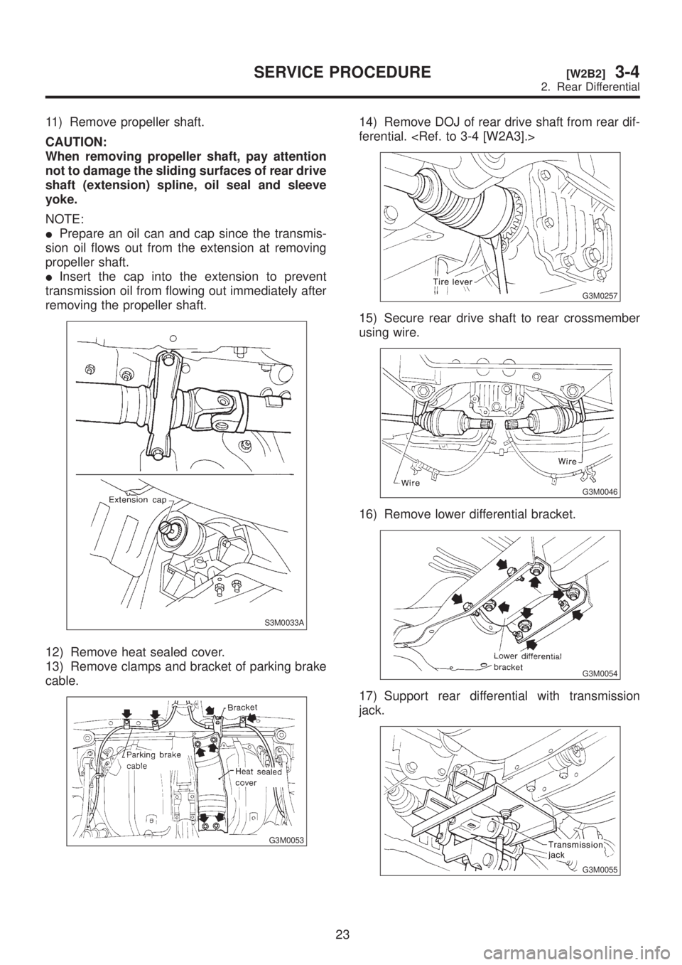
11) Remove propeller shaft.
CAUTION:
When removing propeller shaft, pay attention
not to damage the sliding surfaces of rear drive
shaft (extension) spline, oil seal and sleeve
yoke.
NOTE:
IPrepare an oil can and cap since the transmis-
sion oil flows out from the extension at removing
propeller shaft.
IInsert the cap into the extension to prevent
transmission oil from flowing out immediately after
removing the propeller shaft.
S3M0033A
12) Remove heat sealed cover.
13) Remove clamps and bracket of parking brake
cable.
G3M0053
14) Remove DOJ of rear drive shaft from rear dif-
ferential.
G3M0257
15) Secure rear drive shaft to rear crossmember
using wire.
G3M0046
16) Remove lower differential bracket.
G3M0054
17) Support rear differential with transmission
jack.
G3M0055
23
[W2B2]3-4SERVICE PROCEDURE
2. Rear Differential
Page 674 of 1456
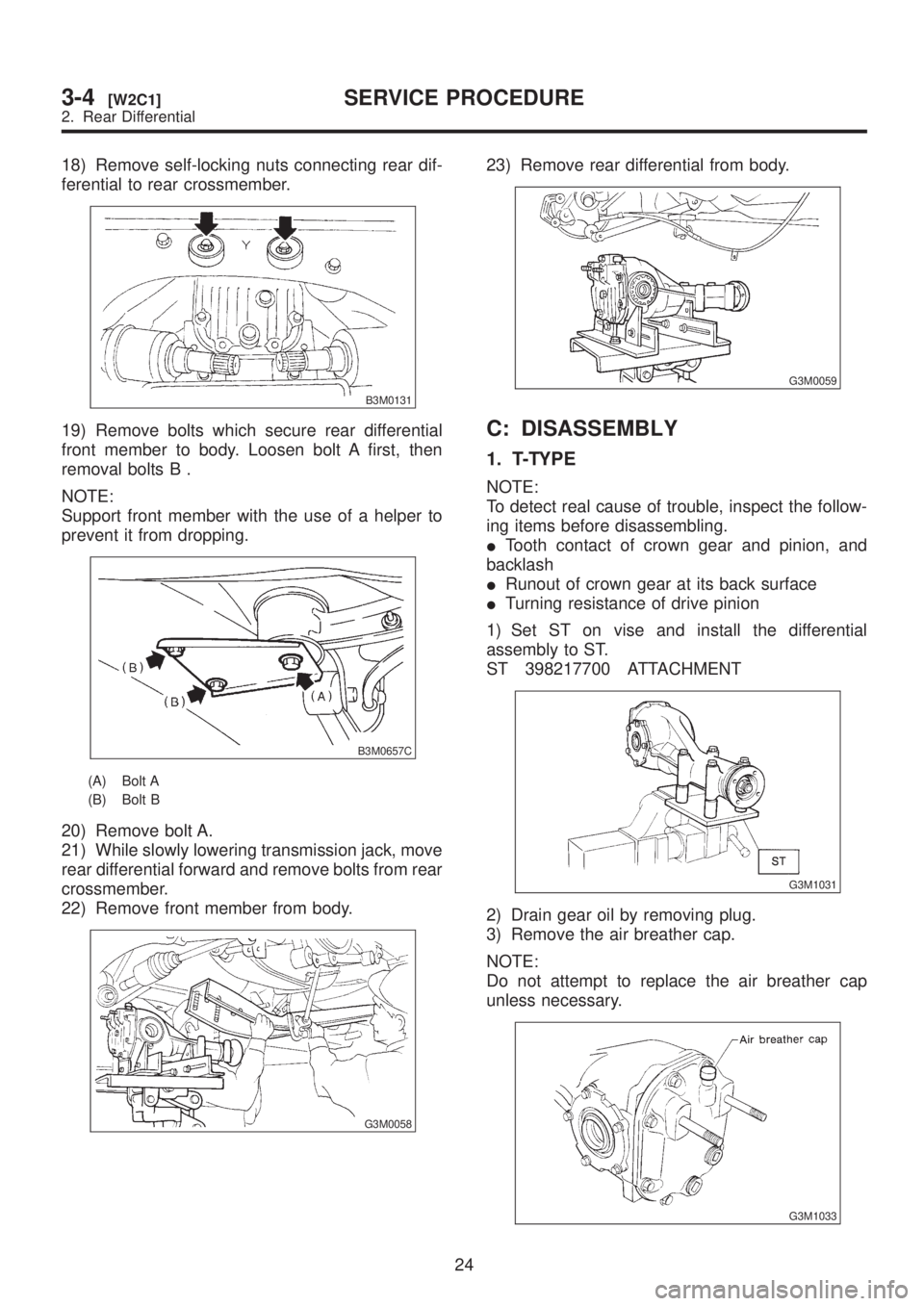
18) Remove self-locking nuts connecting rear dif-
ferential to rear crossmember.
B3M0131
19) Remove bolts which secure rear differential
front member to body. Loosen bolt A first, then
removal bolts B .
NOTE:
Support front member with the use of a helper to
prevent it from dropping.
B3M0657C
(A) Bolt A
(B) Bolt B
20) Remove bolt A.
21) While slowly lowering transmission jack, move
rear differential forward and remove bolts from rear
crossmember.
22) Remove front member from body.
G3M0058
23) Remove rear differential from body.
G3M0059
C: DISASSEMBLY
1. T-TYPE
NOTE:
To detect real cause of trouble, inspect the follow-
ing items before disassembling.
ITooth contact of crown gear and pinion, and
backlash
IRunout of crown gear at its back surface
ITurning resistance of drive pinion
1) Set ST on vise and install the differential
assembly to ST.
ST 398217700 ATTACHMENT
G3M1031
2) Drain gear oil by removing plug.
3) Remove the air breather cap.
NOTE:
Do not attempt to replace the air breather cap
unless necessary.
G3M1033
24
3-4[W2C1]SERVICE PROCEDURE
2. Rear Differential
Page 703 of 1456
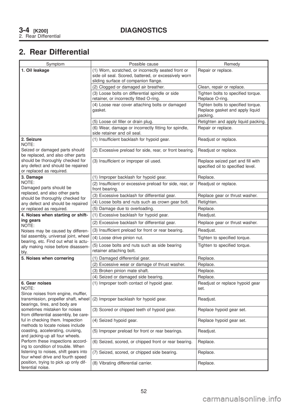
2. Rear Differential
Symptom Possible cause Remedy
1. Oil leakage(1) Worn, scratched, or incorrectly seated front or
side oil seal. Scored, battered, or excessively worn
sliding surface of companion flange.Repair or replace.
(2) Clogged or damaged air breather. Clean, repair or replace.
(3) Loose bolts on differential spindle or side
retainer, or incorrectly fitted O-ring.Tighten bolts to specified torque.
Replace O-ring.
(4) Loose rear cover attaching bolts or damaged
gasket.Tighten bolts to specified torque.
Replace gasket and apply liquid
packing.
(5) Loose oil filler or drain plug. Retighten and apply liquid packing.
(6) Wear, damage or incorrectly fitting for spindle,
side retainer and oil seal.Repair or replace.
2. Seizure
NOTE:
Seized or damaged parts should
be replaced, and also other parts
should be thoroughly checked for
any defect and should be repaired
or replaced as required.(1) Insufficient backlash for hypoid gear. Readjust or replace.
(2) Excessive preload for side, rear, or front bearing. Readjust or replace.
(3) Insufficient or improper oil used. Replace seized part and fill with
specified oil to specified level.
3. Damage
NOTE:
Damaged parts should be
replaced, and also other parts
should be thoroughly checked for
any defect and should be repaired
or replaced as required.(1) Improper backlash for hypoid gear. Replace.
(2) Insufficient or excessive preload for side, rear, or
front bearing.Readjust or replace.
(3) Excessive backlash for differential gear. Replace gear or thrust washer.
(4) Loose bolts and nuts such as crown gear bolt. Retighten.
(5) Damage due to overloading. Replace.
4. Noises when starting or shift-
ing gears
NOTE:
Noises may be caused by differen-
tial assembly, universal joint, wheel
bearing, etc. Find out what is actu-
ally making noise before disassem-
bly.(1) Excessive backlash for hypoid gear. Readjust.
(2) Excessive backlash for differential gear. Replace gear or thrust washer.
(3) Insufficient preload for front or rear bearing. Readjust.
(4) Loose drive pinion nut. Tighten to specified torque.
(5) Loose bolts and nuts such as side bearing
retainer attaching bolt.Tighten to specified torque.
5. Noises when cornering(1) Damaged differential gear. Replace.
(2) Excessive wear or damage of thrust washer. Replace.
(3) Broken pinion mate shaft. Replace.
(4) Seized or damaged side bearing. Replace.
6. Gear noises
NOTE:
Since noises from engine, muffler,
transmission, propeller shaft, wheel
bearings, tires, and body are
sometimes mistaken for noises
from differential assembly, be care-
ful in checking them. Inspection
methods to locate noises include
coasting, accelerating, cruising,
and jacking-up all four wheels.
Perform these inspections accord-
ing to condition of trouble. When
listening to noises, shift gears into
four wheel drive and fourth speed
position, trying to pick up only dif-
ferential noise.(1) Improper tooth contact of hypoid gear. Readjust or replace hypoid gear
set.
(2) Improper backlash for hypoid gear. Readjust.
(3) Scored or chipped teeth of hypoid gear. Replace hypoid gear set.
(4) Seized hypoid gear. Replace hypoid gear set.
(5) Improper preload for front or rear bearings. Readjust.
(6) Seized, scored, or chipped front or rear bearing. Replace.
(7) Seized, scored, or chipped side bearing. Replace.
(8) Vibrating differential carrier. Replace.
52
3-4[K200]DIAGNOSTICS
2. Rear Differential
Page 740 of 1456
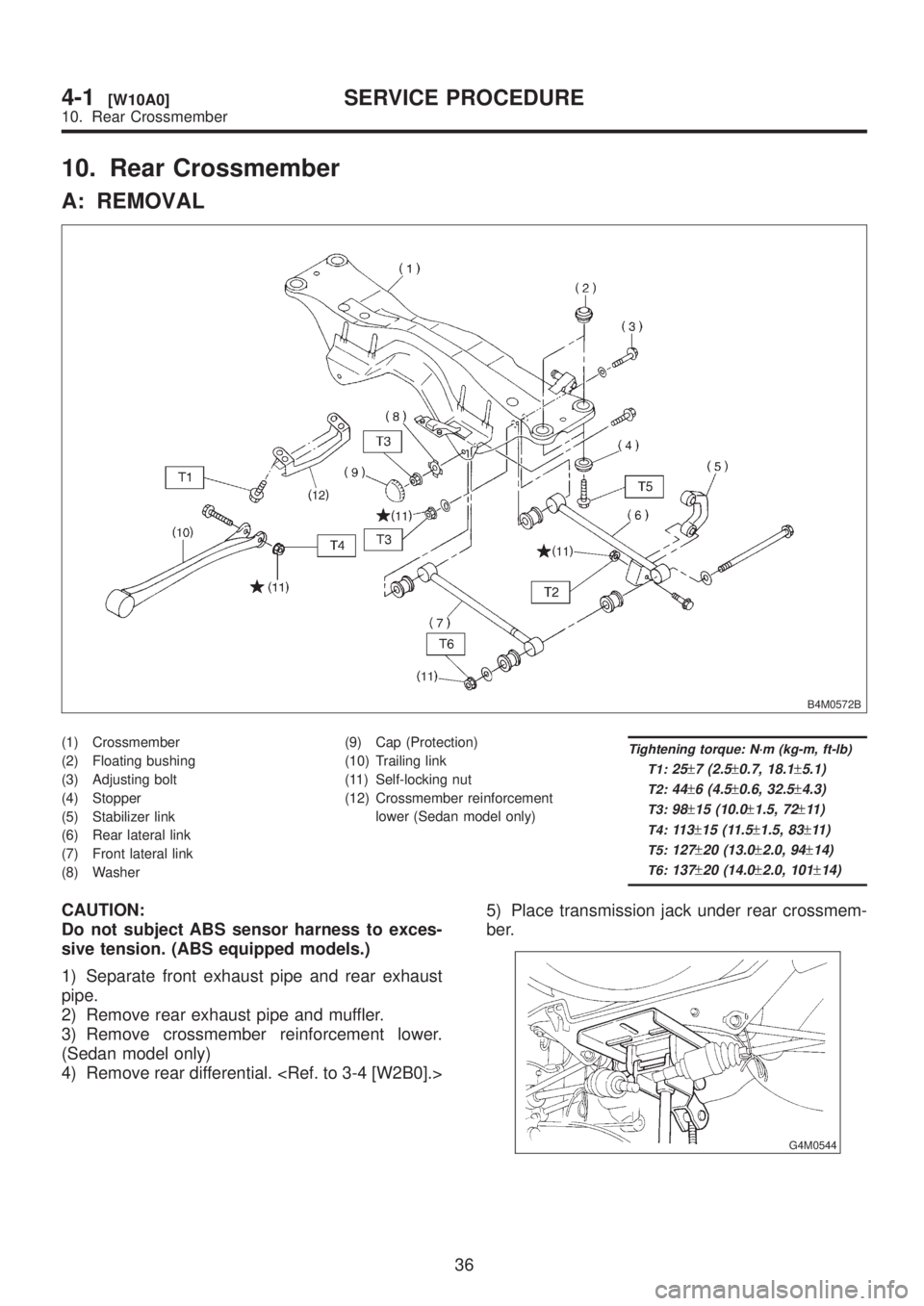
10. Rear Crossmember
A: REMOVAL
B4M0572B
(1) Crossmember
(2) Floating bushing
(3) Adjusting bolt
(4) Stopper
(5) Stabilizer link
(6) Rear lateral link
(7) Front lateral link
(8) Washer(9) Cap (Protection)
(10) Trailing link
(11) Self-locking nut
(12) Crossmember reinforcement
lower (Sedan model only)Tightening torque: N´m (kg-m, ft-lb)
T1:
25±7 (2.5±0.7, 18.1±5.1)
T2:44±6 (4.5±0.6, 32.5±4.3)
T3:98±15 (10.0±1.5, 72±11 )
T4:11 3±15 (11.5±1.5, 83±11 )
T5:127±20 (13.0±2.0, 94±14)
T6:137±20 (14.0±2.0, 101±14)
CAUTION:
Do not subject ABS sensor harness to exces-
sive tension. (ABS equipped models.)
1) Separate front exhaust pipe and rear exhaust
pipe.
2) Remove rear exhaust pipe and muffler.
3) Remove crossmember reinforcement lower.
(Sedan model only)
4) Remove rear differential.
ber.
G4M0544
36
4-1[W10A0]SERVICE PROCEDURE
10. Rear Crossmember
Page 754 of 1456
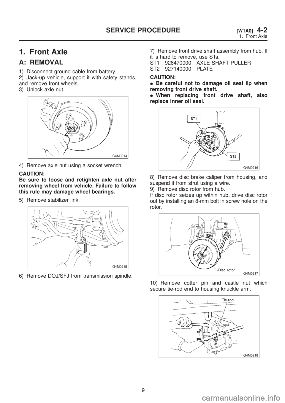
1. Front Axle
A: REMOVAL
1) Disconnect ground cable from battery.
2) Jack-up vehicle, support it with safety stands,
and remove front wheels.
3) Unlock axle nut.
G4M0214
4) Remove axle nut using a socket wrench.
CAUTION:
Be sure to loose and retighten axle nut after
removing wheel from vehicle. Failure to follow
this rule may damage wheel bearings.
5) Remove stabilizer link.
G4M0215
6) Remove DOJ/SFJ from transmission spindle.7) Remove front drive shaft assembly from hub. If
it is hard to remove, use STs.
ST1 926470000 AXLE SHAFT PULLER
ST2 927140000 PLATE
CAUTION:
IBe careful not to damage oil seal lip when
removing front drive shaft.
IWhen replacing front drive shaft, also
replace inner oil seal.
G4M0216
8) Remove disc brake caliper from housing, and
suspend it from strut using a wire.
9) Remove disc rotor from hub.
If disc rotor seizes up within hub, drive disc rotor
out by installing an 8-mm bolt in screw hole on the
rotor.
G4M0217
10) Remove cotter pin and castle nut which
secure tie-rod end to housing knuckle arm.
G4M0218
9
[W1A0]4-2SERVICE PROCEDURE
1. Front Axle
Page 768 of 1456
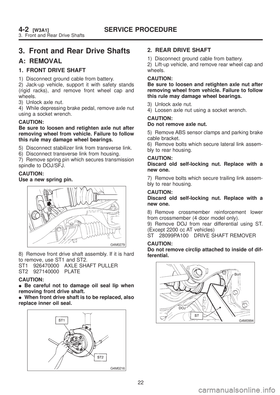
3. Front and Rear Drive Shafts
A: REMOVAL
1. FRONT DRIVE SHAFT
1) Disconnect ground cable from battery.
2) Jack-up vehicle, support it with safety stands
(rigid racks), and remove front wheel cap and
wheels.
3) Unlock axle nut.
4) While depressing brake pedal, remove axle nut
using a socket wrench.
CAUTION:
Be sure to loosen and retighten axle nut after
removing wheel from vehicle. Failure to follow
this rule may damage wheel bearings.
5) Disconnect stabilizer link from transverse link.
6) Disconnect transverse link from housing.
7) Remove spring pin which secures transmission
spindle to DOJ/SFJ.
CAUTION:
Use a new spring pin.
G4M0279
8) Remove front drive shaft assembly. If it is hard
to remove, use ST1 and ST2.
ST1 926470000 AXLE SHAFT PULLER
ST2 927140000 PLATE
CAUTION:
IBe careful not to damage oil seal lip when
removing front drive shaft.
IWhen front drive shaft is to be replaced, also
replace inner oil seal.
G4M0216
2. REAR DRIVE SHAFT
1) Disconnect ground cable from battery.
2) Lift-up vehicle, and remove rear wheel cap and
wheels.
CAUTION:
Be sure to loosen and retighten axle nut after
removing wheel from vehicle. Failure to follow
this rule may damage wheel bearings.
3) Unlock axle nut.
4) Loosen axle nut using a socket wrench.
CAUTION:
Do not remove axle nut.
5) Remove ABS sensor clamps and parking brake
cable bracket.
6) Remove bolts which secure lateral link assem-
bly to rear housing.
CAUTION:
Discard old self-locking nut. Replace with a
new one.
7) Remove bolts which secure trailing link assem-
bly to rear housing.
CAUTION:
Discard old self-locking nut. Replace with a
new one.
8) Remove crossmember reinforcement lower
from crossmember (4 door model only).
9) Remove DOJ from rear differential using ST.
(Except 2200 cc AT vehicles)
ST 28099PA100 DRIVE SHAFT REMOVER
CAUTION:
Do not remove circlip attached to inside of dif-
ferential.
G4M0994
22
4-2[W3A1]SERVICE PROCEDURE
3. Front and Rear Drive Shafts