rear SUBARU LEGACY 1999 Service Repair Manual
[x] Cancel search | Manufacturer: SUBARU, Model Year: 1999, Model line: LEGACY, Model: SUBARU LEGACY 1999Pages: 1456, PDF Size: 59.93 MB
Page 1241 of 1456
B6M0238
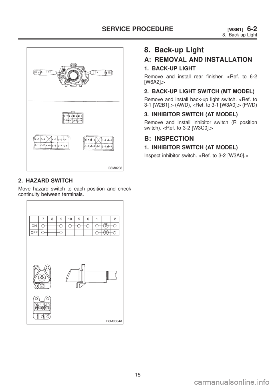
2. HAZARD SWITCH
Move hazard switch to each position and check
continuity between terminals.
B6M0834A
8. Back-up Light
A: REMOVAL AND INSTALLATION
1. BACK-UP LIGHT
Remove and install rear finisher.
2. BACK-UP LIGHT SWITCH (MT MODEL)
Remove and install back-up light switch.
3. INHIBITOR SWITCH (AT MODEL)
Remove and install inhibitor switch (R position
switch).
B: INSPECTION
1. INHIBITOR SWITCH (AT MODEL)
Inspect inhibitor switch.
15
[W8B1]6-2SERVICE PROCEDURE
8. Back-up Light
Page 1242 of 1456
B6M0238
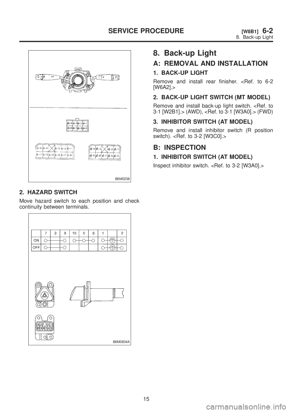
2. HAZARD SWITCH
Move hazard switch to each position and check
continuity between terminals.
B6M0834A
8. Back-up Light
A: REMOVAL AND INSTALLATION
1. BACK-UP LIGHT
Remove and install rear finisher.
2. BACK-UP LIGHT SWITCH (MT MODEL)
Remove and install back-up light switch.
3. INHIBITOR SWITCH (AT MODEL)
Remove and install inhibitor switch (R position
switch).
B: INSPECTION
1. INHIBITOR SWITCH (AT MODEL)
Inspect inhibitor switch.
15
[W8B1]6-2SERVICE PROCEDURE
8. Back-up Light
Page 1243 of 1456
9. Room Light and Door Switch
A: REMOVAL AND INSTALLATION
1. ROOM LIGHT
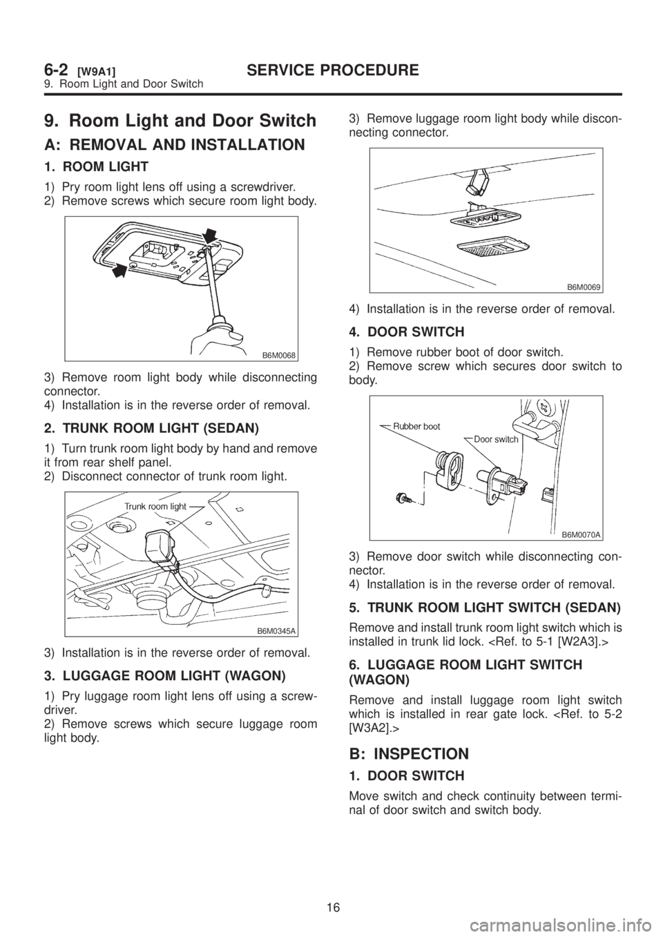
1) Pry room light lens off using a screwdriver.
2) Remove screws which secure room light body.
B6M0068
3) Remove room light body while disconnecting
connector.
4) Installation is in the reverse order of removal.
2. TRUNK ROOM LIGHT (SEDAN)
1) Turn trunk room light body by hand and remove
it from rear shelf panel.
2) Disconnect connector of trunk room light.
B6M0345A
3) Installation is in the reverse order of removal.
3. LUGGAGE ROOM LIGHT (WAGON)
1) Pry luggage room light lens off using a screw-
driver.
2) Remove screws which secure luggage room
light body.3) Remove luggage room light body while discon-
necting connector.
B6M0069
4) Installation is in the reverse order of removal.
4. DOOR SWITCH
1) Remove rubber boot of door switch.
2) Remove screw which secures door switch to
body.
B6M0070A
3) Remove door switch while disconnecting con-
nector.
4) Installation is in the reverse order of removal.
5. TRUNK ROOM LIGHT SWITCH (SEDAN)
Remove and install trunk room light switch which is
installed in trunk lid lock.
6. LUGGAGE ROOM LIGHT SWITCH
(WAGON)
Remove and install luggage room light switch
which is installed in rear gate lock.
B: INSPECTION
1. DOOR SWITCH
Move switch and check continuity between termi-
nal of door switch and switch body.
16
6-2[W9A1]SERVICE PROCEDURE
9. Room Light and Door Switch
Page 1250 of 1456
12. Rear Wiper and Washer
A: ADJUSTMENT
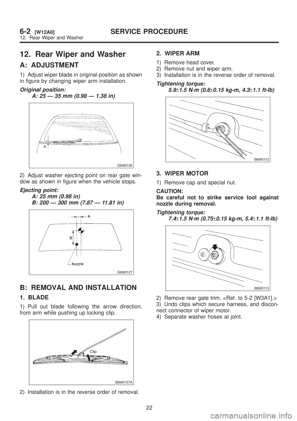
1) Adjust wiper blade in original position as shown
in figure by changing wiper arm installation.
Original position:
A: 25 Ð 35 mm (0.98 Ð 1.38 in)
G6M0126
2) Adjust washer ejecting point on rear gate win-
dow as shown in figure when the vehicle stops.
Ejecting point:
A: 25 mm (0.98 in)
B: 200 Ð 300 mm (7.87 Ð 11.81 in)
G6M0127
B: REMOVAL AND INSTALLATION
1. BLADE
1) Pull out blade following the arrow direction,
from arm while pushing up locking clip.
B6M0107A
2) Installation is in the reverse order of removal.
2. WIPER ARM
1) Remove head cover.
2) Remove nut and wiper arm.
3) Installation is in the reverse order of removal.
Tightening torque:
5.9
±1.5 N´m (0.6±0.15 kg-m, 4.3±1.1 ft-lb)
B6M0112
3. WIPER MOTOR
1) Remove cap and special nut.
CAUTION:
Be careful not to strike service tool against
nozzle during removal.
Tightening torque:
7.4
±1.5 N´m (0.75±0.15 kg-m, 5.4±1.1 ft-lb)
B6M0113
2) Remove rear gate trim.
3) Undo clips which secure harness, and discon-
nect connector of wiper motor.
4) Separate washer hoses at joint.
22
6-2[W12A0]SERVICE PROCEDURE
12. Rear Wiper and Washer
Page 1251 of 1456
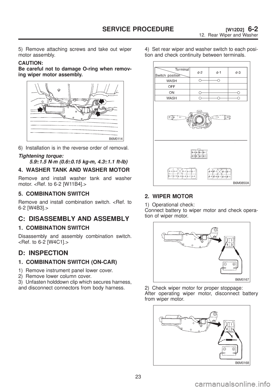
5) Remove attaching screws and take out wiper
motor assembly.
CAUTION:
Be careful not to damage O-ring when remov-
ing wiper motor assembly.
B6M0114
6) Installation is in the reverse order of removal.
Tightening torque:
5.9
±1.5 N´m (0.6±0.15 kg-m, 4.3±1.1 ft-lb)
4. WASHER TANK AND WASHER MOTOR
Remove and install washer tank and washer
motor.
5. COMBINATION SWITCH
Remove and install combination switch.
C: DISASSEMBLY AND ASSEMBLY
1. COMBINATION SWITCH
Disassembly and assembly combination switch.
D: INSPECTION
1. COMBINATION SWITCH (ON-CAR)
1) Remove instrument panel lower cover.
2) Remove lower column cover.
3) Unfasten holddown clip which secures harness,
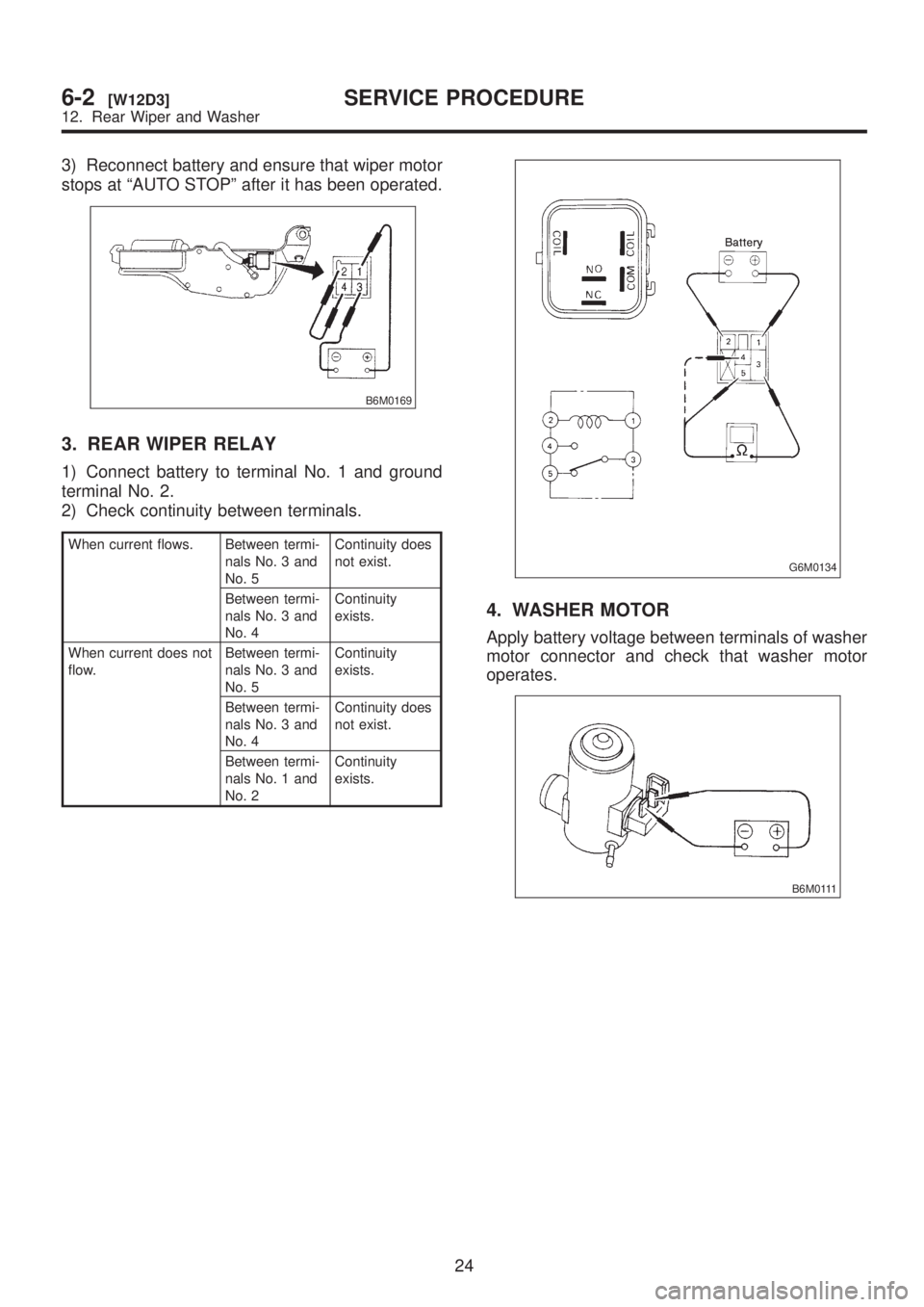
and disconnect connectors from body harness.4) Set rear wiper and washer switch to each posi-
tion and check continuity between terminals.
B6M0850A
2. WIPER MOTOR
1) Operational check:
Connect battery to wiper motor and check opera-
tion of wiper motor.
B6M0167
2) Check wiper motor for proper stoppage:
After operating wiper motor, disconnect battery
from wiper motor.
B6M0168
23
[W12D2]6-2SERVICE PROCEDURE
12. Rear Wiper and Washer
Page 1252 of 1456
3) Reconnect battery and ensure that wiper motor
stops at ªAUTO STOPº after it has been operated.
B6M0169
3. REAR WIPER RELAY
1) Connect battery to terminal No. 1 and ground
terminal No. 2.
2) Check continuity between terminals.
When current flows. Between termi-
nals No. 3 and
No. 5Continuity does
not exist.
Between termi-
nals No. 3 and
No. 4Continuity
exists.
When current does not
flow.Between termi-
nals No. 3 and
No. 5Continuity
exists.
Between termi-
nals No. 3 and
No. 4Continuity does
not exist.
Between termi-
nals No. 1 and
No. 2Continuity
exists.
G6M0134
4. WASHER MOTOR
Apply battery voltage between terminals of washer
motor connector and check that washer motor
operates.
B6M0111
24
6-2[W12D3]SERVICE PROCEDURE
12. Rear Wiper and Washer
Page 1253 of 1456
13. Rear Window Defogger
A: REMOVAL AND INSTALLATION
1. DEFOGGER SWITCH
1) Remove screws which secure meter visor.
2) Remove meter visor from instrument panel
while disconnecting connectors.
3) Remove rear window defogger switch from
meter visor.
4) Installation is in the reverse order of removal.
B: INSPECTION
1. DEFOGGER SWITCH
Move rear window defogger switch to each posi-
tion and check continuity between terminals.
B6M0851A
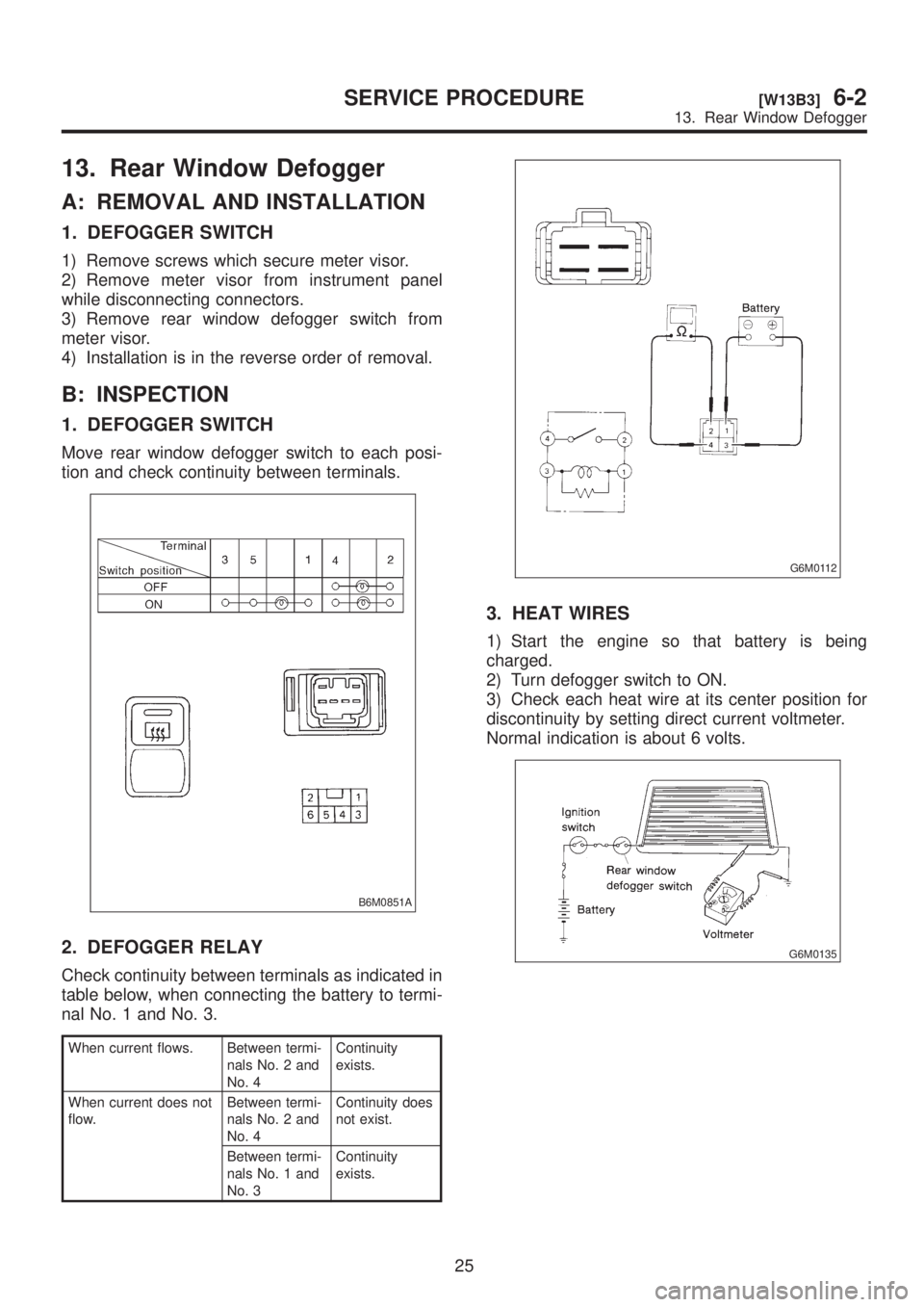
2. DEFOGGER RELAY
Check continuity between terminals as indicated in
table below, when connecting the battery to termi-
nal No. 1 and No. 3.
When current flows. Between termi-
nals No. 2 and
No. 4Continuity
exists.
When current does not
flow.Between termi-
nals No. 2 and
No. 4Continuity does
not exist.
Between termi-
nals No. 1 and
No. 3Continuity
exists.
G6M0112
3. HEAT WIRES
1) Start the engine so that battery is being
charged.
2) Turn defogger switch to ON.
3) Check each heat wire at its center position for
discontinuity by setting direct current voltmeter.
Normal indication is about 6 volts.
G6M0135
25
[W13B3]6-2SERVICE PROCEDURE
13. Rear Window Defogger
Page 1254 of 1456
NOTE:
When measuring voltage, wind a piece of tin foil
around the tip of the tester probe and press the foil
against the wire with your finger.
G6M0136
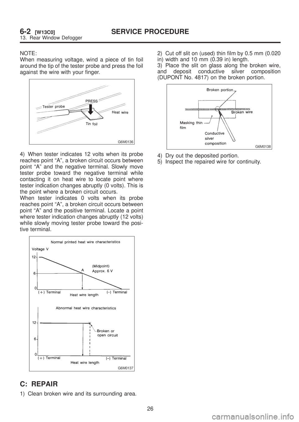
4) When tester indicates 12 volts when its probe
reaches point ªAº, a broken circuit occurs between
point ªAº and the negative terminal. Slowly move
tester probe toward the negative terminal while
contacting it on heat wire to locate point where
tester indication changes abruptly (0 volts). This is
the point where a broken circuit occurs.
When tester indicates 0 volts when its probe
reaches point ªAº, a broken circuit occurs between
point ªAº and the positive terminal. Locate a point
where tester indication changes abruptly (12 volts)
while slowly moving tester probe toward the posi-
tive terminal.
G6M0137
C: REPAIR
1) Clean broken wire and its surrounding area.2) Cut off slit on (used) thin film by 0.5 mm (0.020
in) width and 10 mm (0.39 in) length.
3) Place the slit on glass along the broken wire,
and deposit conductive silver composition
(DUPONT No. 4817) on the broken portion.
G6M0138
4) Dry out the deposited portion.
5) Inspect the repaired wire for continuity.
26
6-2[W13C0]SERVICE PROCEDURE
13. Rear Window Defogger
Page 1256 of 1456
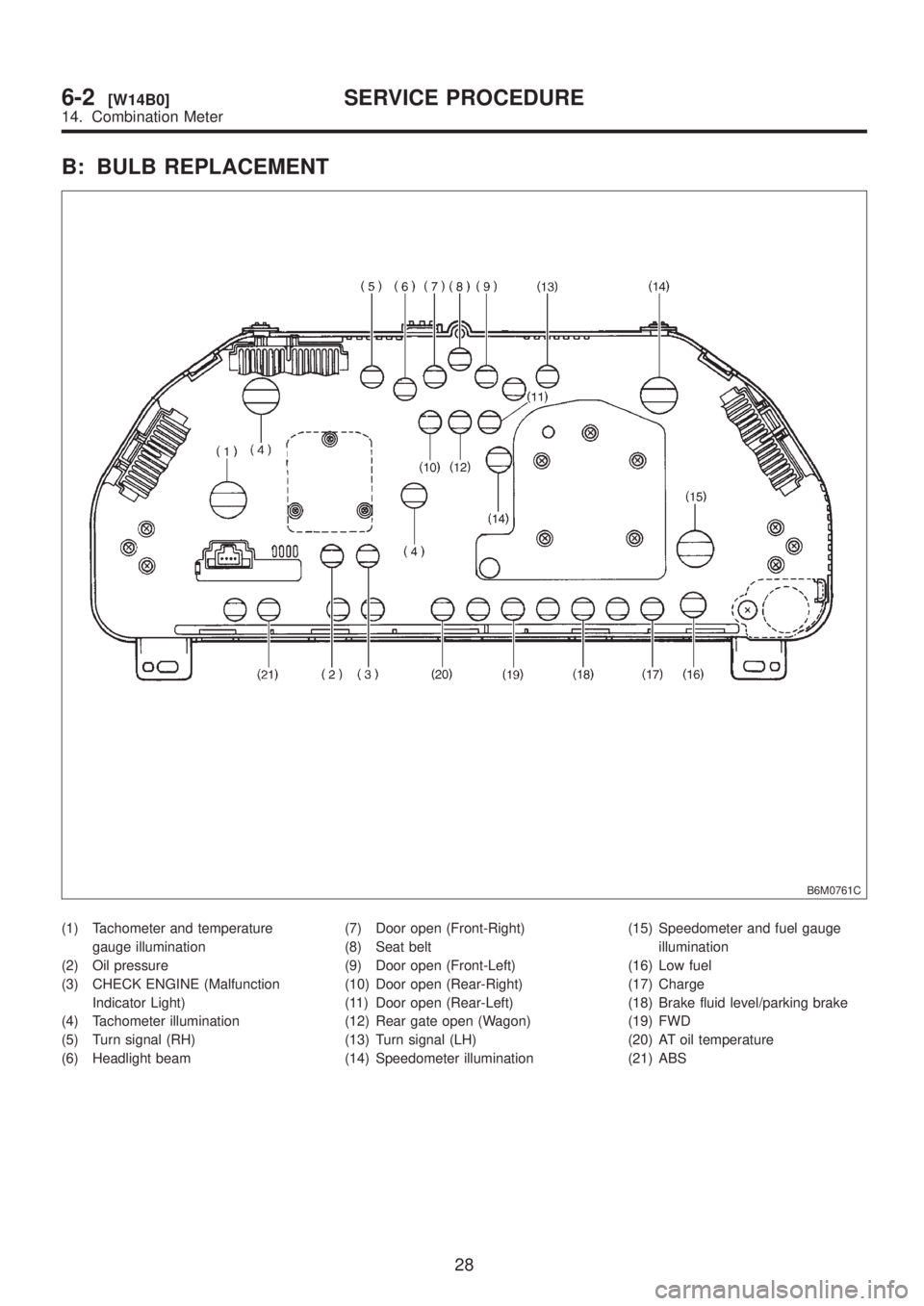
B: BULB REPLACEMENT
B6M0761C
(1) Tachometer and temperature
gauge illumination
(2) Oil pressure
(3) CHECK ENGINE (Malfunction
Indicator Light)
(4) Tachometer illumination
(5) Turn signal (RH)
(6) Headlight beam(7) Door open (Front-Right)
(8) Seat belt
(9) Door open (Front-Left)
(10) Door open (Rear-Right)
(11) Door open (Rear-Left)
(12) Rear gate open (Wagon)
(13) Turn signal (LH)
(14) Speedometer illumination(15) Speedometer and fuel gauge
illumination
(16) Low fuel
(17) Charge
(18) Brake fluid level/parking brake
(19) FWD
(20) AT oil temperature
(21) ABS
28
6-2[W14B0]SERVICE PROCEDURE
14. Combination Meter
Page 1262 of 1456
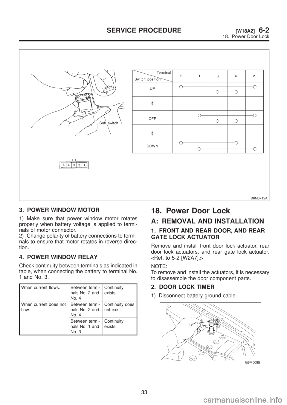
B6M0712A
3. POWER WINDOW MOTOR
1) Make sure that power window motor rotates
properly when battery voltage is applied to termi-
nals of motor connector.
2) Change polarity of battery connections to termi-
nals to ensure that motor rotates in reverse direc-
tion.
4. POWER WINDOW RELAY
Check continuity between terminals as indicated in
table, when connecting the battery to terminal No.
1 and No. 3.
When current flows. Between termi-
nals No. 2 and
No. 4Continuity
exists.
When current does not
flow.Between termi-
nals No. 2 and
No. 4Continuity does
not exist.
Between termi-
nals No. 1 and
No. 3Continuity
exists.
18. Power Door Lock
A: REMOVAL AND INSTALLATION
1. FRONT AND REAR DOOR, AND REAR
GATE LOCK ACTUATOR
Remove and install front door lock actuator, rear
door lock actuators, and rear gate lock actuator.
NOTE:
To remove and install the actuators, it is necessary
to disassemble the door component parts.
2. DOOR LOCK TIMER
1) Disconnect battery ground cable.
G6M0095
33
[W18A2]6-2SERVICE PROCEDURE
18. Power Door Lock