Wheel bearing SUBARU LEGACY 1999 Service Owner's Guide
[x] Cancel search | Manufacturer: SUBARU, Model Year: 1999, Model line: LEGACY, Model: SUBARU LEGACY 1999Pages: 1456, PDF Size: 59.93 MB
Page 782 of 1456
4. Replacement of Front SFJ,
DOJ and BJ Boots
A: REMOVAL
1) Disconnect ground cable from battery.
2) Jack-up vehicle, support it with safety stands
(rigid racks), and remove front wheel cap and
wheels.
NOTE:
Do not remove axle nut.
3) Remove stabilizer link.
4) Disconnect transverse link from housing.
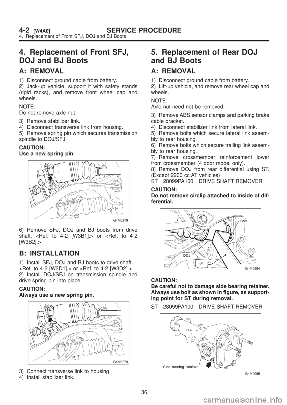
5) Remove spring pin which secures transmission
spindle to DOJ/SFJ.
CAUTION:
Use a new spring pin.
G4M0279
6) Remove SFJ, DOJ and BJ boots from drive
shaft.
B: INSTALLATION
1) Install SFJ, DOJ and BJ boots to drive shaft.
2) Install DOJ/SFJ on transmission spindle and
drive spring pin into place.
CAUTION:
Always use a new spring pin.
G4M0279
3) Connect transverse link to housing.
4) Install stabilizer link.
5. Replacement of Rear DOJ
and BJ Boots
A: REMOVAL
1) Disconnect ground cable from battery.
2) Lift-up vehicle, and remove rear wheel cap and
wheels.
NOTE:
Axle nut need not be removed.
3) Remove ABS sensor clamps and parking brake
cable bracket.
4) Disconnect stabilizer link from lateral link.
5) Remove bolts which secure lateral link assem-
bly to rear housing.
6) Remove bolts which secure trailing link assem-
bly to rear housing.
7) Remove crossmember reinforcement lower
from crossmember (4 door model only).
8) Remove DOJ from rear differential using ST.
(Except 2200 cc AT vehicles)
ST 28099PA100 DRIVE SHAFT REMOVER
CAUTION:
Do not remove circlip attached to inside of dif-
ferential.
G4M0994
CAUTION:
Be careful not to damage side bearing retainer.
Always use bolt as shown in figure, as support-
ing point for ST during removal.
ST 28099PA100 DRIVE SHAFT REMOVER
G4M0995
36
4-2[W4A0]SERVICE PROCEDURE
4. Replacement of Front SFJ, DOJ and BJ Boots
Page 783 of 1456
4. Replacement of Front SFJ,
DOJ and BJ Boots
A: REMOVAL
1) Disconnect ground cable from battery.
2) Jack-up vehicle, support it with safety stands
(rigid racks), and remove front wheel cap and
wheels.
NOTE:
Do not remove axle nut.
3) Remove stabilizer link.
4) Disconnect transverse link from housing.
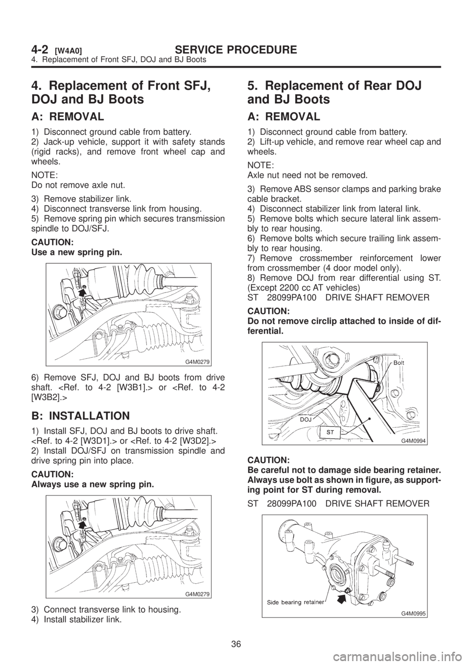
5) Remove spring pin which secures transmission
spindle to DOJ/SFJ.
CAUTION:
Use a new spring pin.
G4M0279
6) Remove SFJ, DOJ and BJ boots from drive
shaft.
B: INSTALLATION
1) Install SFJ, DOJ and BJ boots to drive shaft.
2) Install DOJ/SFJ on transmission spindle and
drive spring pin into place.
CAUTION:
Always use a new spring pin.
G4M0279
3) Connect transverse link to housing.
4) Install stabilizer link.
5. Replacement of Rear DOJ
and BJ Boots
A: REMOVAL
1) Disconnect ground cable from battery.
2) Lift-up vehicle, and remove rear wheel cap and
wheels.
NOTE:
Axle nut need not be removed.
3) Remove ABS sensor clamps and parking brake
cable bracket.
4) Disconnect stabilizer link from lateral link.
5) Remove bolts which secure lateral link assem-
bly to rear housing.
6) Remove bolts which secure trailing link assem-
bly to rear housing.
7) Remove crossmember reinforcement lower
from crossmember (4 door model only).
8) Remove DOJ from rear differential using ST.
(Except 2200 cc AT vehicles)
ST 28099PA100 DRIVE SHAFT REMOVER
CAUTION:
Do not remove circlip attached to inside of dif-
ferential.
G4M0994
CAUTION:
Be careful not to damage side bearing retainer.
Always use bolt as shown in figure, as support-
ing point for ST during removal.
ST 28099PA100 DRIVE SHAFT REMOVER
G4M0995
36
4-2[W4A0]SERVICE PROCEDURE
4. Replacement of Front SFJ, DOJ and BJ Boots
Page 805 of 1456
CAUTION:
Insert roll connector guide pin into guide hole
on lower end of surface of steering wheel to
prevent damage.
Draw out airbag system connector, horn con-
nector and cruise control connectors from
guide hole of steering wheel lower end. (with
airbag model)
8) Install airbag module to steering wheel. (with
airbag model)
WARNING:
Always refer to 5-5 Supplemental Restraint
System before performing the service opera-
tion.
Steering System) [LHD model]
A: REMOVAL
NOTE:
For disassembly and assembly of gearbox unit,
refer to section Control Valve (Power Steering
Gearbox) [LHD model].
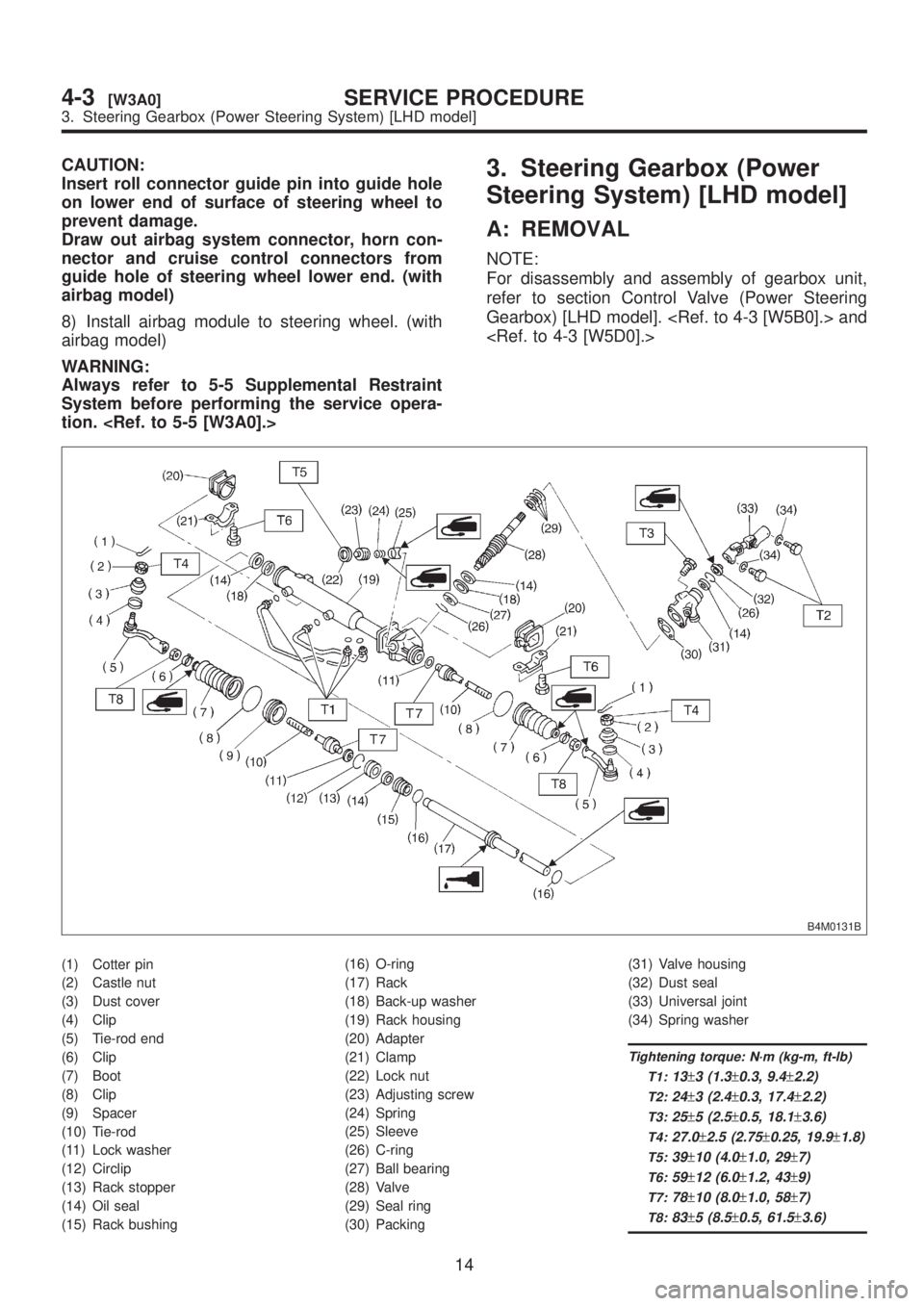
B4M0131B
(1) Cotter pin
(2) Castle nut
(3) Dust cover
(4) Clip
(5) Tie-rod end
(6) Clip
(7) Boot
(8) Clip
(9) Spacer
(10) Tie-rod
(11) Lock washer
(12) Circlip
(13) Rack stopper
(14) Oil seal
(15) Rack bushing(16) O-ring
(17) Rack
(18) Back-up washer
(19) Rack housing
(20) Adapter
(21) Clamp
(22) Lock nut
(23) Adjusting screw
(24) Spring
(25) Sleeve
(26) C-ring
(27) Ball bearing
(28) Valve
(29) Seal ring
(30) Packing(31) Valve housing
(32) Dust seal
(33) Universal joint
(34) Spring washer
Tightening torque: N´m (kg-m, ft-lb)
T1:
13±3 (1.3±0.3, 9.4±2.2)
T2:24±3 (2.4±0.3, 17.4±2.2)
T3:25±5 (2.5±0.5, 18.1±3.6)
T4:27.0±2.5 (2.75±0.25, 19.9±1.8)
T5:39±10 (4.0±1.0, 29±7)
T6:59±12 (6.0±1.2, 43±9)
T7:78±10 (8.0±1.0, 58±7)
T8:83±5 (8.5±0.5, 61.5±3.6)
14
4-3[W3A0]SERVICE PROCEDURE
3. Steering Gearbox (Power Steering System) [LHD model]
Page 806 of 1456
CAUTION:
Insert roll connector guide pin into guide hole
on lower end of surface of steering wheel to
prevent damage.
Draw out airbag system connector, horn con-
nector and cruise control connectors from
guide hole of steering wheel lower end. (with
airbag model)
8) Install airbag module to steering wheel. (with
airbag model)
WARNING:
Always refer to 5-5 Supplemental Restraint
System before performing the service opera-
tion.
Steering System) [LHD model]
A: REMOVAL
NOTE:
For disassembly and assembly of gearbox unit,
refer to section Control Valve (Power Steering
Gearbox) [LHD model].
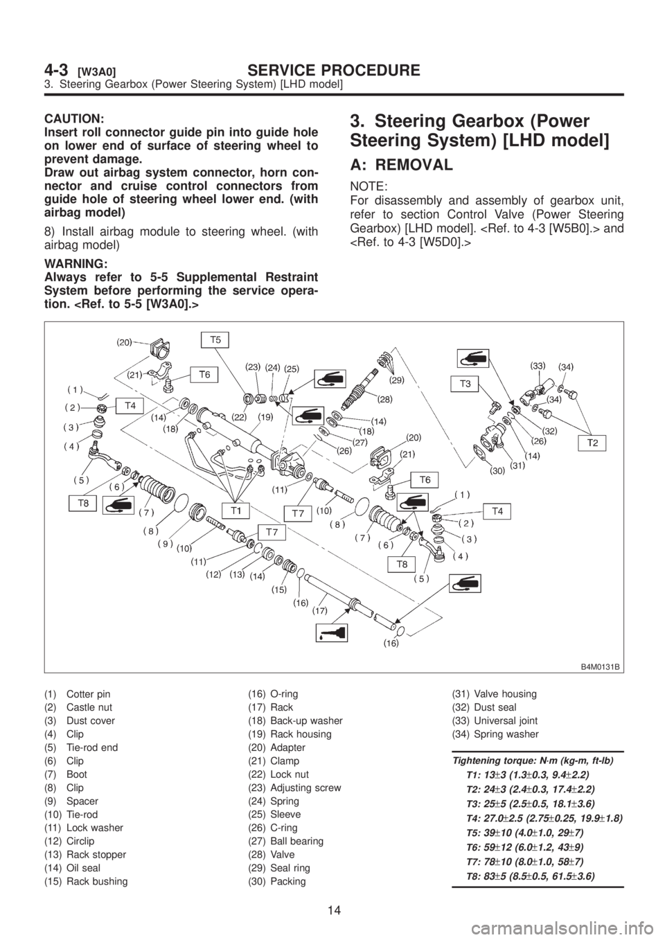
B4M0131B
(1) Cotter pin
(2) Castle nut
(3) Dust cover
(4) Clip
(5) Tie-rod end
(6) Clip
(7) Boot
(8) Clip
(9) Spacer
(10) Tie-rod
(11) Lock washer
(12) Circlip
(13) Rack stopper
(14) Oil seal
(15) Rack bushing(16) O-ring
(17) Rack
(18) Back-up washer
(19) Rack housing
(20) Adapter
(21) Clamp
(22) Lock nut
(23) Adjusting screw
(24) Spring
(25) Sleeve
(26) C-ring
(27) Ball bearing
(28) Valve
(29) Seal ring
(30) Packing(31) Valve housing
(32) Dust seal
(33) Universal joint
(34) Spring washer
Tightening torque: N´m (kg-m, ft-lb)
T1:
13±3 (1.3±0.3, 9.4±2.2)
T2:24±3 (2.4±0.3, 17.4±2.2)
T3:25±5 (2.5±0.5, 18.1±3.6)
T4:27.0±2.5 (2.75±0.25, 19.9±1.8)
T5:39±10 (4.0±1.0, 29±7)
T6:59±12 (6.0±1.2, 43±9)
T7:78±10 (8.0±1.0, 58±7)
T8:83±5 (8.5±0.5, 61.5±3.6)
14
4-3[W3A0]SERVICE PROCEDURE
3. Steering Gearbox (Power Steering System) [LHD model]
Page 869 of 1456
![SUBARU LEGACY 1999 Service Owners Guide Trouble Possible cause Corrective action
Rattling noise (intermittent)
While engine is running.Interference with adjacent parts Check clearance.
Correct if necessary.
<Ref. to 4-3 [K1F0].>
Loosened in](/img/17/57435/w960_57435-868.png "SUBARU LEGACY 1999 Service Owners Guide Trouble Possible cause Corrective action
Rattling noise (intermittent)
While engine is running.Interference with adjacent parts Check clearance.
Correct if necessary.
<Ref. to 4-3 [K1F0].>
Loosened in")
Trouble Possible cause Corrective action
Rattling noise (intermittent)
While engine is running.Interference with adjacent parts Check clearance.
Correct if necessary.
Loosened installation of oil pump, oil tank, pump bracket, gear-
box or crossmemberRetighten.
Loosened installation of oil pump pulley or other pulley(s) Retighten.
Loosened linkage or play of steering or suspension
Loosened tightening of joint or steering columnRetighten or replace.
Sound generates from the inside of gearbox or oil pump. Replace the gearbox or oil
pump.
Knocking
When turning steering wheel
in both direction with small
angle repeatedly at engine
ON or OFF.Excessive backlash
Loosened lock nut for adjusting backlashAdjust and retighten.
Loosened tightening or play of tie-rod, tie-rod end Retighten or replace.
Grinding noise (continuous)
While engine is running.Vane pump aeration Inspect and retighten fluid line
connection.
Refill fluid and vent air.
Vane pump seizing Replace oil pump.
Pulley bearing seizing of oil pump Replace oil pump.
Folded hose, flat pipe Replace.
Squeal, squeak (intermittent
or continuous)
While engine is running.Maladjustment of pulley belt
Damaged or charged pulley belt
Unequal length of pulley beltsAdjust or replace.
(Replace two belts as a set.)
Run out or soilage of V-groove surface of oil pump pulley Clean or replace.
Sizzling noise (continuous)
While engine is running.Fluid aeration Fix wrong part causing aera-
tion.
Replace fluid and vent air.
Damaged pipe of gearbox Replace pipe.
Abnormal inside of hose or pipe
Flat hose or pipeRectify or replace.
Abnormal inside of oil tank Replace.
Removed oil tank cap Install cap.
Whistle (continuous)
While engine is running.Abnormal pipe of gearbox or abnormal inside of hose Replace bad parts of gearbox
or hose.
Whine or growl (continuous or
intermittent)
While engine is running with/
without steering turned.Loosened installation of oil pump, oil pump bracket Retighten.
Abnormal inside of oil pump, hose Replace oil pump, hose, if the
noise can be heard when run-
ning as well as stand still.
Torque converter growl air conditioner compression growl Remove power steering pul-
ley belt and confirm.
Creaking noise (intermittent)
While engine is running with
steering turned.Abnormal inside of gearbox Replace bad parts of gear-
box.
Abnormal bearing for steering shaft Apply grease or replace.
Generates when turning steering wheel with brake (service or
parking) applied.If the noise goes off when
brake is released, it is normal.
Vibration
While engine is running with/
without steering turned.Too low engine speed at start Adjust and instruct custom-
ers.
Vane pump aeration Fix wrong part.
Vent air.
Damaged valve in oil pump, gearbox Replace oil pump, bad parts
of gearbox.
Looseness of play of steering, suspension parts Retighten.
75
[K1E0]4-3DIAGNOSTICS
1. Power Steering
Page 943 of 1456
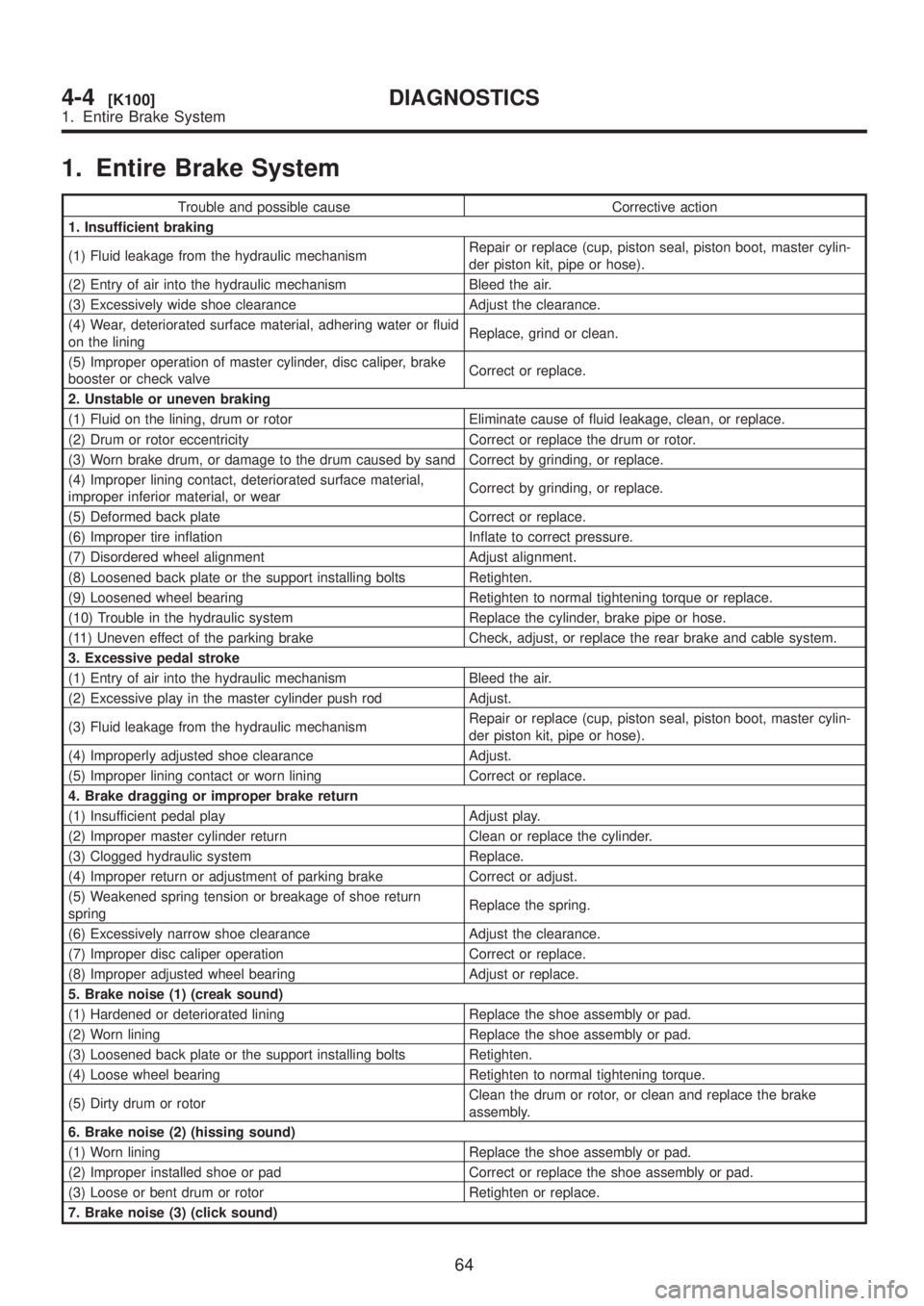
1. Entire Brake System
Trouble and possible cause Corrective action
1. Insufficient braking
(1) Fluid leakage from the hydraulic mechanismRepair or replace (cup, piston seal, piston boot, master cylin-
der piston kit, pipe or hose).
(2) Entry of air into the hydraulic mechanism Bleed the air.
(3) Excessively wide shoe clearance Adjust the clearance.
(4) Wear, deteriorated surface material, adhering water or fluid
on the liningReplace, grind or clean.
(5) Improper operation of master cylinder, disc caliper, brake
booster or check valveCorrect or replace.
2. Unstable or uneven braking
(1) Fluid on the lining, drum or rotor Eliminate cause of fluid leakage, clean, or replace.
(2) Drum or rotor eccentricity Correct or replace the drum or rotor.
(3) Worn brake drum, or damage to the drum caused by sand Correct by grinding, or replace.
(4) Improper lining contact, deteriorated surface material,
improper inferior material, or wearCorrect by grinding, or replace.
(5) Deformed back plate Correct or replace.
(6) Improper tire inflation Inflate to correct pressure.
(7) Disordered wheel alignment Adjust alignment.
(8) Loosened back plate or the support installing bolts Retighten.
(9) Loosened wheel bearing Retighten to normal tightening torque or replace.
(10) Trouble in the hydraulic system Replace the cylinder, brake pipe or hose.
(11) Uneven effect of the parking brake Check, adjust, or replace the rear brake and cable system.
3. Excessive pedal stroke
(1) Entry of air into the hydraulic mechanism Bleed the air.
(2) Excessive play in the master cylinder push rod Adjust.
(3) Fluid leakage from the hydraulic mechanismRepair or replace (cup, piston seal, piston boot, master cylin-
der piston kit, pipe or hose).
(4) Improperly adjusted shoe clearance Adjust.
(5) Improper lining contact or worn lining Correct or replace.
4. Brake dragging or improper brake return
(1) Insufficient pedal play Adjust play.
(2) Improper master cylinder return Clean or replace the cylinder.
(3) Clogged hydraulic system Replace.
(4) Improper return or adjustment of parking brake Correct or adjust.
(5) Weakened spring tension or breakage of shoe return
springReplace the spring.
(6) Excessively narrow shoe clearance Adjust the clearance.
(7) Improper disc caliper operation Correct or replace.
(8) Improper adjusted wheel bearing Adjust or replace.
5. Brake noise (1) (creak sound)
(1) Hardened or deteriorated lining Replace the shoe assembly or pad.
(2) Worn lining Replace the shoe assembly or pad.
(3) Loosened back plate or the support installing bolts Retighten.
(4) Loose wheel bearing Retighten to normal tightening torque.
(5) Dirty drum or rotorClean the drum or rotor, or clean and replace the brake
assembly.
6. Brake noise (2) (hissing sound)
(1) Worn lining Replace the shoe assembly or pad.
(2) Improper installed shoe or pad Correct or replace the shoe assembly or pad.
(3) Loose or bent drum or rotor Retighten or replace.
7. Brake noise (3) (click sound)
64
4-4[K100]DIAGNOSTICS
1. Entire Brake System