transmission SUBARU LEGACY 1999 Service Workshop Manual
[x] Cancel search | Manufacturer: SUBARU, Model Year: 1999, Model line: LEGACY, Model: SUBARU LEGACY 1999Pages: 1456, PDF Size: 59.93 MB
Page 492 of 1456
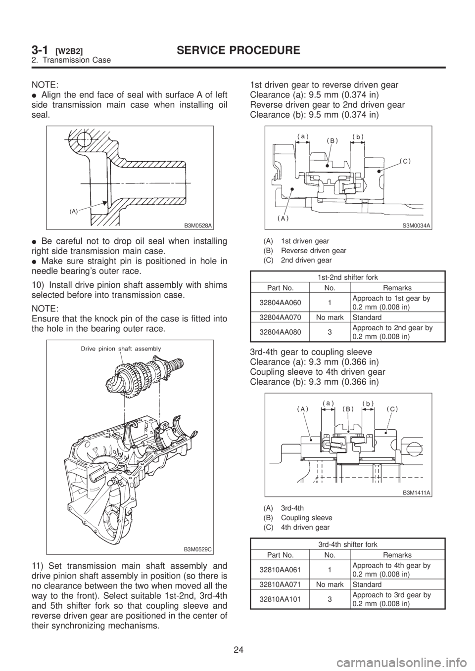
NOTE:
IAlign the end face of seal with surface A of left
side transmission main case when installing oil
seal.
B3M0528A
IBe careful not to drop oil seal when installing
right side transmission main case.
IMake sure straight pin is positioned in hole in
needle bearing's outer race.
10) Install drive pinion shaft assembly with shims
selected before into transmission case.
NOTE:
Ensure that the knock pin of the case is fitted into
the hole in the bearing outer race.
B3M0529C
11) Set transmission main shaft assembly and
drive pinion shaft assembly in position (so there is
no clearance between the two when moved all the
way to the front). Select suitable 1st-2nd, 3rd-4th
and 5th shifter fork so that coupling sleeve and
reverse driven gear are positioned in the center of
their synchronizing mechanisms.1st driven gear to reverse driven gear
Clearance (a): 9.5 mm (0.374 in)
Reverse driven gear to 2nd driven gear
Clearance (b): 9.5 mm (0.374 in)
S3M0034A
(A) 1st driven gear
(B) Reverse driven gear
(C) 2nd driven gear
1st-2nd shifter fork
Part No. No. Remarks
32804AA060 1Approach to 1st gear by
0.2 mm (0.008 in)
32804AA070 No mark Standard
32804AA080 3Approach to 2nd gear by
0.2 mm (0.008 in)
3rd-4th gear to coupling sleeve
Clearance (a): 9.3 mm (0.366 in)
Coupling sleeve to 4th driven gear
Clearance (b): 9.3 mm (0.366 in)
B3M1411A
(A) 3rd-4th
(B) Coupling sleeve
(C) 4th driven gear
3rd-4th shifter fork
Part No. No. Remarks
32810AA061 1Approach to 4th gear by
0.2 mm (0.008 in)
32810AA071 No mark Standard
32810AA101 3Approach to 3rd gear by
0.2 mm (0.008 in)
24
3-1[W2B2]SERVICE PROCEDURE
2. Transmission Case
Page 493 of 1456
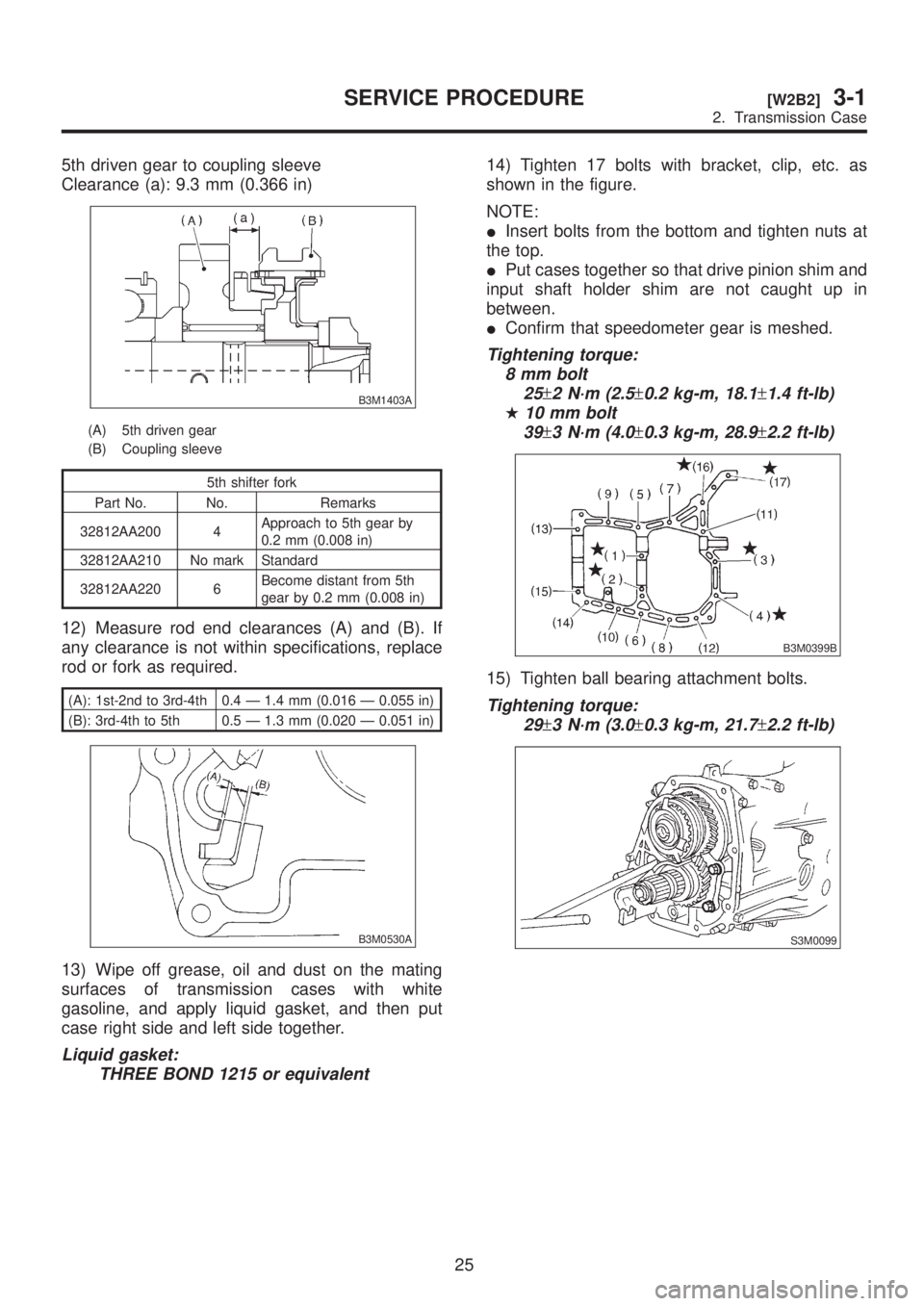
5th driven gear to coupling sleeve
Clearance (a): 9.3 mm (0.366 in)
B3M1403A
(A) 5th driven gear
(B) Coupling sleeve
5th shifter fork
Part No. No. Remarks
32812AA200 4Approach to 5th gear by
0.2 mm (0.008 in)
32812AA210 No mark Standard
32812AA220 6Become distant from 5th
gear by 0.2 mm (0.008 in)
12) Measure rod end clearances (A) and (B). If
any clearance is not within specifications, replace
rod or fork as required.
(A): 1st-2nd to 3rd-4th 0.4 Ð 1.4 mm (0.016 Ð 0.055 in)
(B): 3rd-4th to 5th 0.5 Ð 1.3 mm (0.020 Ð 0.051 in)
B3M0530A
13) Wipe off grease, oil and dust on the mating
surfaces of transmission cases with white
gasoline, and apply liquid gasket, and then put
case right side and left side together.
Liquid gasket:
THREE BOND 1215 or equivalent
14) Tighten 17 bolts with bracket, clip, etc. as
shown in the figure.
NOTE:
IInsert bolts from the bottom and tighten nuts at
the top.
IPut cases together so that drive pinion shim and
input shaft holder shim are not caught up in
between.
IConfirm that speedometer gear is meshed.
Tightening torque:
8 mm bolt
25
±2 N´m (2.5±0.2 kg-m, 18.1±1.4 ft-lb)
H10 mm bolt
39
±3 N´m (4.0±0.3 kg-m, 28.9±2.2 ft-lb)
B3M0399B
15) Tighten ball bearing attachment bolts.
Tightening torque:
29
±3 N´m (3.0±0.3 kg-m, 21.7±2.2 ft-lb)
S3M0099
25
[W2B2]3-1SERVICE PROCEDURE
2. Transmission Case
Page 494 of 1456
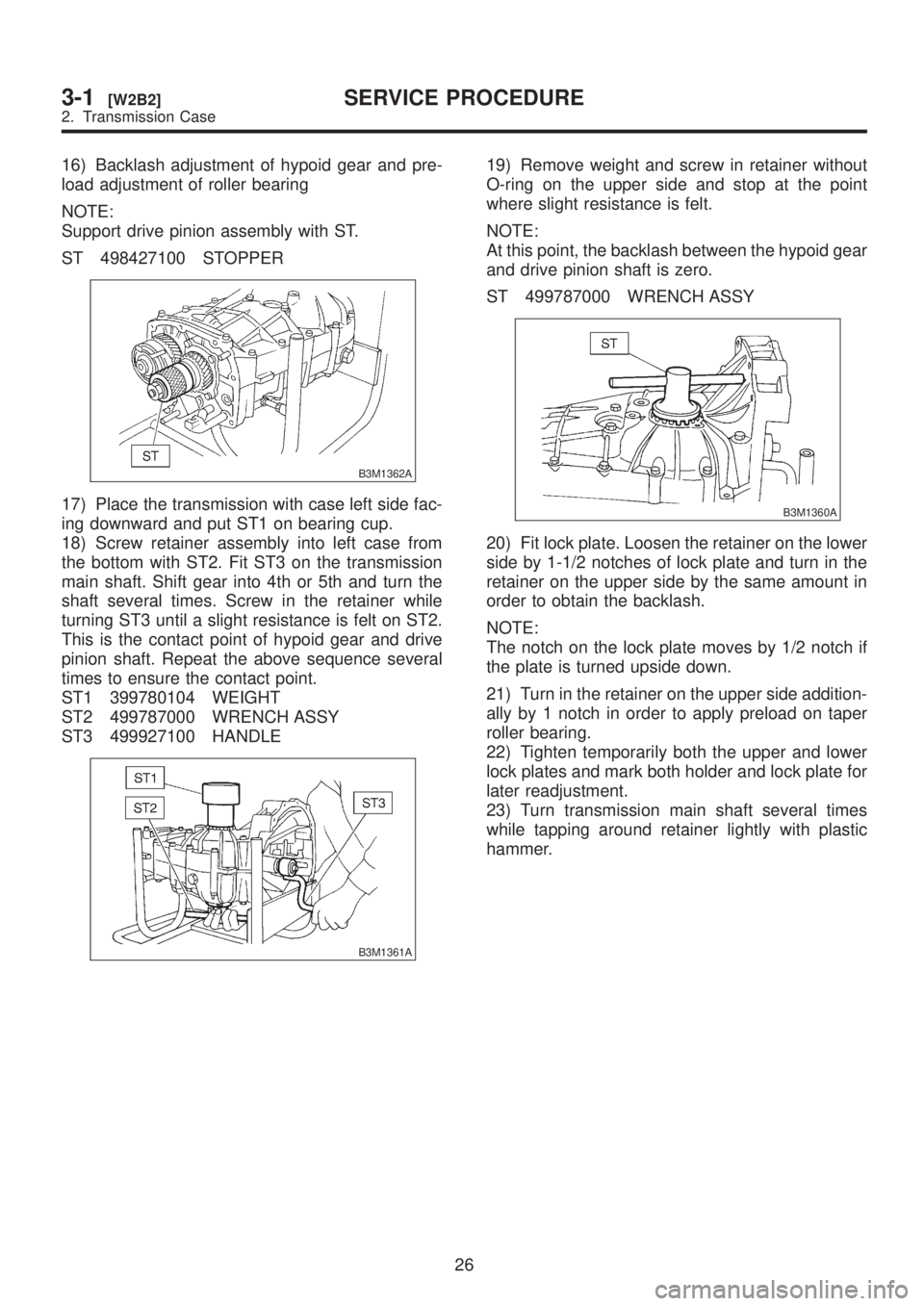
16) Backlash adjustment of hypoid gear and pre-
load adjustment of roller bearing
NOTE:
Support drive pinion assembly with ST.
ST 498427100 STOPPER
B3M1362A
17) Place the transmission with case left side fac-
ing downward and put ST1 on bearing cup.
18) Screw retainer assembly into left case from
the bottom with ST2. Fit ST3 on the transmission
main shaft. Shift gear into 4th or 5th and turn the
shaft several times. Screw in the retainer while
turning ST3 until a slight resistance is felt on ST2.
This is the contact point of hypoid gear and drive
pinion shaft. Repeat the above sequence several
times to ensure the contact point.
ST1 399780104 WEIGHT
ST2 499787000 WRENCH ASSY
ST3 499927100 HANDLE
B3M1361A
19) Remove weight and screw in retainer without
O-ring on the upper side and stop at the point
where slight resistance is felt.
NOTE:
At this point, the backlash between the hypoid gear
and drive pinion shaft is zero.
ST 499787000 WRENCH ASSY
B3M1360A
20) Fit lock plate. Loosen the retainer on the lower
side by 1-1/2 notches of lock plate and turn in the
retainer on the upper side by the same amount in
order to obtain the backlash.
NOTE:
The notch on the lock plate moves by 1/2 notch if
the plate is turned upside down.
21) Turn in the retainer on the upper side addition-
ally by 1 notch in order to apply preload on taper
roller bearing.
22) Tighten temporarily both the upper and lower
lock plates and mark both holder and lock plate for
later readjustment.
23) Turn transmission main shaft several times
while tapping around retainer lightly with plastic
hammer.
26
3-1[W2B2]SERVICE PROCEDURE
2. Transmission Case
Page 495 of 1456
24) Set ST1 and ST2. Insert the needle through
transmission oil drain plug hole so that the needle
comes in contact with the tooth surface at a right
angle and check the backlash.
ST1 498247001 MAGNET BASE
ST2 498247100 DIAL GAUGE
ST3 498255400 PLATE
NOTE:
IIf backlash is outside specified range, adjust it
by turning holder in right side case.
IEach time holder rotates one tooth, backlash
changes by 0.05 mm (0.0020 in).
Backlash:
0.13 Ð 0.18 mm (0.0051 Ð 0.0071 in)
B3M1363A
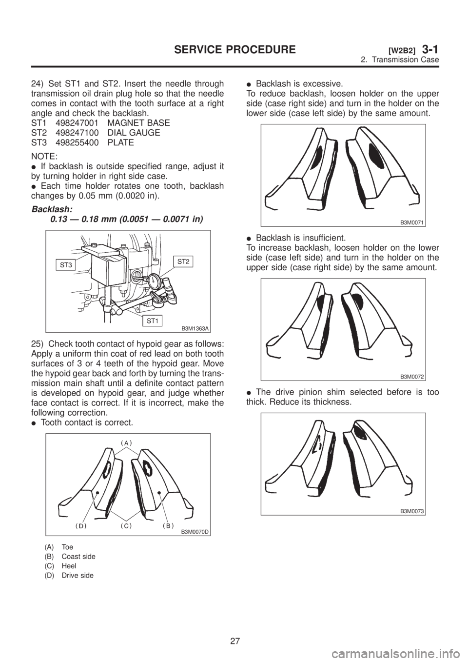
25) Check tooth contact of hypoid gear as follows:
Apply a uniform thin coat of red lead on both tooth
surfaces of 3 or 4 teeth of the hypoid gear. Move
the hypoid gear back and forth by turning the trans-
mission main shaft until a definite contact pattern
is developed on hypoid gear, and judge whether
face contact is correct. If it is incorrect, make the
following correction.
ITooth contact is correct.
B3M0070D
(A) Toe
(B) Coast side
(C) Heel
(D) Drive side
IBacklash is excessive.
To reduce backlash, loosen holder on the upper
side (case right side) and turn in the holder on the
lower side (case left side) by the same amount.
B3M0071
IBacklash is insufficient.
To increase backlash, loosen holder on the lower
side (case left side) and turn in the holder on the
upper side (case right side) by the same amount.
B3M0072
IThe drive pinion shim selected before is too
thick. Reduce its thickness.
B3M0073
27
[W2B2]3-1SERVICE PROCEDURE
2. Transmission Case
Page 496 of 1456
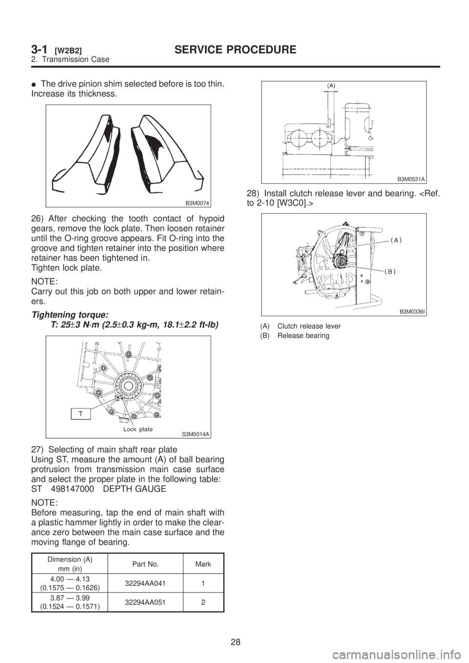
IThe drive pinion shim selected before is too thin.
Increase its thickness.
B3M0074
26) After checking the tooth contact of hypoid
gears, remove the lock plate. Then loosen retainer
until the O-ring groove appears. Fit O-ring into the
groove and tighten retainer into the position where
retainer has been tightened in.
Tighten lock plate.
NOTE:
Carry out this job on both upper and lower retain-
ers.
Tightening torque:
T: 2 5
±3 N´m (2.5±0.3 kg-m, 18.1±2.2 ft-lb)
S3M0014A
27) Selecting of main shaft rear plate
Using ST, measure the amount (A) of ball bearing
protrusion from transmission main case surface
and select the proper plate in the following table:
ST 498147000 DEPTH GAUGE
NOTE:
Before measuring, tap the end of main shaft with
a plastic hammer lightly in order to make the clear-
ance zero between the main case surface and the
moving flange of bearing.
Dimension (A)
mm (in)Part No. Mark
4.00 Ð 4.13
(0.1575 Ð 0.1626)32294AA041 1
3.87 Ð 3.99
(0.1524 Ð 0.1571)32294AA051 2
B3M0531A
28) Install clutch release lever and bearing.
B3M0336I
(A) Clutch release lever
(B) Release bearing
28
3-1[W2B2]SERVICE PROCEDURE
2. Transmission Case
Page 503 of 1456
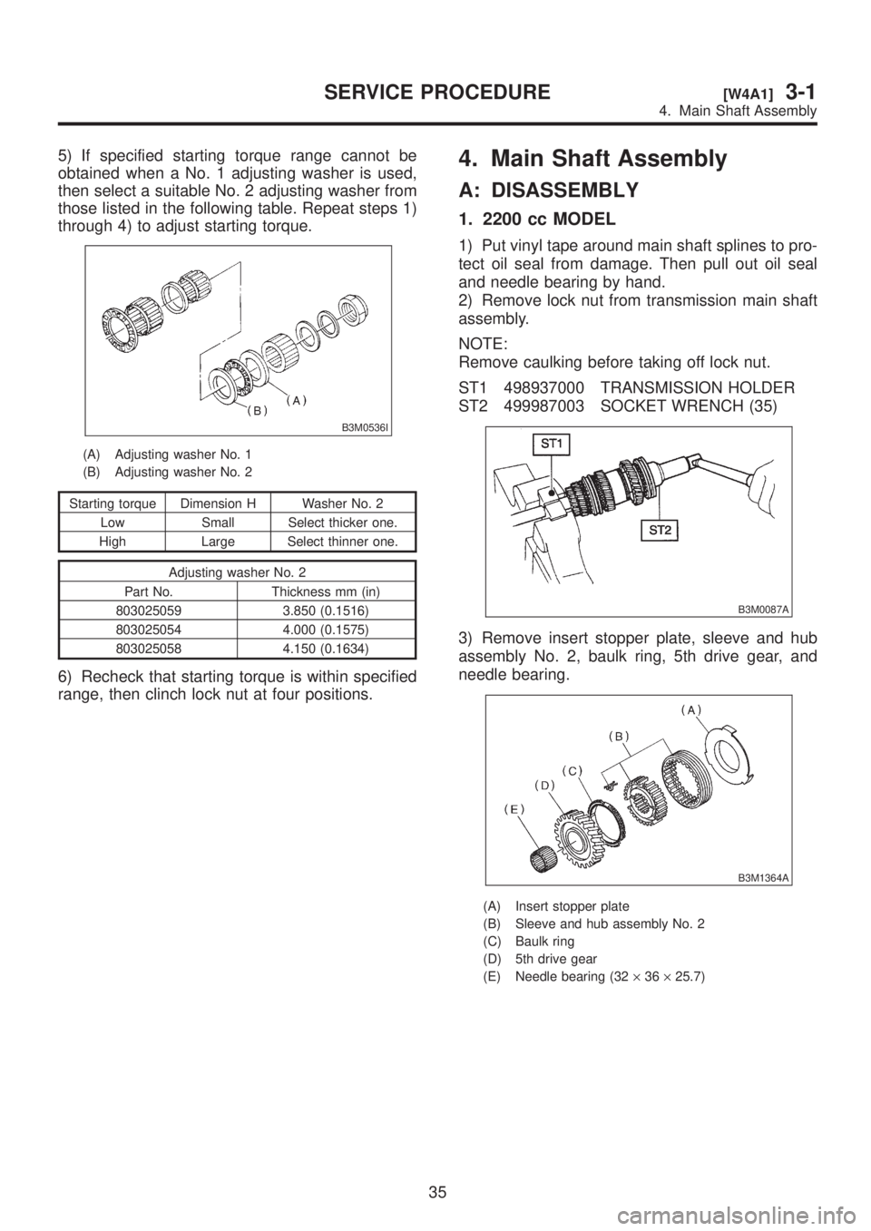
5) If specified starting torque range cannot be
obtained when a No. 1 adjusting washer is used,
then select a suitable No. 2 adjusting washer from
those listed in the following table. Repeat steps 1)
through 4) to adjust starting torque.
B3M0536I
(A) Adjusting washer No. 1
(B) Adjusting washer No. 2
Starting torque Dimension H Washer No. 2
Low Small Select thicker one.
High Large Select thinner one.
Adjusting washer No. 2
Part No. Thickness mm (in)
803025059 3.850 (0.1516)
803025054 4.000 (0.1575)
803025058 4.150 (0.1634)
6) Recheck that starting torque is within specified
range, then clinch lock nut at four positions.
4. Main Shaft Assembly
A: DISASSEMBLY
1. 2200 cc MODEL
1) Put vinyl tape around main shaft splines to pro-
tect oil seal from damage. Then pull out oil seal
and needle bearing by hand.
2) Remove lock nut from transmission main shaft
assembly.
NOTE:
Remove caulking before taking off lock nut.
ST1 498937000 TRANSMISSION HOLDER
ST2 499987003 SOCKET WRENCH (35)
B3M0087A
3) Remove insert stopper plate, sleeve and hub
assembly No. 2, baulk ring, 5th drive gear, and
needle bearing.
B3M1364A
(A) Insert stopper plate
(B) Sleeve and hub assembly No. 2
(C) Baulk ring
(D) 5th drive gear
(E) Needle bearing (32´36´25.7)
35
[W4A1]3-1SERVICE PROCEDURE
4. Main Shaft Assembly
Page 504 of 1456
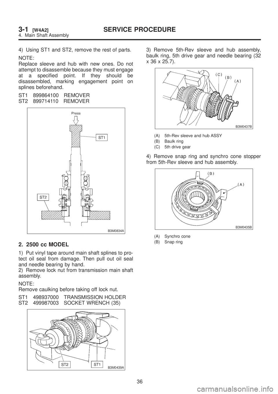
4) Using ST1 and ST2, remove the rest of parts.
NOTE:
Replace sleeve and hub with new ones. Do not
attempt to disassemble because they must engage
at a specified point. If they should be
disassembled, marking engagement point on
splines beforehand.
ST1 899864100 REMOVER
ST2 899714110 REMOVER
B3M0834A
2. 2500 cc MODEL
1) Put vinyl tape around main shaft splines to pro-
tect oil seal from damage. Then pull out oil seal
and needle bearing by hand.
2) Remove lock nut from transmission main shaft
assembly.
NOTE:
Remove caulking before taking off lock nut.
ST1 498937000 TRANSMISSION HOLDER
ST2 499987003 SOCKET WRENCH (35)
B3M0439A
3) Remove 5th-Rev sleeve and hub assembly,
baulk ring, 5th drive gear and needle bearing (32
x 36 x 25.7).
B3M0437B
(A) 5th-Rev sleeve and hub ASSY
(B) Baulk ring
(C) 5th drive gear
4) Remove snap ring and synchro cone stopper
from 5th-Rev sleeve and hub assembly.
B3M0435B
(A) Synchro cone
(B) Snap ring
36
3-1[W4A2]SERVICE PROCEDURE
4. Main Shaft Assembly
Page 506 of 1456
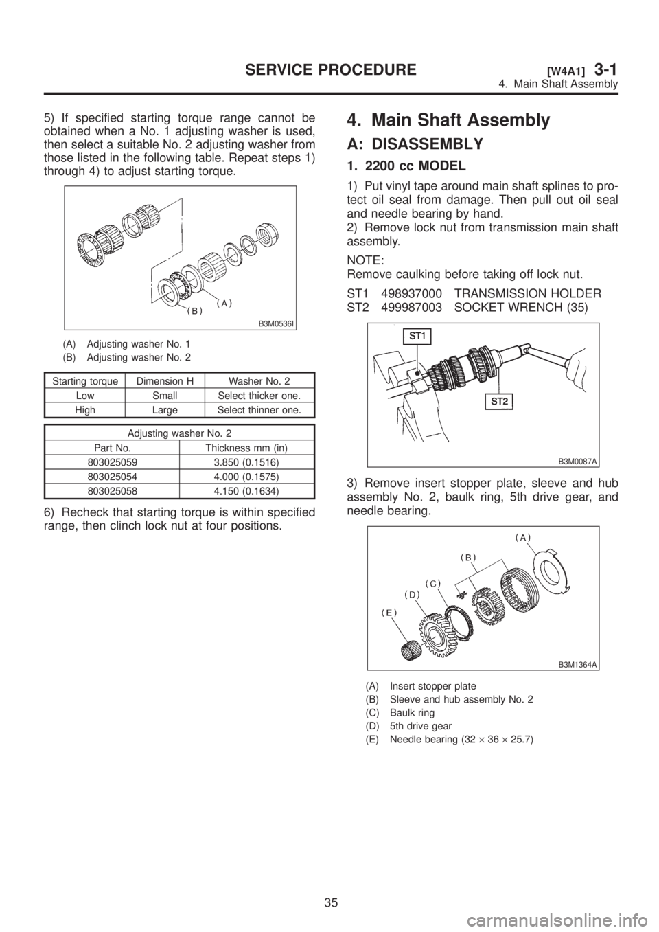
5) If specified starting torque range cannot be
obtained when a No. 1 adjusting washer is used,
then select a suitable No. 2 adjusting washer from
those listed in the following table. Repeat steps 1)
through 4) to adjust starting torque.
B3M0536I
(A) Adjusting washer No. 1
(B) Adjusting washer No. 2
Starting torque Dimension H Washer No. 2
Low Small Select thicker one.
High Large Select thinner one.
Adjusting washer No. 2
Part No. Thickness mm (in)
803025059 3.850 (0.1516)
803025054 4.000 (0.1575)
803025058 4.150 (0.1634)
6) Recheck that starting torque is within specified
range, then clinch lock nut at four positions.
4. Main Shaft Assembly
A: DISASSEMBLY
1. 2200 cc MODEL
1) Put vinyl tape around main shaft splines to pro-
tect oil seal from damage. Then pull out oil seal
and needle bearing by hand.
2) Remove lock nut from transmission main shaft
assembly.
NOTE:
Remove caulking before taking off lock nut.
ST1 498937000 TRANSMISSION HOLDER
ST2 499987003 SOCKET WRENCH (35)
B3M0087A
3) Remove insert stopper plate, sleeve and hub
assembly No. 2, baulk ring, 5th drive gear, and
needle bearing.
B3M1364A
(A) Insert stopper plate
(B) Sleeve and hub assembly No. 2
(C) Baulk ring
(D) 5th drive gear
(E) Needle bearing (32´36´25.7)
35
[W4A1]3-1SERVICE PROCEDURE
4. Main Shaft Assembly
Page 507 of 1456
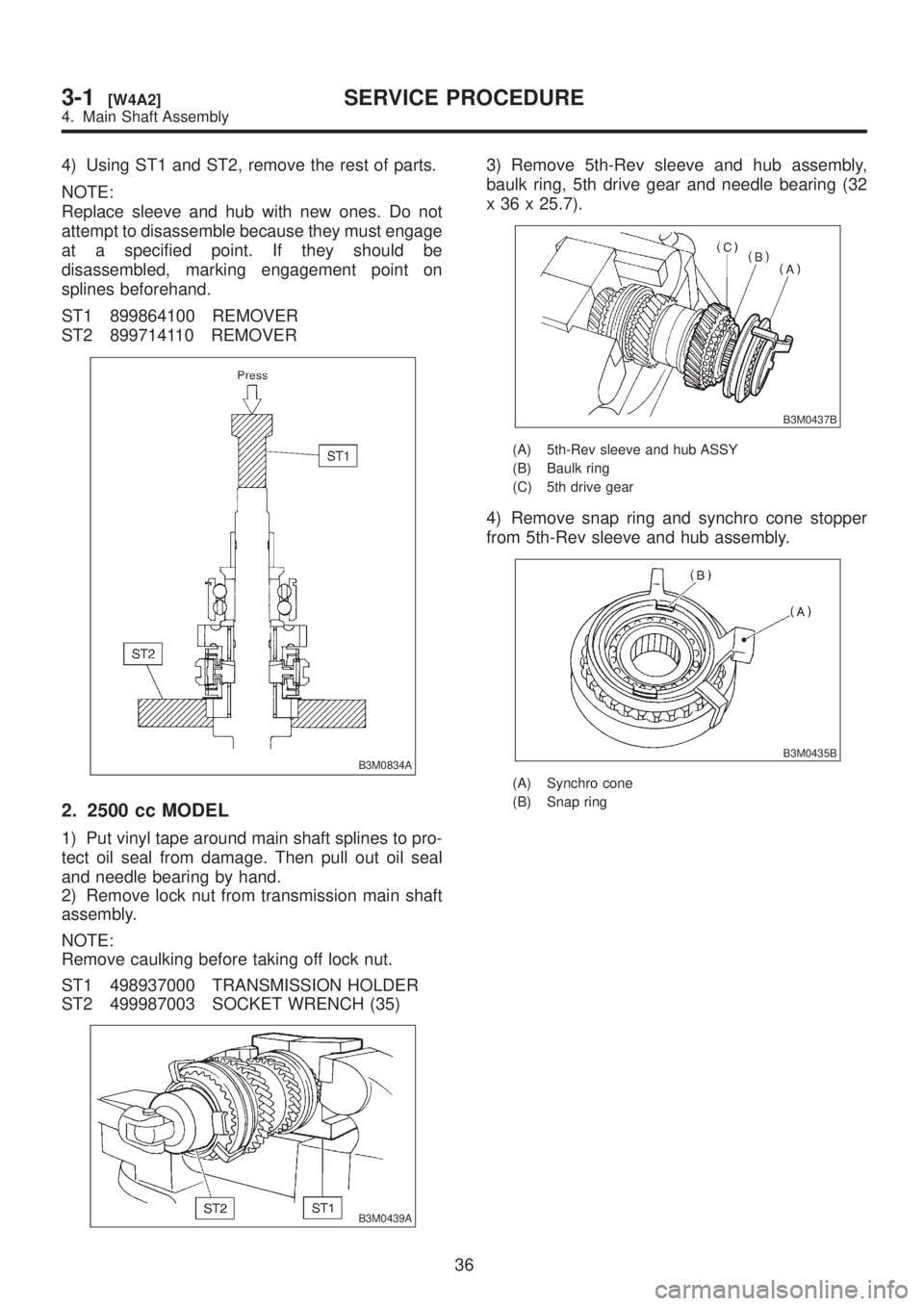
4) Using ST1 and ST2, remove the rest of parts.
NOTE:
Replace sleeve and hub with new ones. Do not
attempt to disassemble because they must engage
at a specified point. If they should be
disassembled, marking engagement point on
splines beforehand.
ST1 899864100 REMOVER
ST2 899714110 REMOVER
B3M0834A
2. 2500 cc MODEL
1) Put vinyl tape around main shaft splines to pro-
tect oil seal from damage. Then pull out oil seal
and needle bearing by hand.
2) Remove lock nut from transmission main shaft
assembly.
NOTE:
Remove caulking before taking off lock nut.
ST1 498937000 TRANSMISSION HOLDER
ST2 499987003 SOCKET WRENCH (35)
B3M0439A
3) Remove 5th-Rev sleeve and hub assembly,
baulk ring, 5th drive gear and needle bearing (32
x 36 x 25.7).
B3M0437B
(A) 5th-Rev sleeve and hub ASSY
(B) Baulk ring
(C) 5th drive gear
4) Remove snap ring and synchro cone stopper
from 5th-Rev sleeve and hub assembly.
B3M0435B
(A) Synchro cone
(B) Snap ring
36
3-1[W4A2]SERVICE PROCEDURE
4. Main Shaft Assembly
Page 509 of 1456
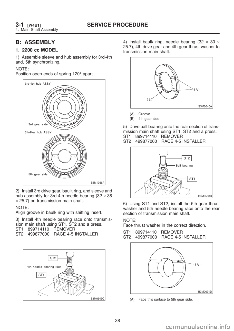
B: ASSEMBLY
1. 2200 cc MODEL
1) Assemble sleeve and hub assembly for 3rd-4th
and, 5th synchronizing.
NOTE:
Position open ends of spring 120É apart.
B3M1366A
2) Install 3rd drive gear, baulk ring, and sleeve and
hub assembly for 3rd-4th needle bearing (32´36
´25.7) on transmission main shaft.
NOTE:
Align groove in baulk ring with shifting insert.
3) Install 4th needle bearing race onto transmis-
sion main shaft using ST1, ST2 and a press.
ST1 899714110 REMOVER
ST2 499877000 RACE 4-5 INSTALLER
B3M0543C
4) Install baulk ring, needle bearing (32´30´
25.7), 4th drive gear and 4th gear thrust washer to
transmission main shaft.
S3M0045A
(A) Groove
(B) 4th gear side
5) Drive ball bearing onto the rear section of trans-
mission main shaft using ST1, ST2 and a press.
ST1 899714110 REMOVER
ST2 499877000 RACE 4-5 INSTALLER
B3M0553D
6) Using ST1 and ST2, install the 5th gear thrust
washer and 5th needle bearing race onto the rear
section of transmission main shaft.
NOTE:
Face thrust washer in the correct direction.
ST1 899714110 REMOVER
ST2 499877000 RACE 4-5 INSTALLER
B3M0091D
(A) Face this surface to 5th gear side.
38
3-1[W4B1]SERVICE PROCEDURE
4. Main Shaft Assembly