air compressor SUBARU LEGACY 1999 Service Repair Manual
[x] Cancel search | Manufacturer: SUBARU, Model Year: 1999, Model line: LEGACY, Model: SUBARU LEGACY 1999Pages: 1456, PDF Size: 59.93 MB
Page 35 of 1456
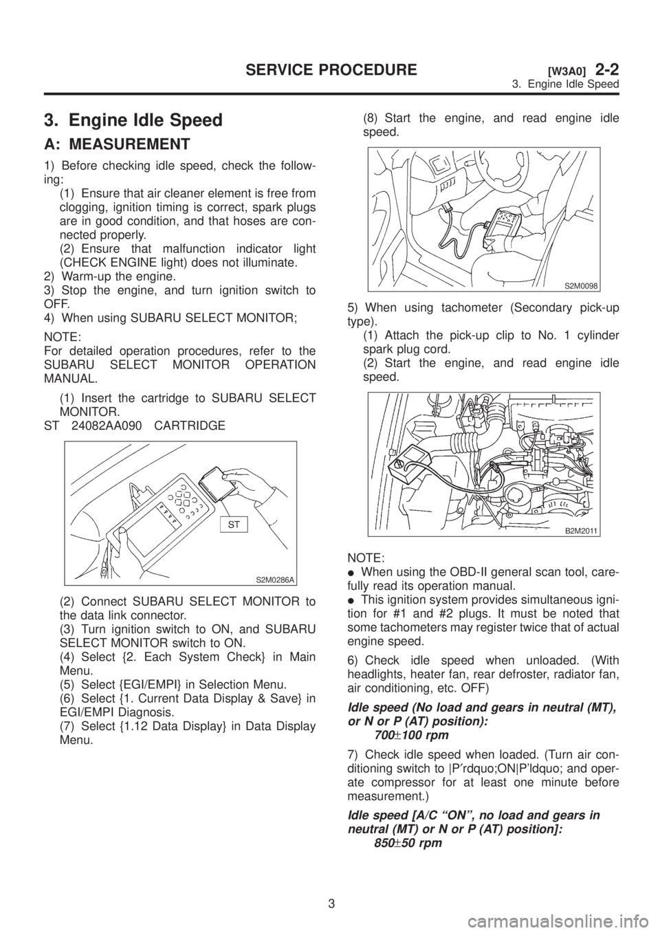
3. Engine Idle Speed
A: MEASUREMENT
1) Before checking idle speed, check the follow-
ing:
(1) Ensure that air cleaner element is free from
clogging, ignition timing is correct, spark plugs
are in good condition, and that hoses are con-
nected properly.
(2) Ensure that malfunction indicator light
(CHECK ENGINE light) does not illuminate.
2) Warm-up the engine.
3) Stop the engine, and turn ignition switch to
OFF.
4) When using SUBARU SELECT MONITOR;
NOTE:
For detailed operation procedures, refer to the
SUBARU SELECT MONITOR OPERATION
MANUAL.
(1) Insert the cartridge to SUBARU SELECT
MONITOR.
ST 24082AA090 CARTRIDGE
S2M0286A
(2) Connect SUBARU SELECT MONITOR to
the data link connector.
(3) Turn ignition switch to ON, and SUBARU
SELECT MONITOR switch to ON.
(4) Select {2. Each System Check} in Main
Menu.
(5) Select {EGI/EMPI} in Selection Menu.
(6) Select {1. Current Data Display & Save} in
EGI/EMPI Diagnosis.
(7) Select {1.12 Data Display} in Data Display
Menu.(8) Start the engine, and read engine idle
speed.
S2M0098
5) When using tachometer (Secondary pick-up
type).
(1) Attach the pick-up clip to No. 1 cylinder
spark plug cord.
(2) Start the engine, and read engine idle
speed.
B2M2011
NOTE:
IWhen using the OBD-II general scan tool, care-
fully read its operation manual.
IThis ignition system provides simultaneous igni-
tion for #1 and #2 plugs. It must be noted that
some tachometers may register twice that of actual
engine speed.
6) Check idle speed when unloaded. (With
headlights, heater fan, rear defroster, radiator fan,
air conditioning, etc. OFF)
Idle speed (No load and gears in neutral (MT),
or N or P (AT) position):
700
±100 rpm
7) Check idle speed when loaded. (Turn air con-
ditioning switch to |P¢rdquo;ON|P'ldquo; and oper-
ate compressor for at least one minute before
measurement.)
Idle speed [A/C ªONº, no load and gears in
neutral (MT) or N or P (AT) position]:
850
±50 rpm
3
[W3A0]2-2SERVICE PROCEDURE
3. Engine Idle Speed
Page 145 of 1456
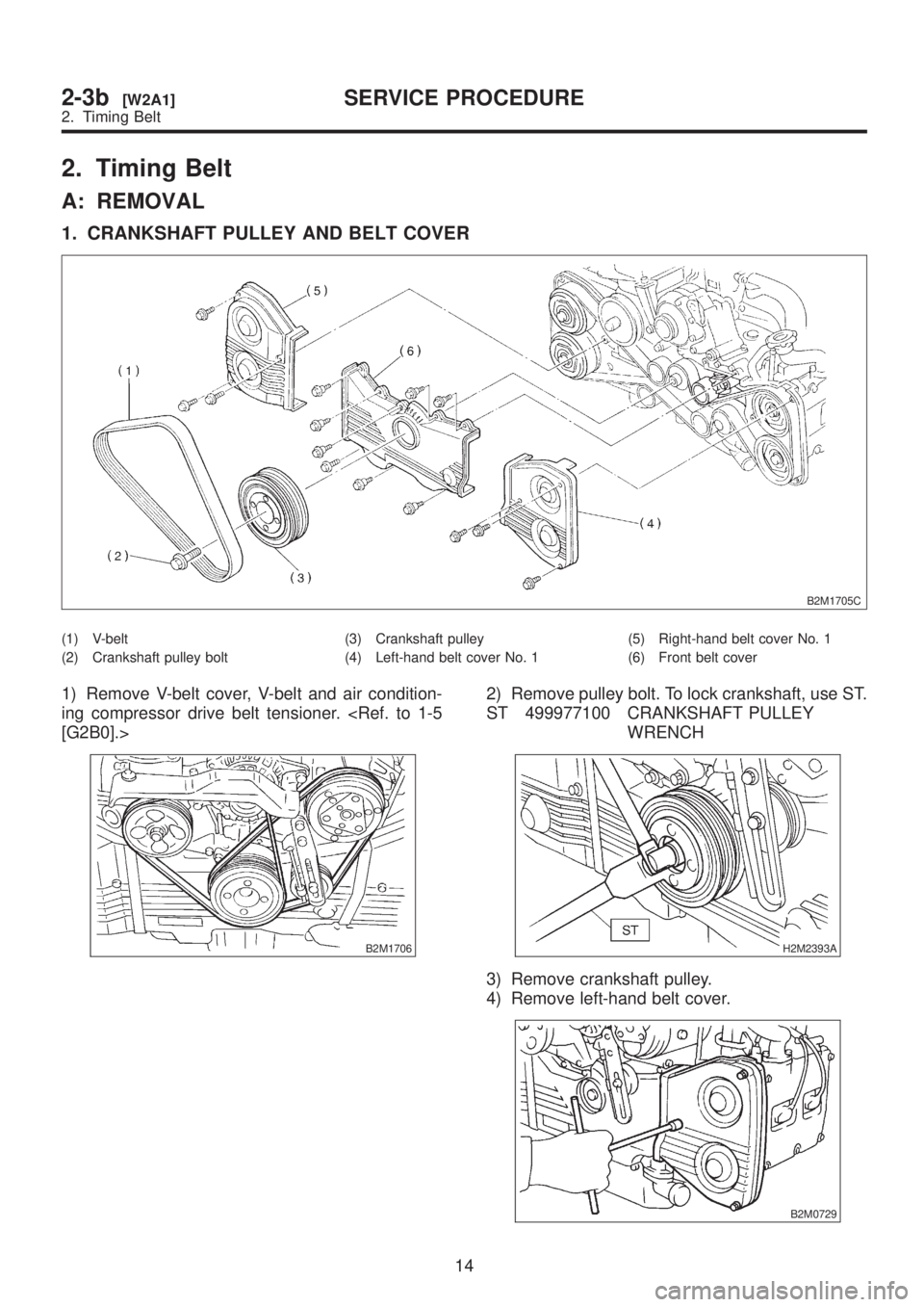
2. Timing Belt
A: REMOVAL
1. CRANKSHAFT PULLEY AND BELT COVER
B2M1705C
(1) V-belt
(2) Crankshaft pulley bolt(3) Crankshaft pulley
(4) Left-hand belt cover No. 1(5) Right-hand belt cover No. 1
(6) Front belt cover
1) Remove V-belt cover, V-belt and air condition-
ing compressor drive belt tensioner.
B2M1706
2) Remove pulley bolt. To lock crankshaft, use ST.
ST 499977100 CRANKSHAFT PULLEY
WRENCH
H2M2393A
3) Remove crankshaft pulley.
4) Remove left-hand belt cover.
B2M0729
14
2-3b[W2A1]SERVICE PROCEDURE
2. Timing Belt
Page 160 of 1456
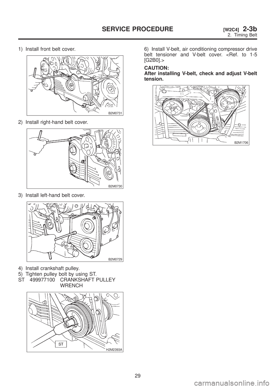
1) Install front belt cover.
B2M0731
2) Install right-hand belt cover.
B2M0730
3) Install left-hand belt cover.
B2M0729
4) Install crankshaft pulley.
5) Tighten pulley bolt by using ST.
ST 499977100 CRANKSHAFT PULLEY
WRENCH
H2M2393A
6) Install V-belt, air conditioning compressor drive
belt tensioner and V-belt cover.
CAUTION:
After installing V-belt, check and adjust V-belt
tension.
B2M1706
29
[W2C4]2-3bSERVICE PROCEDURE
2. Timing Belt
Page 167 of 1456
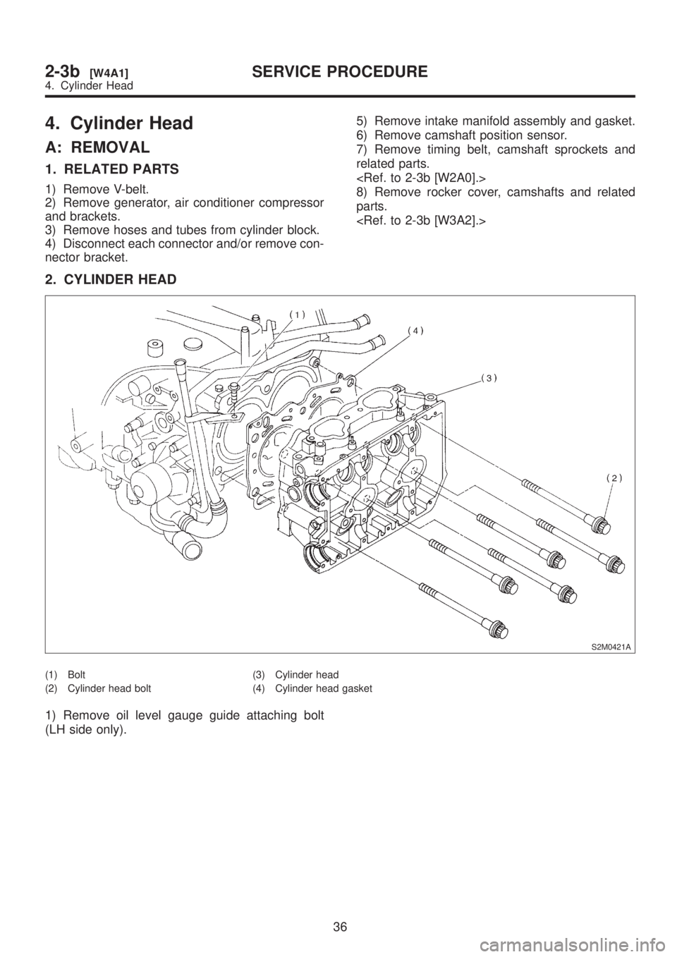
4. Cylinder Head
A: REMOVAL
1. RELATED PARTS
1) Remove V-belt.
2) Remove generator, air conditioner compressor
and brackets.
3) Remove hoses and tubes from cylinder block.
4) Disconnect each connector and/or remove con-
nector bracket.5) Remove intake manifold assembly and gasket.
6) Remove camshaft position sensor.
7) Remove timing belt, camshaft sprockets and
related parts.
8) Remove rocker cover, camshafts and related
parts.
2. CYLINDER HEAD
S2M0421A
(1) Bolt
(2) Cylinder head bolt(3) Cylinder head
(4) Cylinder head gasket
1) Remove oil level gauge guide attaching bolt
(LH side only).
36
2-3b[W4A1]SERVICE PROCEDURE
4. Cylinder Head
Page 178 of 1456
![SUBARU LEGACY 1999 Service Repair Manual 3) Install camshaft sprockets, timing belt and related parts.
<Ref. to 2-3b [W2C1].>
S2M0303
4) Install intake manifold.
CAUTION:
Use new gaskets.
G2M0774
5) Install camshaft position sensor. Use dry SUBARU LEGACY 1999 Service Repair Manual 3) Install camshaft sprockets, timing belt and related parts.
<Ref. to 2-3b [W2C1].>
S2M0303
4) Install intake manifold.
CAUTION:
Use new gaskets.
G2M0774
5) Install camshaft position sensor. Use dry](/img/17/57435/w960_57435-177.png)
3) Install camshaft sprockets, timing belt and related parts.
S2M0303
4) Install intake manifold.
CAUTION:
Use new gaskets.
G2M0774
5) Install camshaft position sensor. Use dry com-
pressed air to remove foreign particles before
installing sensor.
6) Connect each connector and/or install connec-
tor bracket.
7) Connect hoses and tubes to cylinder block.
8) Install brackets, generator and air conditioner
compressor.
9) Install V-belt.
47
[W4E2]2-3bSERVICE PROCEDURE
4. Cylinder Head
Page 440 of 1456
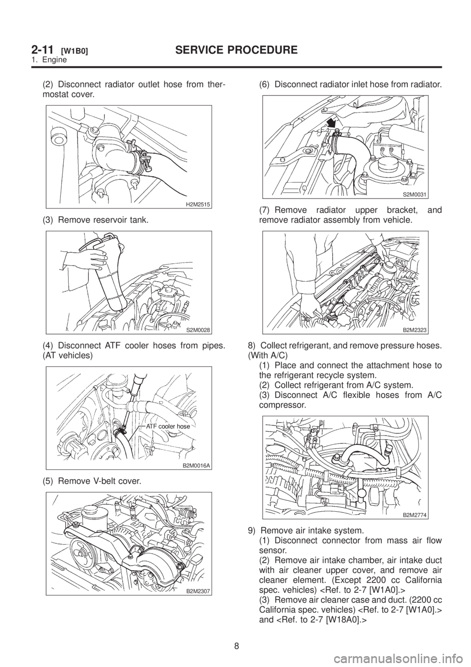
(2) Disconnect radiator outlet hose from ther-
mostat cover.
H2M2515
(3) Remove reservoir tank.
S2M0028
(4) Disconnect ATF cooler hoses from pipes.
(AT vehicles)
B2M0016A
(5) Remove V-belt cover.
B2M2307
(6) Disconnect radiator inlet hose from radiator.
S2M0031
(7) Remove radiator upper bracket, and
remove radiator assembly from vehicle.
B2M2323
8) Collect refrigerant, and remove pressure hoses.
(With A/C)
(1) Place and connect the attachment hose to
the refrigerant recycle system.
(2) Collect refrigerant from A/C system.
(3) Disconnect A/C flexible hoses from A/C
compressor.
B2M2774
9) Remove air intake system.
(1) Disconnect connector from mass air flow
sensor.
(2) Remove air intake chamber, air intake duct
with air cleaner upper cover, and remove air
cleaner element. (Except 2200 cc California
spec. vehicles)
(3) Remove air cleaner case and duct. (2200 cc
California spec. vehicles)
and
8
2-11[W1B0]SERVICE PROCEDURE
1. Engine
Page 607 of 1456
B: DISASSEMBLY
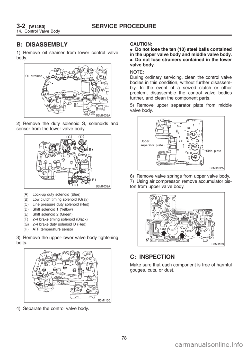
1) Remove oil strainer from lower control valve
body.
B3M1038A
2) Remove the duty solenoid S, solenoids and
sensor from the lower valve body.
B3M1039A
(A) Lock-up duty solenoid (Blue)
(B) Low clutch timing solenoid (Gray)
(C) Line pressure duty solenoid (Red)
(D) Shift solenoid 1 (Yellow)
(E) Shift solenoid 2 (Green)
(F) 2-4 brake timing solenoid (Black)
(G) 2-4 brake duty solenoid D (Red)
(H) ATF temperature sensor
3) Remove the upper-lower valve body tightening
bolts.
B3M1130
4) Separate the control valve body.CAUTION:
IDo not lose the ten (10) steel balls contained
in the upper valve body and middle valve body.
IDo not lose strainers contained in the lower
valve body.
NOTE:
During ordinary servicing, clean the control valve
bodies in this condition, without further disassem-
bly. In the event of a seized clutch or other
problem, disassemble the control valve bodies
further, and clean the component parts.
5) Remove upper separator plate from middle
valve body.
B3M1132A
6) Remove valve springs from upper valve body.
7) Using air compressor, remove accumulator pis-
ton from upper valve body.
B3M1133
C: INSPECTION
Make sure that each component is free of harmful
gouges, cuts, or dust.
78
3-2[W14B0]SERVICE PROCEDURE
14. Control Valve Body
Page 626 of 1456
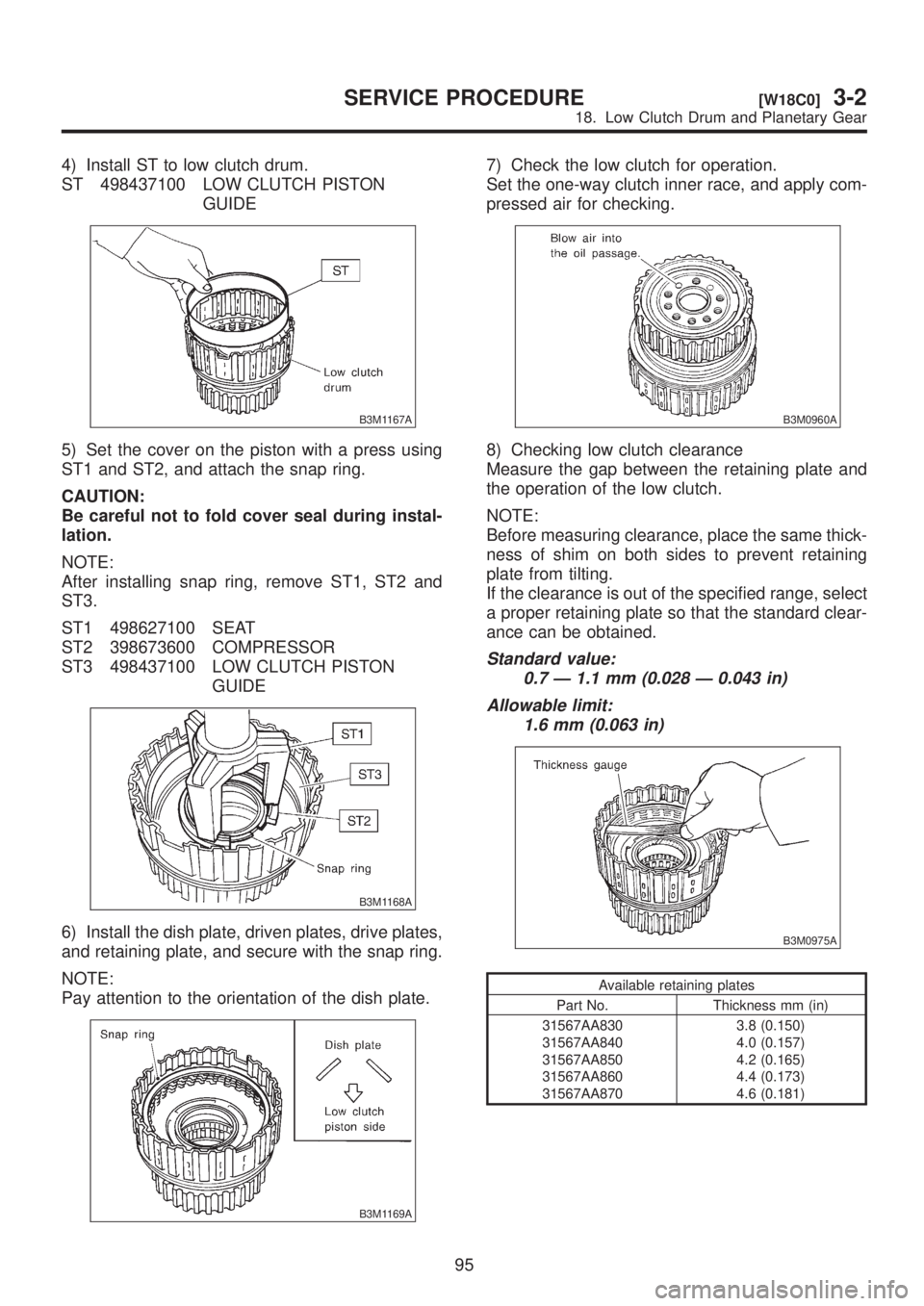
4) Install ST to low clutch drum.
ST 498437100 LOW CLUTCH PISTON
GUIDE
B3M1167A
5) Set the cover on the piston with a press using
ST1 and ST2, and attach the snap ring.
CAUTION:
Be careful not to fold cover seal during instal-
lation.
NOTE:
After installing snap ring, remove ST1, ST2 and
ST3.
ST1 498627100 SEAT
ST2 398673600 COMPRESSOR
ST3 498437100 LOW CLUTCH PISTON
GUIDE
B3M1168A
6) Install the dish plate, driven plates, drive plates,
and retaining plate, and secure with the snap ring.
NOTE:
Pay attention to the orientation of the dish plate.
B3M1169A
7) Check the low clutch for operation.
Set the one-way clutch inner race, and apply com-
pressed air for checking.
B3M0960A
8) Checking low clutch clearance
Measure the gap between the retaining plate and
the operation of the low clutch.
NOTE:
Before measuring clearance, place the same thick-
ness of shim on both sides to prevent retaining
plate from tilting.
If the clearance is out of the specified range, select
a proper retaining plate so that the standard clear-
ance can be obtained.
Standard value:
0.7 Ð 1.1 mm (0.028 Ð 0.043 in)
Allowable limit:
1.6 mm (0.063 in)
B3M0975A
Available retaining plates
Part No. Thickness mm (in)
31567AA830
31567AA840
31567AA850
31567AA860
31567AA8703.8 (0.150)
4.0 (0.157)
4.2 (0.165)
4.4 (0.173)
4.6 (0.181)
95
[W18C0]3-2SERVICE PROCEDURE
18. Low Clutch Drum and Planetary Gear
Page 632 of 1456
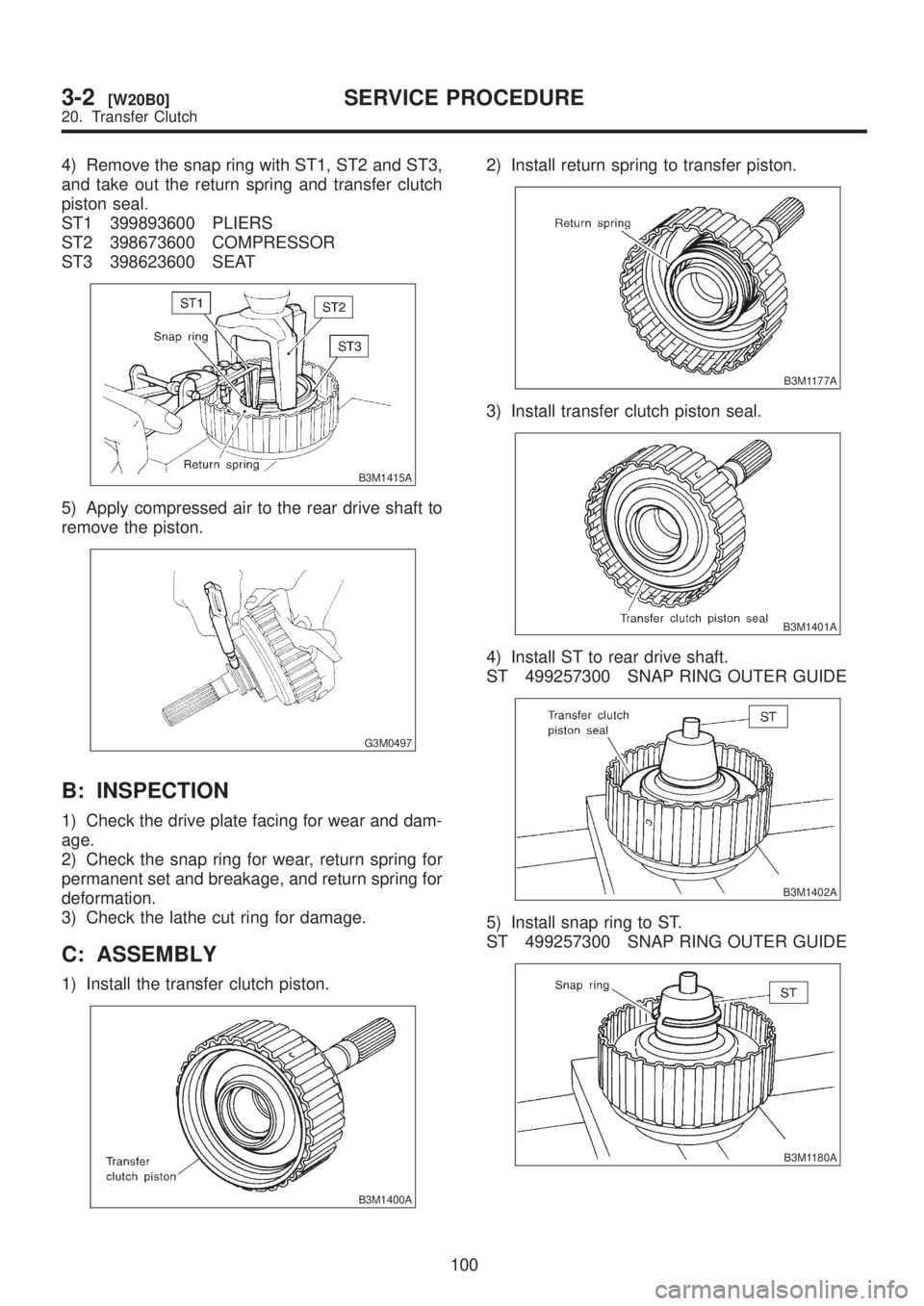
4) Remove the snap ring with ST1, ST2 and ST3,
and take out the return spring and transfer clutch
piston seal.
ST1 399893600 PLIERS
ST2 398673600 COMPRESSOR
ST3 398623600 SEAT
B3M1415A
5) Apply compressed air to the rear drive shaft to
remove the piston.
G3M0497
B: INSPECTION
1) Check the drive plate facing for wear and dam-
age.
2) Check the snap ring for wear, return spring for
permanent set and breakage, and return spring for
deformation.
3) Check the lathe cut ring for damage.
C: ASSEMBLY
1) Install the transfer clutch piston.
B3M1400A
2) Install return spring to transfer piston.
B3M1177A
3) Install transfer clutch piston seal.
B3M1401A
4) Install ST to rear drive shaft.
ST 499257300 SNAP RING OUTER GUIDE
B3M1402A
5) Install snap ring to ST.
ST 499257300 SNAP RING OUTER GUIDE
B3M1180A
100
3-2[W20B0]SERVICE PROCEDURE
20. Transfer Clutch
Page 723 of 1456
2. STRUT MOUNT
Check rubber part for wear, cracks and
deterioration, and replace it with new one if defec-
tive.
3. DUST COVER
If any cracks or damage are found, replace it with
new one.
4. COIL SPRING
When vehicle posture is uneven, although there
are no considerable reasons like tire puncture,
uneven loading, etc., check coil spring and spring
seats for cracks, deformation, etc., and replace it
with a new one if defective.
5. HELPER
Replace it with new one if cracked or damaged.
D: ASSEMBLY
1) Before installing coil spring, strut mount, etc.,
on the strut, check for the presence of air in the
dampening force generating mechanism of the
strut since air prevents proper dampening force
from being produced.
2) Checking for the presence of air
(1) Place the strut vertically with the piston rod
facing upward.
(2) Move the piston rod to the center of its
entire stroke.
(3) While holding the piston rod end with finger-
tips, move the rod up and down.
(4) If the piston rod moves at least 10 mm (0.39
in) in former step, purge air from the strut.
3) Air purging procedure
(1) Place the strut vertically with the piston rod
facing upward.
(2) Fully extend the piston rod.
(3) With the piston rod fully extended, place the
piston rod side down. The strut must stand ver-
tically.
(4) Fully contract the piston rod.
(5) Repeat 3 or 4 times from first step.
NOTE:
After completely purging air from the strut, be sure
to place the strut with the piston rod facing upward.
If it is laid down, check for entry of air in the strut
as outlined under ªChecking for the presence of
airº.4) Using a coil spring compressor, compress the
coil spring.
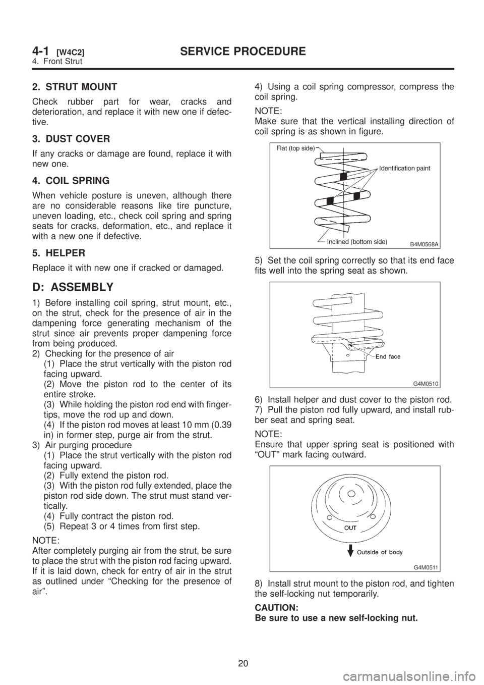
NOTE:
Make sure that the vertical installing direction of
coil spring is as shown in figure.
B4M0568A
5) Set the coil spring correctly so that its end face
fits well into the spring seat as shown.
G4M0510
6) Install helper and dust cover to the piston rod.
7) Pull the piston rod fully upward, and install rub-
ber seat and spring seat.
NOTE:
Ensure that upper spring seat is positioned with
ªOUTº mark facing outward.
G4M0511
8) Install strut mount to the piston rod, and tighten
the self-locking nut temporarily.
CAUTION:
Be sure to use a new self-locking nut.
20
4-1[W4C2]SERVICE PROCEDURE
4. Front Strut