rear brakes SUBARU LEGACY 1999 Service Repair Manual
[x] Cancel search | Manufacturer: SUBARU, Model Year: 1999, Model line: LEGACY, Model: SUBARU LEGACY 1999Pages: 1456, PDF Size: 59.93 MB
Page 415 of 1456
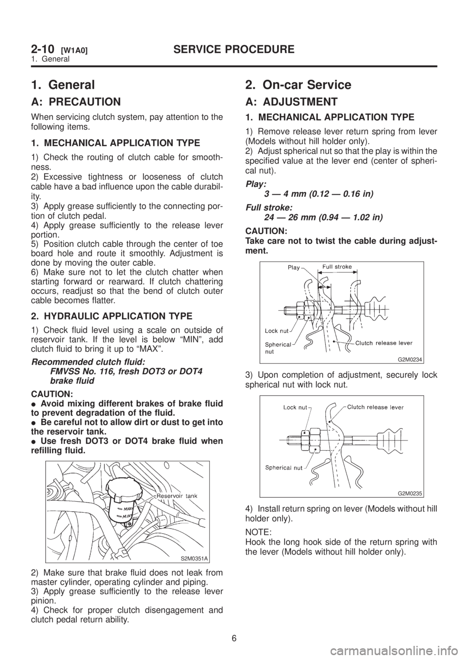
1. General
A: PRECAUTION
When servicing clutch system, pay attention to the
following items.
1. MECHANICAL APPLICATION TYPE
1) Check the routing of clutch cable for smooth-
ness.
2) Excessive tightness or looseness of clutch
cable have a bad influence upon the cable durabil-
ity.
3) Apply grease sufficiently to the connecting por-
tion of clutch pedal.
4) Apply grease sufficiently to the release lever
portion.
5) Position clutch cable through the center of toe
board hole and route it smoothly. Adjustment is
done by moving the outer cable.
6) Make sure not to let the clutch chatter when
starting forward or rearward. If clutch chattering
occurs, readjust so that the bend of clutch outer
cable becomes flatter.
2. HYDRAULIC APPLICATION TYPE
1) Check fluid level using a scale on outside of
reservoir tank. If the level is below ªMINº, add
clutch fluid to bring it up to ªMAXº.
Recommended clutch fluid:
FMVSS No. 116, fresh DOT3 or DOT4
brake fluid
CAUTION:
IAvoid mixing different brakes of brake fluid
to prevent degradation of the fluid.
IBe careful not to allow dirt or dust to get into
the reservoir tank.
IUse fresh DOT3 or DOT4 brake fluid when
refilling fluid.
S2M0351A
2) Make sure that brake fluid does not leak from
master cylinder, operating cylinder and piping.
3) Apply grease sufficiently to the release lever
pinion.
4) Check for proper clutch disengagement and
clutch pedal return ability.
2. On-car Service
A: ADJUSTMENT
1. MECHANICAL APPLICATION TYPE
1) Remove release lever return spring from lever
(Models without hill holder only).
2) Adjust spherical nut so that the play is within the
specified value at the lever end (center of spheri-
cal nut).
Play:
3Ð4mm(0.12 Ð 0.16 in)
Full stroke:
24 Ð 26 mm (0.94 Ð 1.02 in)
CAUTION:
Take care not to twist the cable during adjust-
ment.
G2M0234
3) Upon completion of adjustment, securely lock
spherical nut with lock nut.
G2M0235
4) Install return spring on lever (Models without hill
holder only).
NOTE:
Hook the long hook side of the return spring with
the lever (Models without hill holder only).
6
2-10[W1A0]SERVICE PROCEDURE
1. General
Page 416 of 1456
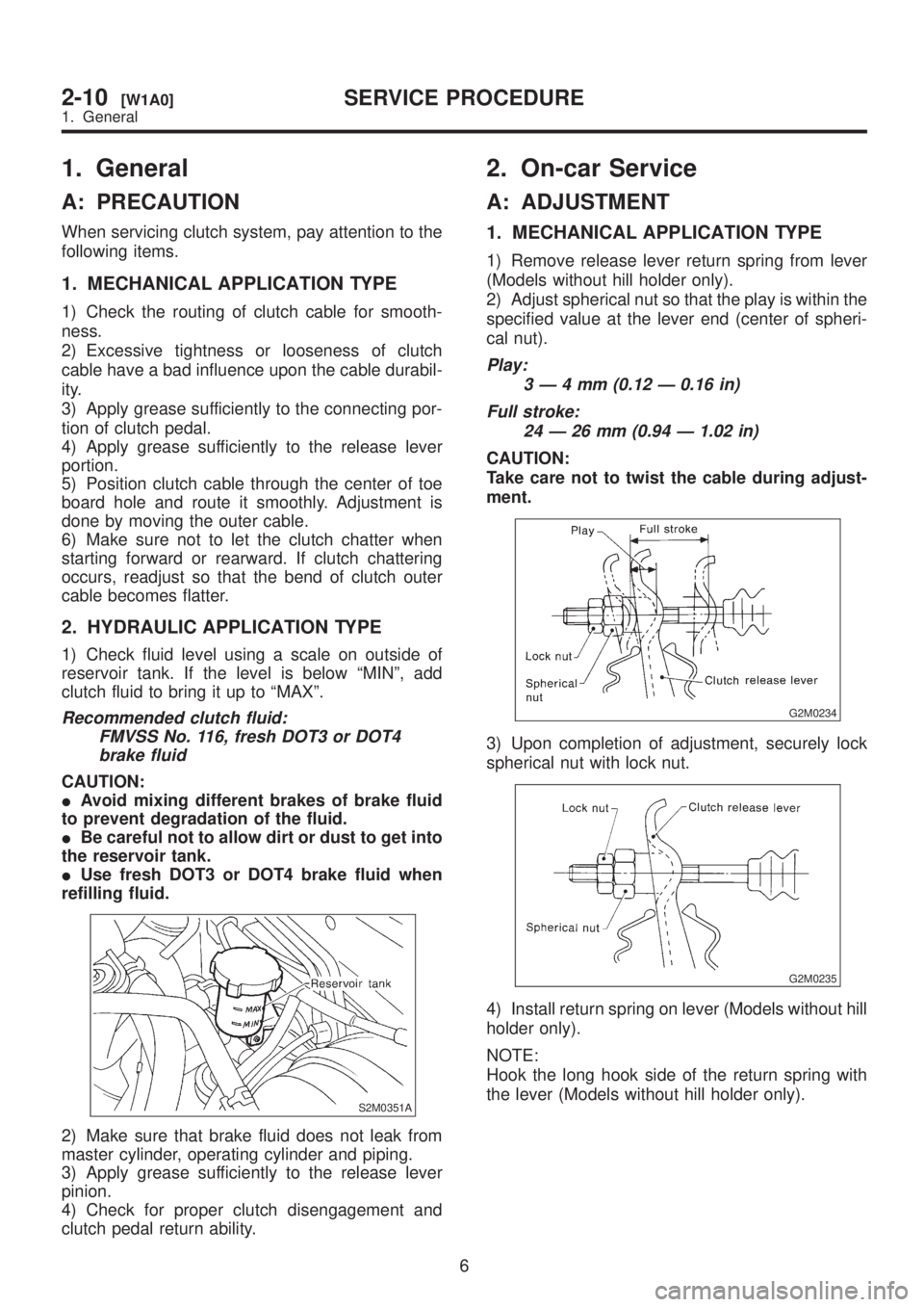
1. General
A: PRECAUTION
When servicing clutch system, pay attention to the
following items.
1. MECHANICAL APPLICATION TYPE
1) Check the routing of clutch cable for smooth-
ness.
2) Excessive tightness or looseness of clutch
cable have a bad influence upon the cable durabil-
ity.
3) Apply grease sufficiently to the connecting por-
tion of clutch pedal.
4) Apply grease sufficiently to the release lever
portion.
5) Position clutch cable through the center of toe
board hole and route it smoothly. Adjustment is
done by moving the outer cable.
6) Make sure not to let the clutch chatter when
starting forward or rearward. If clutch chattering
occurs, readjust so that the bend of clutch outer
cable becomes flatter.
2. HYDRAULIC APPLICATION TYPE
1) Check fluid level using a scale on outside of
reservoir tank. If the level is below ªMINº, add
clutch fluid to bring it up to ªMAXº.
Recommended clutch fluid:
FMVSS No. 116, fresh DOT3 or DOT4
brake fluid
CAUTION:
IAvoid mixing different brakes of brake fluid
to prevent degradation of the fluid.
IBe careful not to allow dirt or dust to get into
the reservoir tank.
IUse fresh DOT3 or DOT4 brake fluid when
refilling fluid.
S2M0351A
2) Make sure that brake fluid does not leak from
master cylinder, operating cylinder and piping.
3) Apply grease sufficiently to the release lever
pinion.
4) Check for proper clutch disengagement and
clutch pedal return ability.
2. On-car Service
A: ADJUSTMENT
1. MECHANICAL APPLICATION TYPE
1) Remove release lever return spring from lever
(Models without hill holder only).
2) Adjust spherical nut so that the play is within the
specified value at the lever end (center of spheri-
cal nut).
Play:
3Ð4mm(0.12 Ð 0.16 in)
Full stroke:
24 Ð 26 mm (0.94 Ð 1.02 in)
CAUTION:
Take care not to twist the cable during adjust-
ment.
G2M0234
3) Upon completion of adjustment, securely lock
spherical nut with lock nut.
G2M0235
4) Install return spring on lever (Models without hill
holder only).
NOTE:
Hook the long hook side of the return spring with
the lever (Models without hill holder only).
6
2-10[W1A0]SERVICE PROCEDURE
1. General
Page 570 of 1456
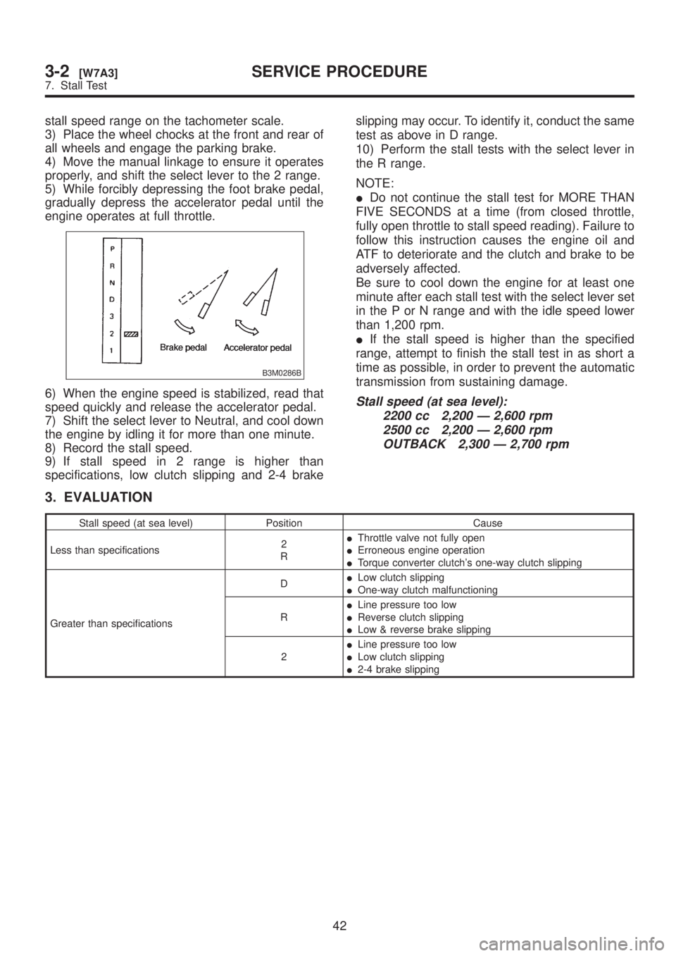
stall speed range on the tachometer scale.
3) Place the wheel chocks at the front and rear of
all wheels and engage the parking brake.
4) Move the manual linkage to ensure it operates
properly, and shift the select lever to the 2 range.
5) While forcibly depressing the foot brake pedal,
gradually depress the accelerator pedal until the
engine operates at full throttle.
B3M0286B
6) When the engine speed is stabilized, read that
speed quickly and release the accelerator pedal.
7) Shift the select lever to Neutral, and cool down
the engine by idling it for more than one minute.
8) Record the stall speed.
9) If stall speed in 2 range is higher than
specifications, low clutch slipping and 2-4 brakeslipping may occur. To identify it, conduct the same
test as above in D range.
10) Perform the stall tests with the select lever in
the R range.
NOTE:
IDo not continue the stall test for MORE THAN
FIVE SECONDS at a time (from closed throttle,
fully open throttle to stall speed reading). Failure to
follow this instruction causes the engine oil and
ATF to deteriorate and the clutch and brake to be
adversely affected.
Be sure to cool down the engine for at least one
minute after each stall test with the select lever set
in the P or N range and with the idle speed lower
than 1,200 rpm.
IIf the stall speed is higher than the specified
range, attempt to finish the stall test in as short a
time as possible, in order to prevent the automatic
transmission from sustaining damage.Stall speed (at sea level):
2200 cc 2,200 Ð 2,600 rpm
2500 cc 2,200 Ð 2,600 rpm
OUTBACK 2,300 Ð 2,700 rpm
3. EVALUATION
Stall speed (at sea level) Position Cause
Less than specifications2
RIThrottle valve not fully open
IErroneous engine operation
ITorque converter clutch's one-way clutch slipping
Greater than specificationsDILow clutch slipping
IOne-way clutch malfunctioning
RILine pressure too low
IReverse clutch slipping
ILow & reverse brake slipping
2ILine pressure too low
ILow clutch slipping
I2-4 brake slipping
42
3-2[W7A3]SERVICE PROCEDURE
7. Stall Test
Page 738 of 1456
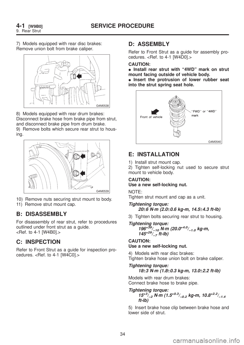
7) Models equipped with rear disc brakes:
Remove union bolt from brake caliper.
G4M0538
8) Models equipped with rear drum brakes:
Disconnect brake hose from brake pipe from strut,
and disconnect brake pipe from drum brake.
9) Remove bolts which secure rear strut to hous-
ing.
G4M0539
10) Remove nuts securing strut mount to body.
11) Remove strut mount cap.
B: DISASSEMBLY
For disassembly of rear strut, refer to procedures
outlined under front strut as a guide.
C: INSPECTION
Refer to Front Strut as a guide for inspection pro-
cedures.
D: ASSEMBLY
Refer to Front Strut as a guide for assembly pro-
cedures.
CAUTION:
IInstall rear strut with ª4WDº mark on strut
mount facing outside of vehicle body.
IInsert the protrusion of lower rubber seat
into the strut spring seat hole.
G4M0540
E: INSTALLATION
1) Install strut mount cap.
2) Tighten self-locking nut used to secure strut
mount to vehicle body.
CAUTION:
Use a new self-locking nut.
NOTE:
Tighten strut mount and cap as a unit.
Tightening torque:
20
±6 N´m (2.0±0.6 kg-m, 14.5±4.3 ft-lb)
3) Tighten bolts securing rear strut to housing.
Tightening torque:
196+39/þ10N´m (20.0+4.0/þ1.0kg-m,
145+29/þ7ft-lb)
CAUTION:
Use a new self-locking nut.
4) Models with rear disc brakes:
Tighten brake hose union bolt on brake caliper.
Tightening torque:
18
±3 N´m (1.8±0.3 kg-m, 13.0±2.2 ft-lb)
Models with rear drum brakes:
Connect brake hose to brake pipe.
Tightening torque:
15+3/þ2N´m (1.5+0.3/þ0.2kg-m, 10.8+2.2/þ1.4ft-lb)
5) Insert brake hose clip between brake hose and
lower side of strut.
34
4-1[W9B0]SERVICE PROCEDURE
9. Rear Strut
Page 766 of 1456
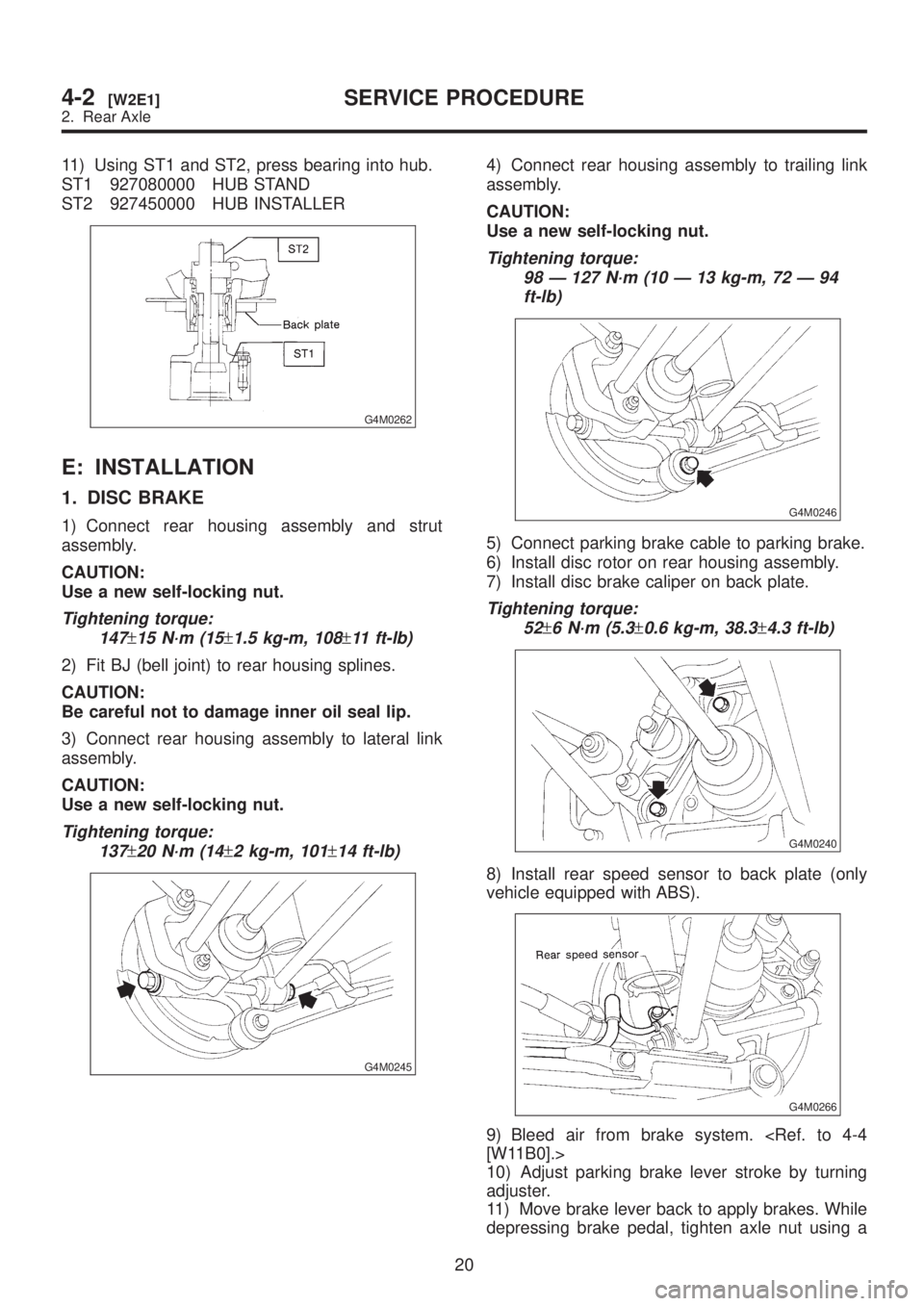
11) Using ST1 and ST2, press bearing into hub.
ST1 927080000 HUB STAND
ST2 927450000 HUB INSTALLER
G4M0262
E: INSTALLATION
1. DISC BRAKE
1) Connect rear housing assembly and strut
assembly.
CAUTION:
Use a new self-locking nut.
Tightening torque:
147
±15 N´m (15±1.5 kg-m, 108±11 ft-lb)
2) Fit BJ (bell joint) to rear housing splines.
CAUTION:
Be careful not to damage inner oil seal lip.
3) Connect rear housing assembly to lateral link
assembly.
CAUTION:
Use a new self-locking nut.
Tightening torque:
137
±20 N´m (14±2 kg-m, 101±14 ft-lb)
G4M0245
4) Connect rear housing assembly to trailing link
assembly.
CAUTION:
Use a new self-locking nut.
Tightening torque:
98 Ð 127 N´m (10 Ð 13 kg-m, 72 Ð 94
ft-lb)
G4M0246
5) Connect parking brake cable to parking brake.
6) Install disc rotor on rear housing assembly.
7) Install disc brake caliper on back plate.
Tightening torque:
52
±6 N´m (5.3±0.6 kg-m, 38.3±4.3 ft-lb)
G4M0240
8) Install rear speed sensor to back plate (only
vehicle equipped with ABS).
G4M0266
9) Bleed air from brake system.
10) Adjust parking brake lever stroke by turning
adjuster.
11) Move brake lever back to apply brakes. While
depressing brake pedal, tighten axle nut using a
20
4-2[W2E1]SERVICE PROCEDURE
2. Rear Axle
Page 767 of 1456
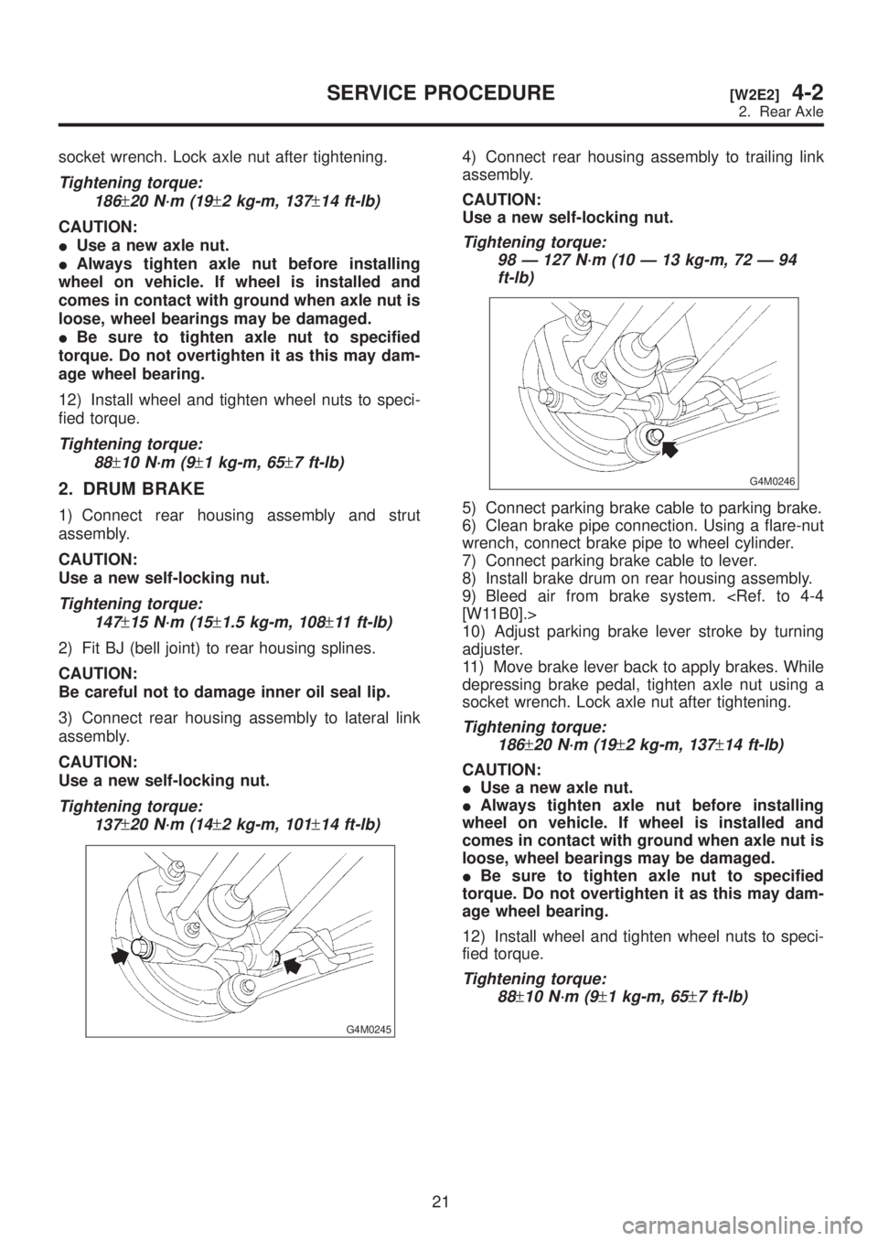
socket wrench. Lock axle nut after tightening.
Tightening torque:
186
±20 N´m (19±2 kg-m, 137±14 ft-lb)
CAUTION:
IUse a new axle nut.
IAlways tighten axle nut before installing
wheel on vehicle. If wheel is installed and
comes in contact with ground when axle nut is
loose, wheel bearings may be damaged.
IBe sure to tighten axle nut to specified
torque. Do not overtighten it as this may dam-
age wheel bearing.
12) Install wheel and tighten wheel nuts to speci-
fied torque.
Tightening torque:
88
±10 N´m (9±1 kg-m, 65±7 ft-lb)
2. DRUM BRAKE
1) Connect rear housing assembly and strut
assembly.
CAUTION:
Use a new self-locking nut.
Tightening torque:
147
±15 N´m (15±1.5 kg-m, 108±11 ft-lb)
2) Fit BJ (bell joint) to rear housing splines.
CAUTION:
Be careful not to damage inner oil seal lip.
3) Connect rear housing assembly to lateral link
assembly.
CAUTION:
Use a new self-locking nut.
Tightening torque:
137
±20 N´m (14±2 kg-m, 101±14 ft-lb)
G4M0245
4) Connect rear housing assembly to trailing link
assembly.
CAUTION:
Use a new self-locking nut.
Tightening torque:
98 Ð 127 N´m (10 Ð 13 kg-m, 72 Ð 94
ft-lb)
G4M0246
5) Connect parking brake cable to parking brake.
6) Clean brake pipe connection. Using a flare-nut
wrench, connect brake pipe to wheel cylinder.
7) Connect parking brake cable to lever.
8) Install brake drum on rear housing assembly.
9) Bleed air from brake system.
10) Adjust parking brake lever stroke by turning
adjuster.
11) Move brake lever back to apply brakes. While
depressing brake pedal, tighten axle nut using a
socket wrench. Lock axle nut after tightening.
Tightening torque:
186
±20 N´m (19±2 kg-m, 137±14 ft-lb)
CAUTION:
IUse a new axle nut.
IAlways tighten axle nut before installing
wheel on vehicle. If wheel is installed and
comes in contact with ground when axle nut is
loose, wheel bearings may be damaged.
IBe sure to tighten axle nut to specified
torque. Do not overtighten it as this may dam-
age wheel bearing.
12) Install wheel and tighten wheel nuts to speci-
fied torque.
Tightening torque:
88
±10 N´m (9±1 kg-m, 65±7 ft-lb)
21
[W2E2]4-2SERVICE PROCEDURE
2. Rear Axle
Page 873 of 1456
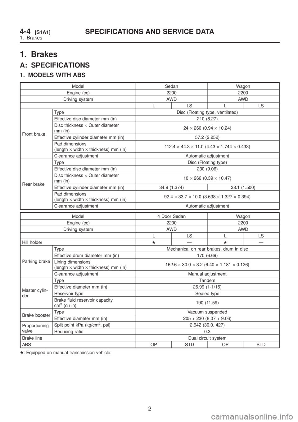
1. Brakes
A: SPECIFICATIONS
1. MODELS WITH ABS
Model Sedan Wagon
Engine (cc) 2200 2200
Driving system AWD AWD
LLSLLS
Front brakeType Disc (Floating type, ventilated)
Effective disc diameter mm (in) 210 (8.27)
Disc thickness´Outer diameter
mm (in)24´260 (0.94´10.24)
Effective cylinder diameter mm (in) 57.2 (2.252)
Pad dimensions
(length´width´thickness) mm (in)112.4´44.3´11.0 (4.43´1.744´0.433)
Clearance adjustment Automatic adjustment
Rear brakeType Disc (Floating type)
Effective disc diameter mm (in) 230 (9.06)
Disc thickness´Outer diameter
mm (in)10´266 (0.39´10.47)
Effective cylinder diameter mm (in) 34.9 (1.374) 38.1 (1.500)
Pad dimensions
(length´width´thickness) mm (in)92.4´33.7´10.0 (3.638´1.327´0.394)
Clearance adjustment Automatic adjustment
Model 4 Door Sedan Wagon
Engine (cc) 2200 2200
Driving system AWD AWD
LLSLLS
Hill holderHÐHÐ
Parking brakeType Mechanical on rear brakes, drum in disc
Effective drum diameter mm (in) 170 (6.69)
Lining dimensions
(length´width´thickness) mm (in)162.6´30.0´3.2 (6.40´1.181´0.126)
Clearance adjustment Manual adjustment
Master cylin-
derType Tandem
Effective diameter mm (in) 26.99 (1-1/16)
Reservoir type Sealed type
Brake fluid reservoir capacity
cm
3(cu in)190 (11.59)
Brake boosterType Vacuum suspended
Effective diameter mm (in) 205 + 230 (8.07 + 9.06)
Proportioning
valveSplit point kPa (kg/cm
2, psi) 2,942 (30.0, 427)
Reducing ratio 0.3
Brake lineDual circuit system
ABS OP STD OP STD
H: Equipped on manual transmission vehicle.
2
4-4[S1A1]SPECIFICATIONS AND SERVICE DATA
1. Brakes
Page 874 of 1456
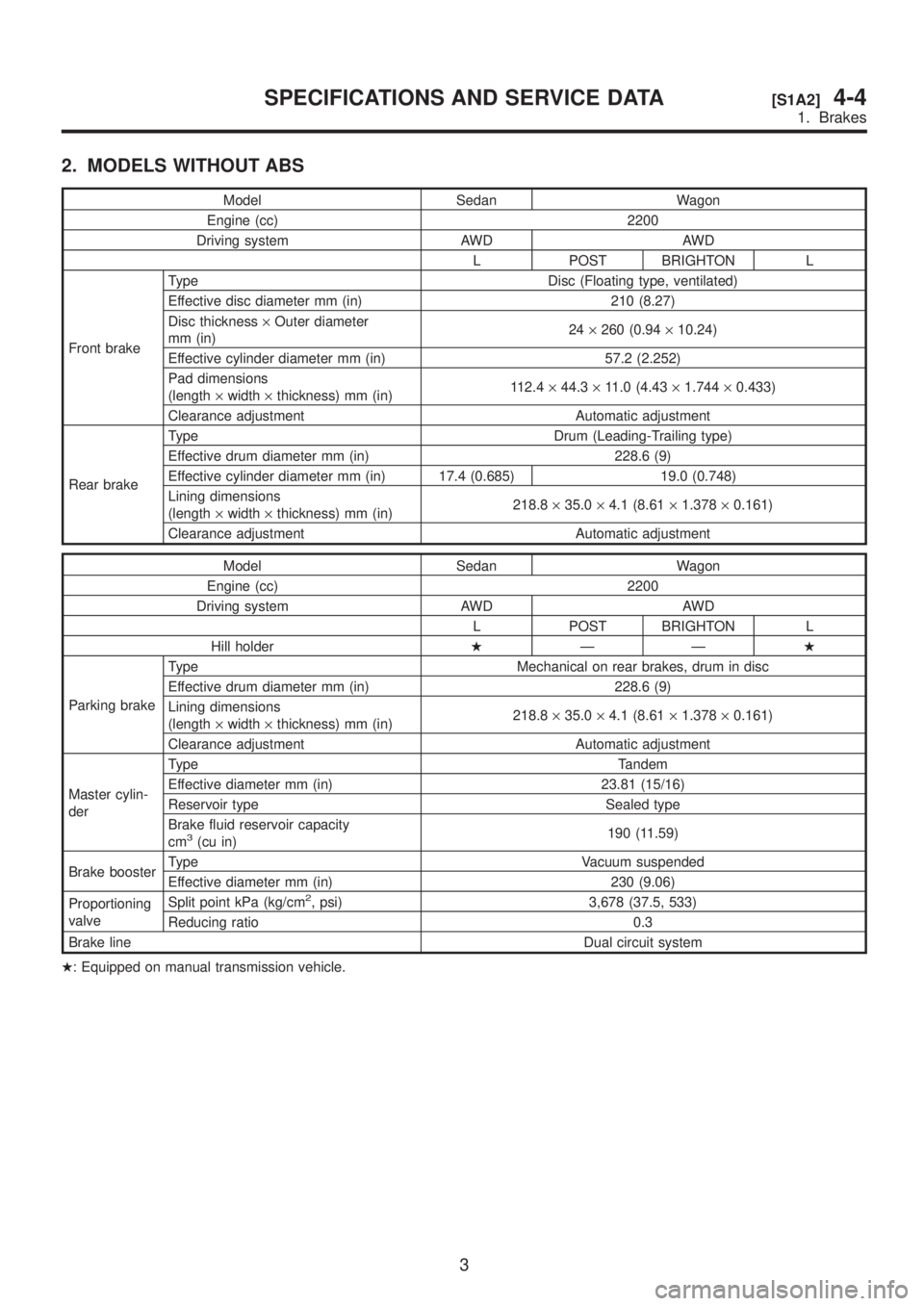
2. MODELS WITHOUT ABS
Model Sedan Wagon
Engine (cc) 2200
Driving system AWD AWD
L POST BRIGHTON L
Front brakeType Disc (Floating type, ventilated)
Effective disc diameter mm (in) 210 (8.27)
Disc thickness´Outer diameter
mm (in)24´260 (0.94´10.24)
Effective cylinder diameter mm (in) 57.2 (2.252)
Pad dimensions
(length´width´thickness) mm (in)112.4´44.3´11.0 (4.43´1.744´0.433)
Clearance adjustment Automatic adjustment
Rear brakeType Drum (Leading-Trailing type)
Effective drum diameter mm (in) 228.6 (9)
Effective cylinder diameter mm (in) 17.4 (0.685) 19.0 (0.748)
Lining dimensions
(length´width´thickness) mm (in)218.8´35.0´4.1 (8.61´1.378´0.161)
Clearance adjustment Automatic adjustment
Model Sedan Wagon
Engine (cc) 2200
Driving system AWD AWD
L POST BRIGHTON L
Hill holderHÐÐH
Parking brakeType Mechanical on rear brakes, drum in disc
Effective drum diameter mm (in) 228.6 (9)
Lining dimensions
(length´width´thickness) mm (in)218.8´35.0´4.1 (8.61´1.378´0.161)
Clearance adjustment Automatic adjustment
Master cylin-
derType Tandem
Effective diameter mm (in) 23.81 (15/16)
Reservoir type Sealed type
Brake fluid reservoir capacity
cm
3(cu in)190 (11.59)
Brake boosterType Vacuum suspended
Effective diameter mm (in) 230 (9.06)
Proportioning
valveSplit point kPa (kg/cm
2, psi) 3,678 (37.5, 533)
Reducing ratio 0.3
Brake lineDual circuit system
H: Equipped on manual transmission vehicle.
3
[S1A2]4-4SPECIFICATIONS AND SERVICE DATA
1. Brakes
Page 875 of 1456
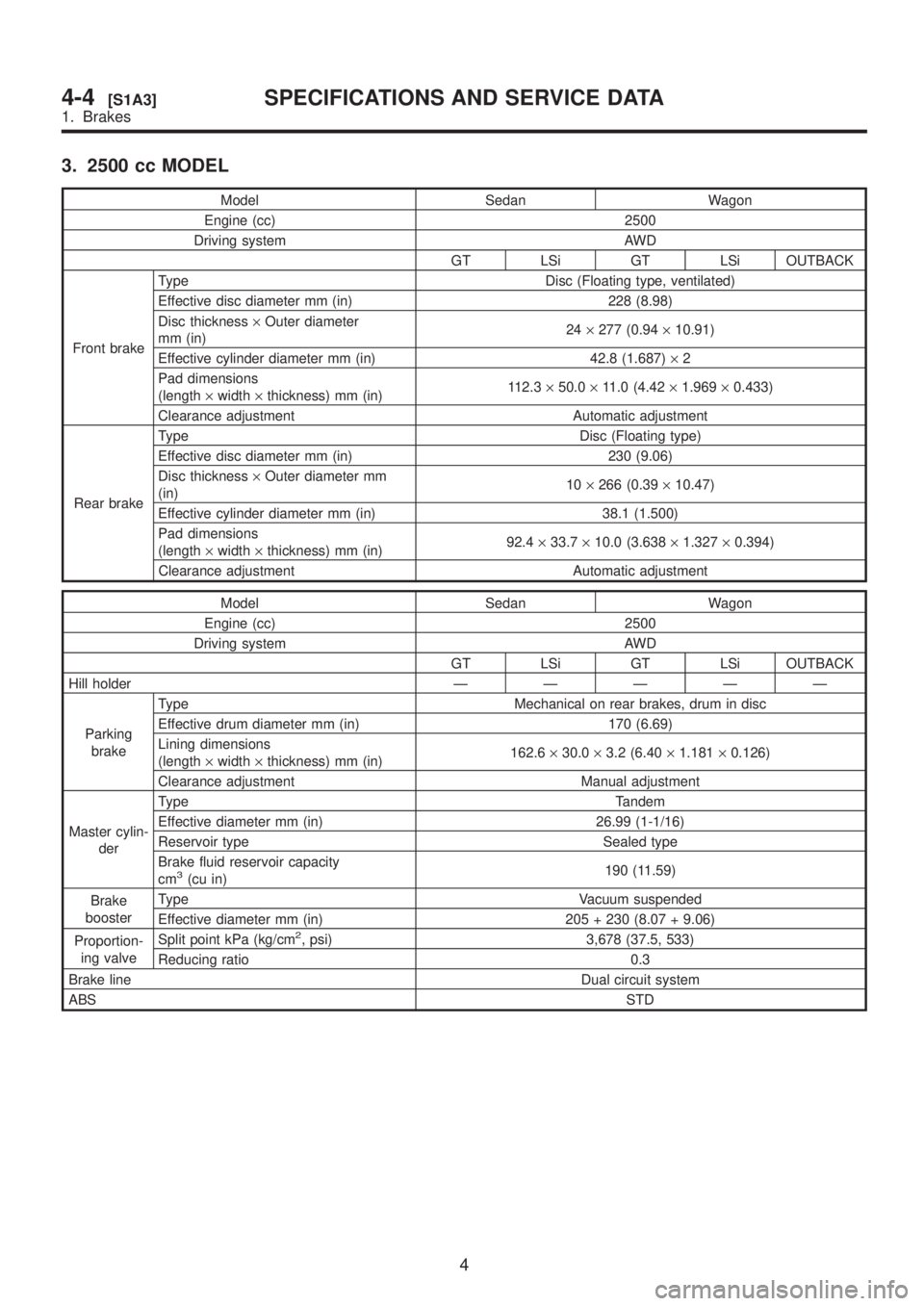
3. 2500 cc MODEL
Model Sedan Wagon
Engine (cc) 2500
Driving system AWD
GT LSi GT LSi OUTBACK
Front brakeType Disc (Floating type, ventilated)
Effective disc diameter mm (in) 228 (8.98)
Disc thickness´Outer diameter
mm (in)24´277 (0.94´10.91)
Effective cylinder diameter mm (in) 42.8 (1.687)´2
Pad dimensions
(length´width´thickness) mm (in)112.3´50.0´11.0 (4.42´1.969´0.433)
Clearance adjustment Automatic adjustment
Rear brakeType Disc (Floating type)
Effective disc diameter mm (in) 230 (9.06)
Disc thickness´Outer diameter mm
(in)10´266 (0.39´10.47)
Effective cylinder diameter mm (in) 38.1 (1.500)
Pad dimensions
(length´width´thickness) mm (in)92.4´33.7´10.0 (3.638´1.327´0.394)
Clearance adjustment Automatic adjustment
Model Sedan Wagon
Engine (cc) 2500
Driving system AWD
GT LSi GT LSi OUTBACK
Hill holderÐÐÐÐÐ
Parking
brakeType Mechanical on rear brakes, drum in disc
Effective drum diameter mm (in) 170 (6.69)
Lining dimensions
(length´width´thickness) mm (in)162.6´30.0´3.2 (6.40´1.181´0.126)
Clearance adjustment Manual adjustment
Master cylin-
derType Tandem
Effective diameter mm (in) 26.99 (1-1/16)
Reservoir type Sealed type
Brake fluid reservoir capacity
cm
3(cu in)190 (11.59)
Brake
boosterType Vacuum suspended
Effective diameter mm (in) 205 + 230 (8.07 + 9.06)
Proportion-
ing valveSplit point kPa (kg/cm
2, psi) 3,678 (37.5, 533)
Reducing ratio 0.3
Brake lineDual circuit system
ABSSTD
4
4-4[S1A3]SPECIFICATIONS AND SERVICE DATA
1. Brakes
Page 876 of 1456
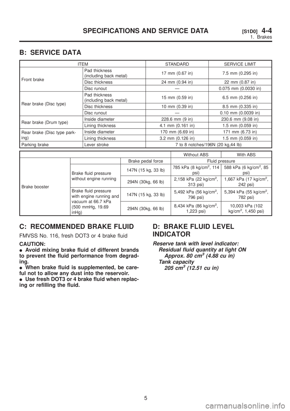
B: SERVICE DATA
ITEM STANDARD SERVICE LIMIT
Front brakePad thickness
(including back metal)17 mm (0.67 in) 7.5 mm (0.295 in)
Disc thickness 24 mm (0.94 in) 22 mm (0.87 in)
Disc runout Ð 0.075 mm (0.0030 in)
Rear brake (Disc type)Pad thickness
(including back metal)15 mm (0.59 in) 6.5 mm (0.256 in)
Disc thickness 10 mm (0.39 in) 8.5 mm (0.335 in)
Disc runout Ð 0.10 mm (0.0039 in)
Rear brake (Drum type)Inside diameter 228.6 mm (9 in) 230.6 mm (9.08 in)
Lining thickness 4.1 mm (0.161 in) 1.5 mm (0.059 in)
Rear brake (Disc type park-
ing)Inside diameter 170 mm (6.69 in) 171 mm (6.73 in)
Lining thickness 3.2 mm (0.126 in) 1.5 mm (0.059 in)
Parking brake Lever stroke 7 to 8 notches/196N (20 kg,44 lb)
Without ABS With ABS
Brake boosterBrake pedal force Fluid pressure
Brake fluid pressure
without engine running147N (15 kg, 33 lb)785 kPa (8 kg/cm
2,114
psi)588 kPa (6 kg/cm2,85
psi)
294N (30kg, 66 lb)2,158 kPa (22 kg/cm
2,
313 psi)1,667 kPa (17 kg/cm2,
242 psi)
Brake fluid pressure
with engine running and
vacuum at 66.7 kPa
(500 mmHg, 19.69
inHg)147N (15 kg, 33 lb)5,492 kPa (56 kg/cm
2,
796 psi)5,394 kPa (55 kg/cm2,
782 psi)
294N (30kg, 66 lb)8,434 kPa (86 kg/cm
2,
1,223 psi)10,003 kPa (102
kg/cm2, 1,450 psi)
C: RECOMMENDED BRAKE FLUID
FMVSS No. 116, fresh DOT3 or 4 brake fluid
CAUTION:
IAvoid mixing brake fluid of different brands
to prevent the fluid performance from degrad-
ing.
IWhen brake fluid is supplemented, be care-
ful not to allow any dust into the reservoir.
IUse fresh DOT3 or 4 brake fluid when replac-
ing or refilling the fluid.
D: BRAKE FLUID LEVEL
INDICATOR
Reserve tank with level indicator:
Residual fluid quantity at light ON
Approx. 80 cm
3(4.88 cu in)
Tank capacity
205 cm
3(12.51 cu in)
5
[S1D0]4-4SPECIFICATIONS AND SERVICE DATA
1. Brakes