tire pressure SUBARU LEGACY 1999 Service Repair Manual
[x] Cancel search | Manufacturer: SUBARU, Model Year: 1999, Model line: LEGACY, Model: SUBARU LEGACY 1999Pages: 1456, PDF Size: 59.93 MB
Page 562 of 1456
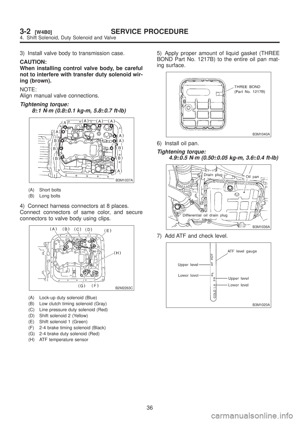
3) Install valve body to transmission case.
CAUTION:
When installing control valve body, be careful
not to interfere with transfer duty solenoid wir-
ing (brown).
NOTE:
Align manual valve connections.
Tightening torque:
8
±1 N´m (0.8±0.1 kg-m, 5.8±0.7 ft-lb)
B3M1037A
(A) Short bolts
(B) Long bolts
4) Connect harness connectors at 8 places.
Connect connectors of same color, and secure
connectors to valve body using clips.
B2M2263C
(A) Lock-up duty solenoid (Blue)
(B) Low clutch timing solenoid (Gray)
(C) Line pressure duty solenoid (Red)
(D) Shift solenoid 2 (Yellow)
(E) Shift solenoid 1 (Green)
(F) 2-4 brake timing solenoid (Black)
(G) 2-4 brake duty solenoid (Red)
(H) ATF temperature sensor
5) Apply proper amount of liquid gasket (THREE
BOND Part No. 1217B) to the entire oil pan mat-
ing surface.
B3M1040A
6) Install oil pan.
Tightening torque:
4.9
±0.5 N´m (0.50±0.05 kg-m, 3.6±0.4 ft-lb)
B3M1036A
7) Add ATF and check level.
B3M1020A
36
3-2[W4B0]SERVICE PROCEDURE
4. Shift Solenoid, Duty Solenoid and Valve
Page 702 of 1456
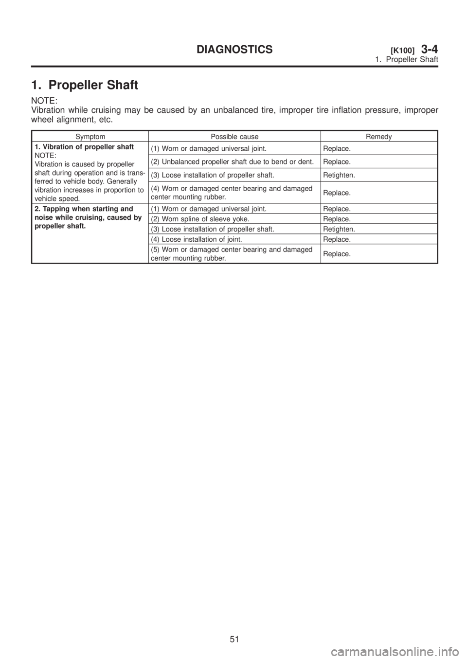
1. Propeller Shaft
NOTE:
Vibration while cruising may be caused by an unbalanced tire, improper tire inflation pressure, improper
wheel alignment, etc.
Symptom Possible cause Remedy
1. Vibration of propeller shaft
NOTE:
Vibration is caused by propeller
shaft during operation and is trans-
ferred to vehicle body. Generally
vibration increases in proportion to
vehicle speed.(1) Worn or damaged universal joint. Replace.
(2) Unbalanced propeller shaft due to bend or dent. Replace.
(3) Loose installation of propeller shaft. Retighten.
(4) Worn or damaged center bearing and damaged
center mounting rubber.Replace.
2. Tapping when starting and
noise while cruising, caused by
propeller shaft.(1) Worn or damaged universal joint. Replace.
(2) Worn spline of sleeve yoke. Replace.
(3) Loose installation of propeller shaft. Retighten.
(4) Loose installation of joint. Replace.
(5) Worn or damaged center bearing and damaged
center mounting rubber.Replace.
51
[K100]3-4DIAGNOSTICS
1. Propeller Shaft
Page 710 of 1456
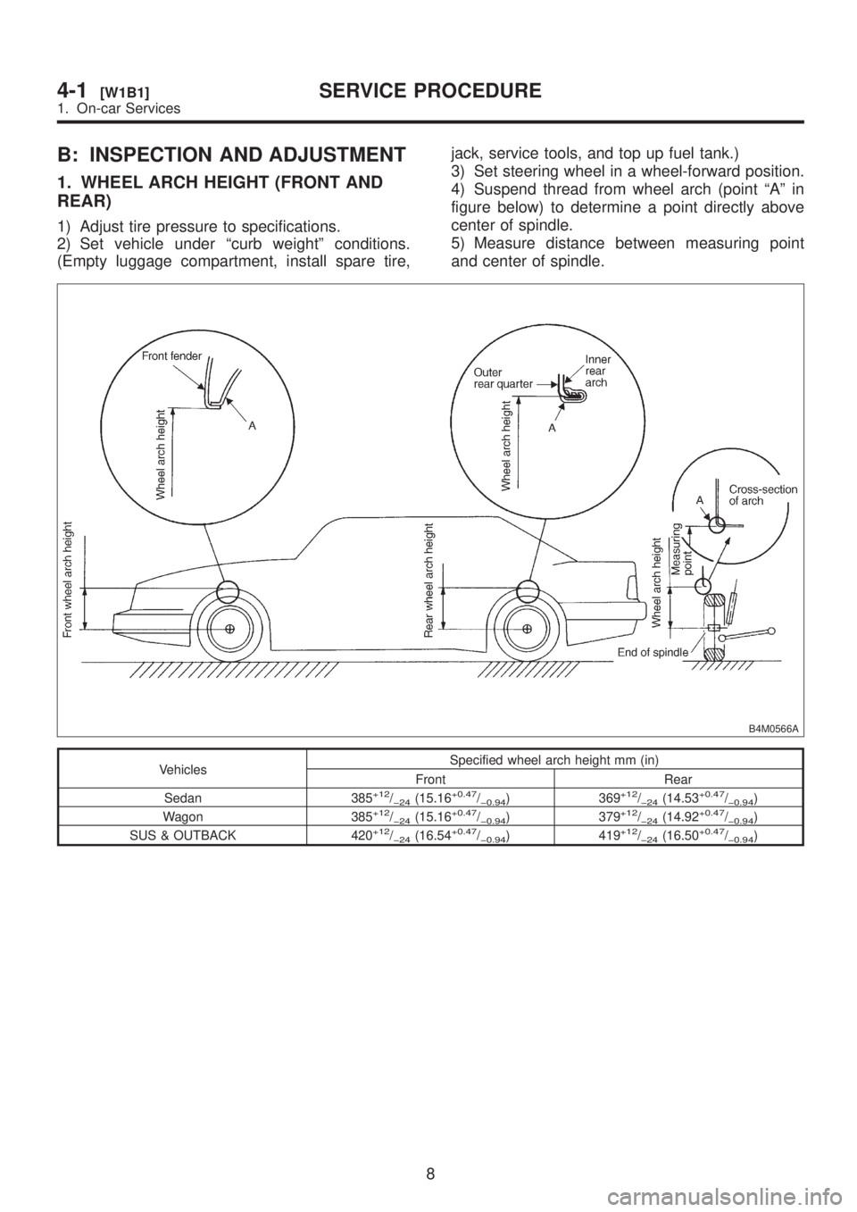
B: INSPECTION AND ADJUSTMENT
1. WHEEL ARCH HEIGHT (FRONT AND
REAR)
1) Adjust tire pressure to specifications.
2) Set vehicle under ªcurb weightº conditions.
(Empty luggage compartment, install spare tire,jack, service tools, and top up fuel tank.)
3) Set steering wheel in a wheel-forward position.
4) Suspend thread from wheel arch (point ªAº in
figure below) to determine a point directly above
center of spindle.
5) Measure distance between measuring point
and center of spindle.
B4M0566A
VehiclesSpecified wheel arch height mm (in)
Front Rear
Sedan 385
+12/þ24(15.16+0.47/þ0.94) 369+12/þ24(14.53+0.47/þ0.94)
Wagon 385+12/þ24(15.16+0.47/þ0.94) 379+12/þ24(14.92+0.47/þ0.94)
SUS & OUTBACK 420+12/þ24(16.54+0.47/þ0.94) 419+12/þ24(16.50+0.47/þ0.94)
8
4-1[W1B1]SERVICE PROCEDURE
1. On-car Services
Page 744 of 1456
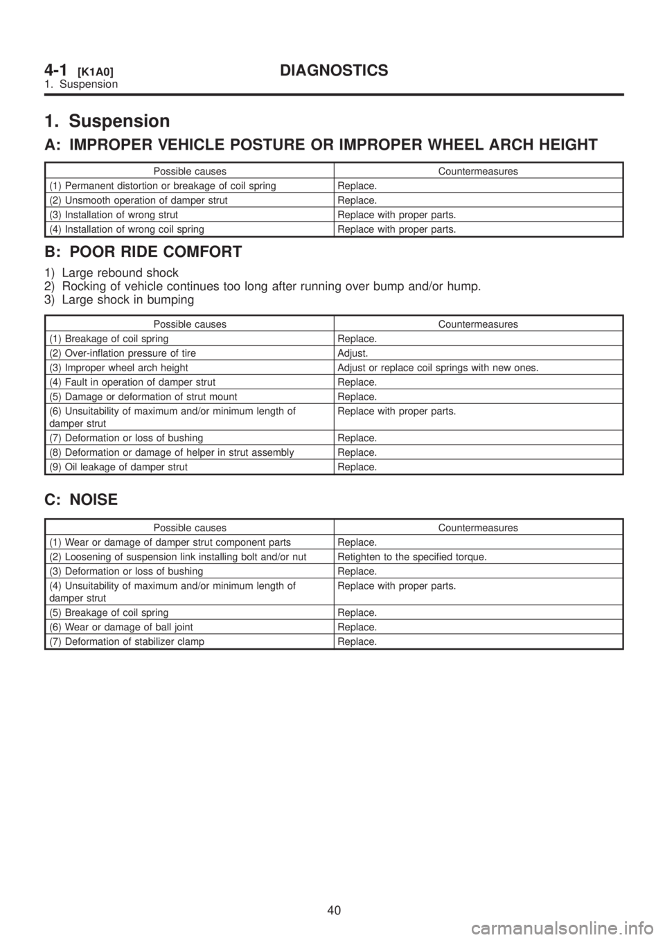
1. Suspension
A: IMPROPER VEHICLE POSTURE OR IMPROPER WHEEL ARCH HEIGHT
Possible causes Countermeasures
(1) Permanent distortion or breakage of coil spring Replace.
(2) Unsmooth operation of damper strut Replace.
(3) Installation of wrong strut Replace with proper parts.
(4) Installation of wrong coil spring Replace with proper parts.
B: POOR RIDE COMFORT
1) Large rebound shock
2) Rocking of vehicle continues too long after running over bump and/or hump.
3) Large shock in bumping
Possible causes Countermeasures
(1) Breakage of coil spring Replace.
(2) Over-inflation pressure of tire Adjust.
(3) Improper wheel arch height Adjust or replace coil springs with new ones.
(4) Fault in operation of damper strut Replace.
(5) Damage or deformation of strut mount Replace.
(6) Unsuitability of maximum and/or minimum length of
damper strutReplace with proper parts.
(7) Deformation or loss of bushing Replace.
(8) Deformation or damage of helper in strut assembly Replace.
(9) Oil leakage of damper strut Replace.
C: NOISE
Possible causes Countermeasures
(1) Wear or damage of damper strut component parts Replace.
(2) Loosening of suspension link installing bolt and/or nut Retighten to the specified torque.
(3) Deformation or loss of bushing Replace.
(4) Unsuitability of maximum and/or minimum length of
damper strutReplace with proper parts.
(5) Breakage of coil spring Replace.
(6) Wear or damage of ball joint Replace.
(7) Deformation of stabilizer clamp Replace.
40
4-1[K1A0]DIAGNOSTICS
1. Suspension
Page 745 of 1456
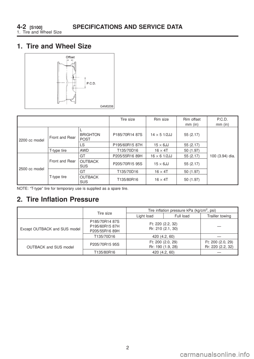
1. Tire and Wheel Size
G4M0208
Tire size Rim size Rim offset
mm (in)P.C.D.
mm (in)
2200 cc modelFront and RearL
BRIGHTON
POSTP185/70R14 87S 14´5 1/2JJ 55 (2.17)
100 (3.94) dia. LS P195/60R15 87H 15´6JJ 55 (2.17)
T-type tire AWD T135/70D16 16´4T 50 (1.97)
2500 cc modelFront and RearGT P205/55R16 89H 16´6 1/2JJ 55 (2.17)
OUTBACK
SUSP205/70R15 95S 15´6JJ 55 (2.17)
T-type tireGT T135/70D16 16´4T 50 (1.97)
OUTBACK
SUST135/80R16 16´4T 50 (1.97)
NOTE: ªT-typeº tire for temporary use is supplied as a spare tire.
2. Tire Inflation Pressure
Tire sizeTire inflation pressure kPa (kg/cm
2, psi)
Light load Full load Trailler towing
Except OUTBACK and SUS modelP185/70R14 87S
P195/60R15 87H
P205/55R16 89HFt: 220 (2.2, 32)
Rr: 210 (2.1, 30)Ð
T135/70D16 420 (4.2, 60) Ð
OUTBACK and SUS modelP205/70R15 95SFt: 200 (2.0, 29)
Rr: 190 (1.9, 28)Ft: 200 (2.0, 29)
Rr: 220 (2.2, 32)
T135/80R16 420 (4.2, 60) Ð
2
4-2[S100]SPECIFICATIONS AND SERVICE DATA
1. Tire and Wheel Size
Page 746 of 1456
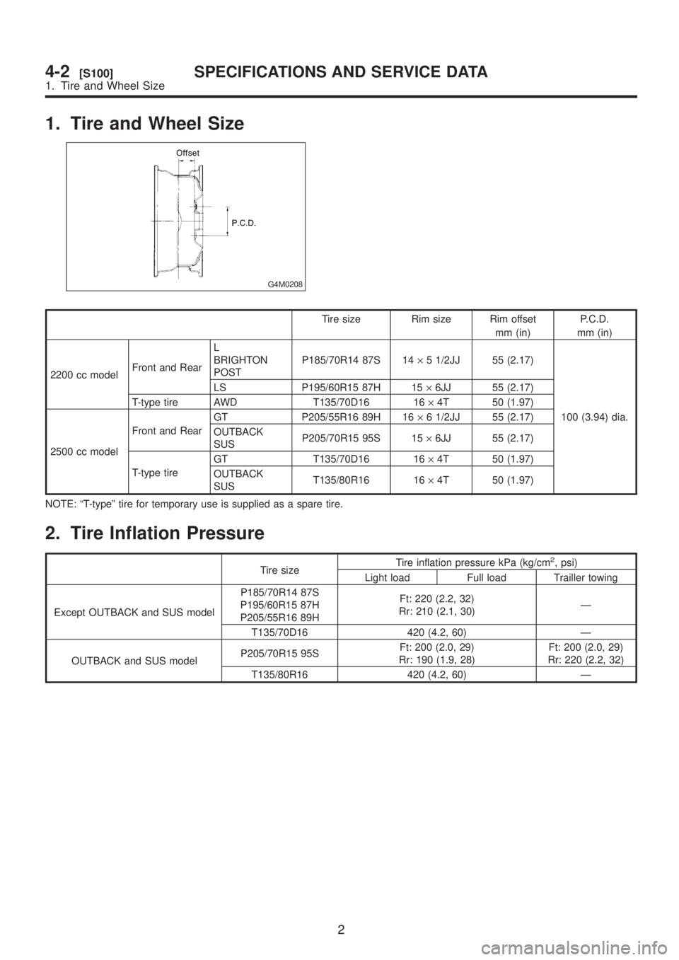
1. Tire and Wheel Size
G4M0208
Tire size Rim size Rim offset
mm (in)P.C.D.
mm (in)
2200 cc modelFront and RearL
BRIGHTON
POSTP185/70R14 87S 14´5 1/2JJ 55 (2.17)
100 (3.94) dia. LS P195/60R15 87H 15´6JJ 55 (2.17)
T-type tire AWD T135/70D16 16´4T 50 (1.97)
2500 cc modelFront and RearGT P205/55R16 89H 16´6 1/2JJ 55 (2.17)
OUTBACK
SUSP205/70R15 95S 15´6JJ 55 (2.17)
T-type tireGT T135/70D16 16´4T 50 (1.97)
OUTBACK
SUST135/80R16 16´4T 50 (1.97)
NOTE: ªT-typeº tire for temporary use is supplied as a spare tire.
2. Tire Inflation Pressure
Tire sizeTire inflation pressure kPa (kg/cm
2, psi)
Light load Full load Trailler towing
Except OUTBACK and SUS modelP185/70R14 87S
P195/60R15 87H
P205/55R16 89HFt: 220 (2.2, 32)
Rr: 210 (2.1, 30)Ð
T135/70D16 420 (4.2, 60) Ð
OUTBACK and SUS modelP205/70R15 95SFt: 200 (2.0, 29)
Rr: 190 (1.9, 28)Ft: 200 (2.0, 29)
Rr: 220 (2.2, 32)
T135/80R16 420 (4.2, 60) Ð
2
4-2[S100]SPECIFICATIONS AND SERVICE DATA
1. Tire and Wheel Size
Page 792 of 1456
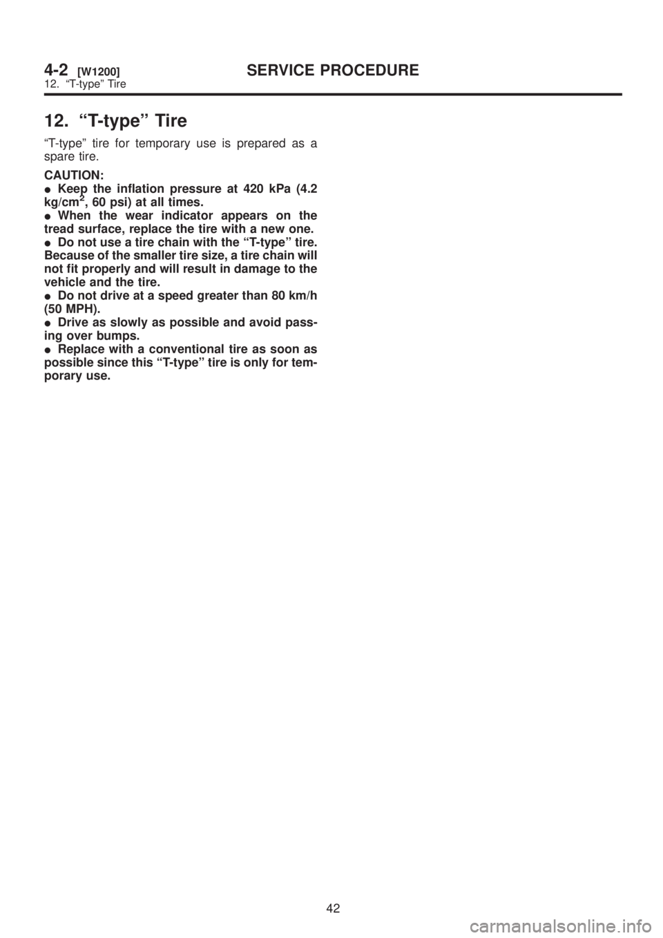
12. ªT-typeº Tire
ªT-typeº tire for temporary use is prepared as a
spare tire.
CAUTION:
IKeep the inflation pressure at 420 kPa (4.2
kg/cm
2, 60 psi) at all times.
IWhen the wear indicator appears on the
tread surface, replace the tire with a new one.
IDo not use a tire chain with the ªT-typeº tire.
Because of the smaller tire size, a tire chain will
not fit properly and will result in damage to the
vehicle and the tire.
IDo not drive at a speed greater than 80 km/h
(50 MPH).
IDrive as slowly as possible and avoid pass-
ing over bumps.
IReplace with a conventional tire as soon as
possible since this ªT-typeº tire is only for tem-
porary use.
42
4-2[W1200]SERVICE PROCEDURE
12. ªT-typeº Tire
Page 793 of 1456
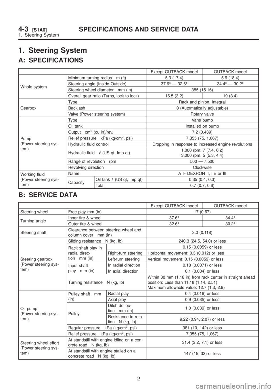
1. Steering System
A: SPECIFICATIONS
Except OUTBACK model OUTBACK model
Whole systemMinimum turning radius m (ft) 5.3 (17.4) 5.6 (18.4)
Steering angle (Inside-Outside) 37.6É Ð 32.6É 34.4É Ð 30.2É
Steering wheel diameter mm (in) 385 (15.16)
Overall gear ratio (Turns, lock to lock) 16.5 (3.2) 19 (3.4)
GearboxType Rack and pinion, Integral
Backlash 0 (Automatically adjustable)
Valve (Power steering system) Rotary valve
Pump
(Power steering sys-
tem)Type Vane pump
Oil tank Installed on pump
Output cm
3(cu in)/rev. 7.2 (0.439)
Relief pressure kPa (kg/cm2, psi) 7,355 (75, 1,067)
Hydraulic fluid control Dropping in response to increased engine revolutions
Hydraulic fluid(US qt, Imp qt)1,000 rpm: 7 (7.4, 6.2)
3,000 rpm: 5 (5.3, 4.4)
Range of revolution rpm 500 Ð 7,500
Revolving direction Clockwise
Working fluid
(Power steering sys-
tem)Name ATF DEXRON II, IIE or III
CapacityOil tank(US qt, Imp qt) 0.35 (0.4, 0.3)
Total 0.7 (0.7, 0.6)
B: SERVICE DATA
Except OUTBACK model OUTBACK model
Steering wheel Free play mm (in) 17 (0.67)
Turning angleInner tire & wheel 37.6É 34.4É
Outer tire & wheel 32.6É 30.2É
Steering shaftClearance between steering wheel and
column cover mm (in)3.0 (0.118)
Steering gearbox
(Power steering sys-
tem)Sliding resistance N (kg, lb) 240.3 (24.5, 54.0) or less
Rack shaft play in
radial direc-
tion mm (in)0.15 (0.0059) or less
Right-turn steering Horizontal movement: 0.3 (0.012) or less
Left-turn steering Vertical movement: 0.15 (0.0059) or less
Input shaft
play mm (in)In radial direction 0.18 (0.0071) or less
In axial direction 0.1 (0.004) or less
Turning resistance N (kg, lb)Within 30 mm (1.18 in) from rack center in straight ahead
position: Less than 11.18 (1.14, 2.51)
Maximum allowable value: 12.7 (1.3, 2.9)
Oil pump
(Power steering sys-
tem)Pulley shaft mm
(in)Radial play 0.4 (0.016) or less
Axial play 0.9 (0.035) or less
PulleyDitch deflec-
tion mm (in)1.0 (0.039) or less
Resistance to rota-
tion N (kg, lb)9.22 (0.94, 2.07) or less
Regular pressure kPa (kg/cm
2, psi) 981 (10, 142) or less
Relief pressure kPa (kg/cm2, psi) 7,355 (75, 1,067)
Steering wheel effort
(Power steering sys-
tem)At standstill with engine idling on a con-
crete road N (kg, lb)31.4 (3.2, 7.1) or less
At standstill with engine stalled on a
concrete road N (kg, lb)147 (15, 33) or less
2
4-3[S1A0]SPECIFICATIONS AND SERVICE DATA
1. Steering System
Page 863 of 1456
1. Power Steering
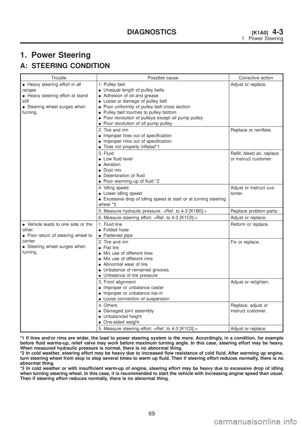
A: STEERING CONDITION
Trouble Possible cause Corrective action
IHeavy steering effort in all
ranges
IHeavy steering effort at stand
still
ISteering wheel surges when
turning.1. Pulley belt
IUnequal length of pulley belts
IAdhesion of oil and grease
ILoose or damage of pulley belt
IPoor uniformity of pulley belt cross section
IPulley belt touches to pulley bottom
IPoor revolution of pulleys except oil pump pulley
IPoor revolution of oil pump pulleyAdjust or replace.
2. Tire and rim
IImproper tires out of specification
IImproper rims out of specification
ITires not properly inflated*1Replace or reinflate.
3. Fluid
ILow fluid level
IAeration
IDust mix
IDeterioration of fluid
IPoor warming-up of fluid *2Refill, bleed air, replace
or instruct customer.
4. Idling speed
ILower idling speed
IExcessive drop of idling speed at start or at turning steering
wheel *3Adjust or instruct cus-
tomer.
5. Measure hydraulic pressure.
6. Measure steering effort.
IVehicle leads to one side or the
other.
IPoor return of steering wheel to
center
ISteering wheel surges when
turning.1. Fluid line
IFolded hose
IFlattened pipeReform or replace.
2. Tire and rim
IFlat tire
IMix use of different tires
IMix use of different rims
IAbnormal wear of tire
IUnbalance of remained grooves
IUnbalance of tire pressureFix or replace.
3. Front alignment
IImproper or unbalance caster
IImproper or unbalance toe-in
ILoose connection of suspensionAdjust or retighten.
4. Others
IDamaged joint assembly
IUnbalanced height
IOne-sided weightReplace, adjust or
instruct customer.
5. Measure steering effort.
*1 If tires and/or rims are wider, the load to power steering system is the more. Accordingly, in a condition, for example
before fluid warms-up, relief valve may work before maximum turning angle. In this case, steering effort may be heavy.
When measured hydraulic pressure is normal, there is no abnormal thing.
*2 In cold weather, steering effort may be heavy due to increased flow resistance of cold fluid. After warming up engine,
turn steering wheel from stop to stop several times to warm up fluid. Then if steering effort reduces normally, there is no
abnormal thing.
*3 In cold weather or with insufficient warm-up of engine, steering effort may be heavy due to excessive drop of idling
when turning steering wheel. In this case, it is recommended to start the vehicle with increasing engine speed than usual.
Then if steering effort reduces normally, there is no abnormal thing.
69
[K1A0]4-3DIAGNOSTICS
1. Power Steering
Page 900 of 1456
4) Raise caliper body and move it toward vehicle
center to separate it from support.
5) Remove support from back plate.
NOTE:
Remove support only when replacing it or the rotor.
It need not be removed when servicing caliper
body assembly.
6) Clean mud and foreign particles from caliper
body assembly and support.
CAUTION:
Be careful not to allow foreign particles to enter
inlet (at brake hose connector).
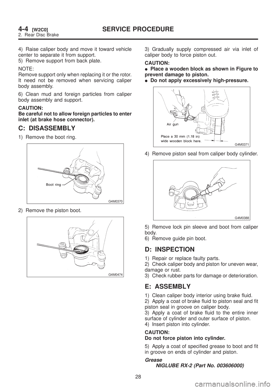
C: DISASSEMBLY
1) Remove the boot ring.
G4M0370
2) Remove the piston boot.
G4M0474
3) Gradually supply compressed air via inlet of
caliper body to force piston out.
CAUTION:
IPlace a wooden block as shown in Figure to
prevent damage to piston.
IDo not apply excessively high-pressure.
G4M0371
4) Remove piston seal from caliper body cylinder.
G4M0388
5) Remove lock pin sleeve and boot from caliper
body.
6) Remove guide pin boot.
D: INSPECTION
1) Repair or replace faulty parts.
2) Check caliper body and piston for uneven wear,
damage or rust.
3) Check rubber parts for damage or deterioration.
E: ASSEMBLY
1) Clean caliper body interior using brake fluid.
2) Apply a coat of brake fluid to piston seal and fit
piston seal in groove on caliper body.
3) Apply a coat of brake fluid to the entire inner
surface of cylinder and outer surface of piston.
4) Insert piston into cylinder.
CAUTION:
Do not force piston into cylinder.
5) Apply a coat of specified grease to boot and fit
in groove on ends of cylinder and piston.
Grease
NIGLUBE RX-2 (Part No. 003606000)
28
4-4[W2C0]SERVICE PROCEDURE
2. Rear Disc Brake