torque SUBARU LEGACY 1999 Service Repair Manual
[x] Cancel search | Manufacturer: SUBARU, Model Year: 1999, Model line: LEGACY, Model: SUBARU LEGACY 1999Pages: 1456, PDF Size: 59.93 MB
Page 2 of 1456
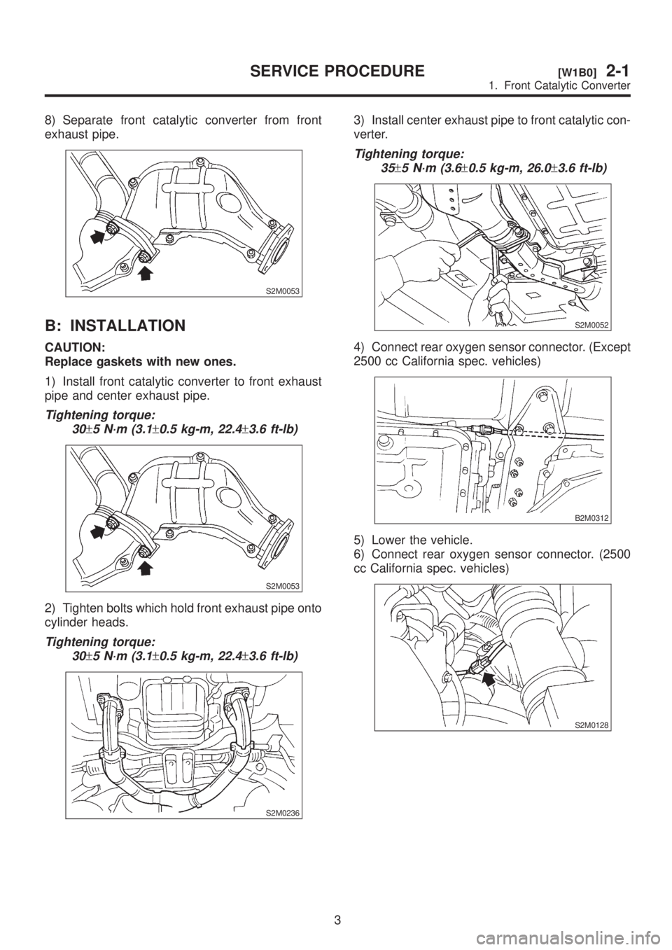
8) Separate front catalytic converter from front
exhaust pipe.
S2M0053
B: INSTALLATION
CAUTION:
Replace gaskets with new ones.
1) Install front catalytic converter to front exhaust
pipe and center exhaust pipe.
Tightening torque:
30
±5 N´m (3.1±0.5 kg-m, 22.4±3.6 ft-lb)
S2M0053
2) Tighten bolts which hold front exhaust pipe onto
cylinder heads.
Tightening torque:
30
±5 N´m (3.1±0.5 kg-m, 22.4±3.6 ft-lb)
S2M0236
3) Install center exhaust pipe to front catalytic con-
verter.
Tightening torque:
35
±5 N´m (3.6±0.5 kg-m, 26.0±3.6 ft-lb)
S2M0052
4) Connect rear oxygen sensor connector. (Except
2500 cc California spec. vehicles)
B2M0312
5) Lower the vehicle.
6) Connect rear oxygen sensor connector. (2500
cc California spec. vehicles)
S2M0128
3
[W1B0]2-1SERVICE PROCEDURE
1. Front Catalytic Converter
Page 5 of 1456
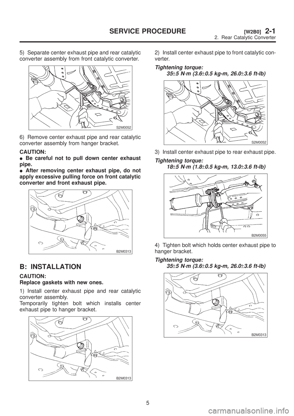
5) Separate center exhaust pipe and rear catalytic
converter assembly from front catalytic converter.
S2M0052
6) Remove center exhaust pipe and rear catalytic
converter assembly from hanger bracket.
CAUTION:
IBe careful not to pull down center exhaust
pipe.
IAfter removing center exhaust pipe, do not
apply excessive pulling force on front catalytic
converter and front exhaust pipe.
B2M0313
B: INSTALLATION
CAUTION:
Replace gaskets with new ones.
1) Install center exhaust pipe and rear catalytic
converter assembly.
Temporarily tighten bolt which installs center
exhaust pipe to hanger bracket.
B2M0313
2) Install center exhaust pipe to front catalytic con-
verter.
Tightening torque:
35
±5 N´m (3.6±0.5 kg-m, 26.0±3.6 ft-lb)
S2M0052
3) Install center exhaust pipe to rear exhaust pipe.
Tightening torque:
18
±5 N´m (1.8±0.5 kg-m, 13.0±3.6 ft-lb)
B2M0055
4) Tighten bolt which holds center exhaust pipe to
hanger bracket.
Tightening torque:
35
±5 N´m (3.6±0.5 kg-m, 26.0±3.6 ft-lb)
B2M0313
5
[W2B0]2-1SERVICE PROCEDURE
2. Rear Catalytic Converter
Page 8 of 1456
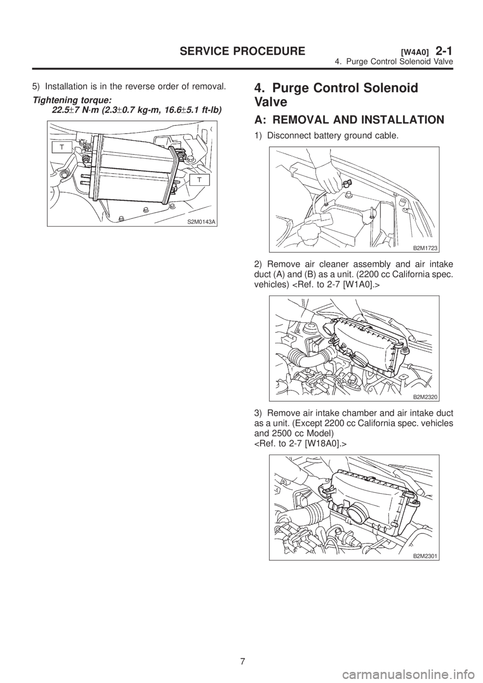
5) Installation is in the reverse order of removal.
Tightening torque:
22.5
±7 N´m (2.3±0.7 kg-m, 16.6±5.1 ft-lb)
S2M0143A
4. Purge Control Solenoid
Valve
A: REMOVAL AND INSTALLATION
1) Disconnect battery ground cable.
B2M1723
2) Remove air cleaner assembly and air intake
duct (A) and (B) as a unit. (2200 cc California spec.
vehicles)
B2M2320
3) Remove air intake chamber and air intake duct
as a unit. (Except 2200 cc California spec. vehicles
and 2500 cc Model)
B2M2301
7
[W4A0]2-1SERVICE PROCEDURE
4. Purge Control Solenoid Valve
Page 9 of 1456
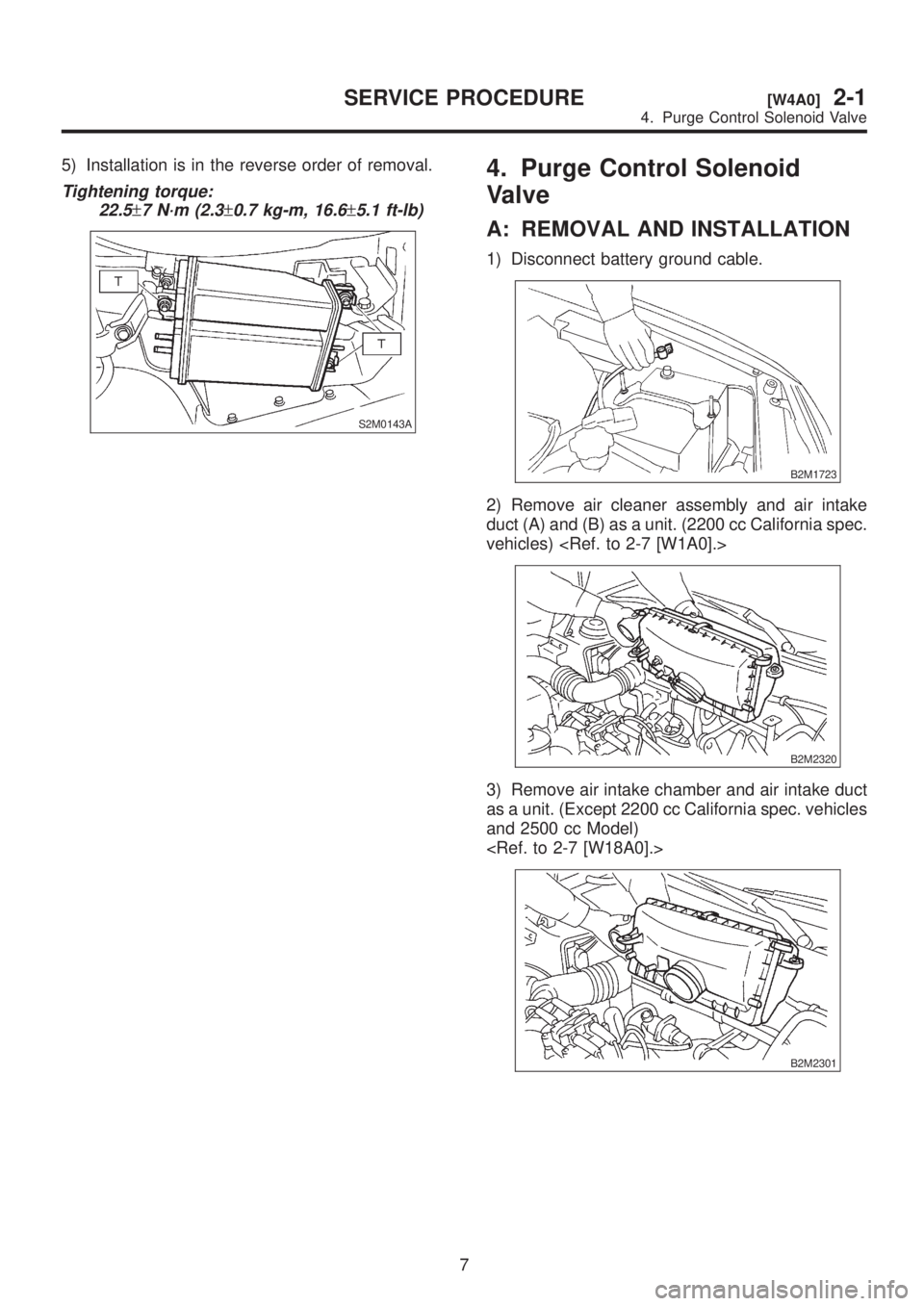
5) Installation is in the reverse order of removal.
Tightening torque:
22.5
±7 N´m (2.3±0.7 kg-m, 16.6±5.1 ft-lb)
S2M0143A
4. Purge Control Solenoid
Valve
A: REMOVAL AND INSTALLATION
1) Disconnect battery ground cable.
B2M1723
2) Remove air cleaner assembly and air intake
duct (A) and (B) as a unit. (2200 cc California spec.
vehicles)
B2M2320
3) Remove air intake chamber and air intake duct
as a unit. (Except 2200 cc California spec. vehicles
and 2500 cc Model)
B2M2301
7
[W4A0]2-1SERVICE PROCEDURE
4. Purge Control Solenoid Valve
Page 10 of 1456
S6M0007A
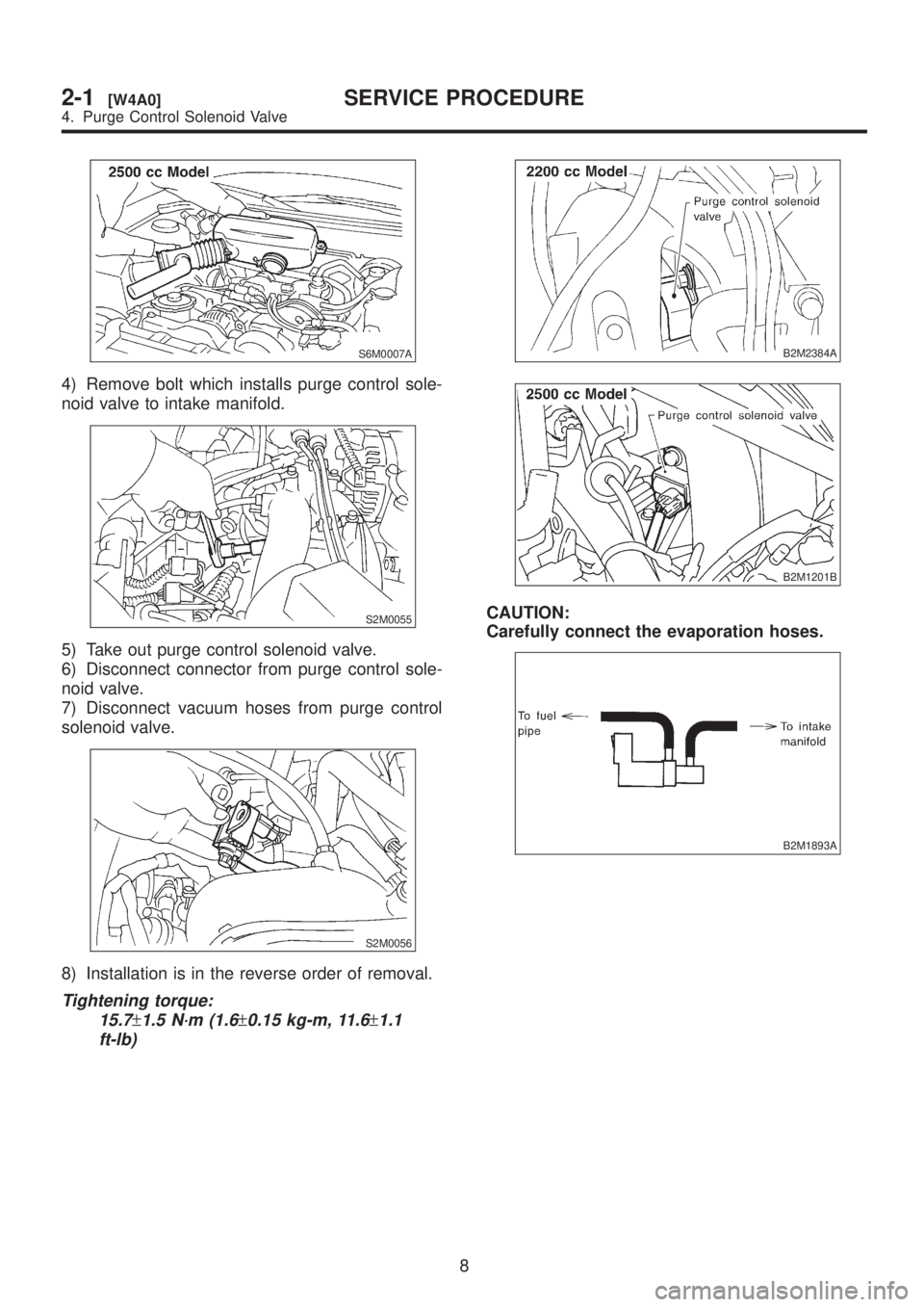
4) Remove bolt which installs purge control sole-
noid valve to intake manifold.
S2M0055
5) Take out purge control solenoid valve.
6) Disconnect connector from purge control sole-
noid valve.
7) Disconnect vacuum hoses from purge control
solenoid valve.
S2M0056
8) Installation is in the reverse order of removal.
Tightening torque:
15.7
±1.5 N´m (1.6±0.15 kg-m, 11.6±1.1
ft-lb)
B2M2384A
B2M1201B
CAUTION:
Carefully connect the evaporation hoses.
B2M1893A
8
2-1[W4A0]SERVICE PROCEDURE
4. Purge Control Solenoid Valve
Page 11 of 1456
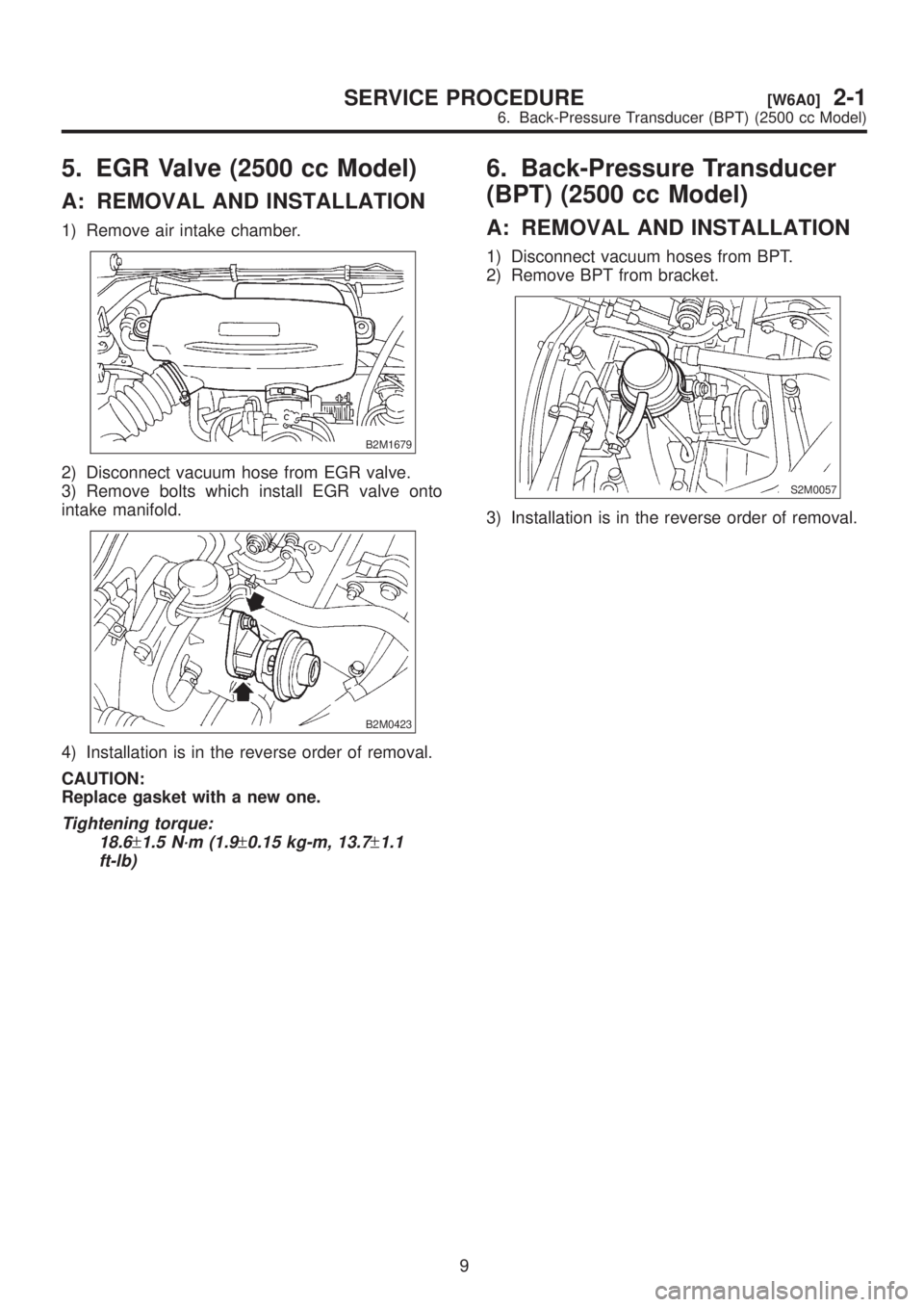
5. EGR Valve (2500 cc Model)
A: REMOVAL AND INSTALLATION
1) Remove air intake chamber.
B2M1679
2) Disconnect vacuum hose from EGR valve.
3) Remove bolts which install EGR valve onto
intake manifold.
B2M0423
4) Installation is in the reverse order of removal.
CAUTION:
Replace gasket with a new one.
Tightening torque:
18.6
±1.5 N´m (1.9±0.15 kg-m, 13.7±1.1
ft-lb)
6. Back-Pressure Transducer
(BPT) (2500 cc Model)
A: REMOVAL AND INSTALLATION
1) Disconnect vacuum hoses from BPT.
2) Remove BPT from bracket.
S2M0057
3) Installation is in the reverse order of removal.
9
[W6A0]2-1SERVICE PROCEDURE
6. Back-Pressure Transducer (BPT) (2500 cc Model)
Page 12 of 1456
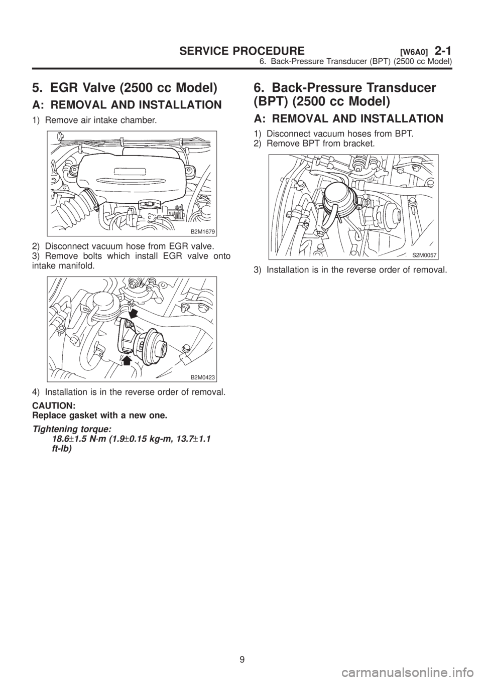
5. EGR Valve (2500 cc Model)
A: REMOVAL AND INSTALLATION
1) Remove air intake chamber.
B2M1679
2) Disconnect vacuum hose from EGR valve.
3) Remove bolts which install EGR valve onto
intake manifold.
B2M0423
4) Installation is in the reverse order of removal.
CAUTION:
Replace gasket with a new one.
Tightening torque:
18.6
±1.5 N´m (1.9±0.15 kg-m, 13.7±1.1
ft-lb)
6. Back-Pressure Transducer
(BPT) (2500 cc Model)
A: REMOVAL AND INSTALLATION
1) Disconnect vacuum hoses from BPT.
2) Remove BPT from bracket.
S2M0057
3) Installation is in the reverse order of removal.
9
[W6A0]2-1SERVICE PROCEDURE
6. Back-Pressure Transducer (BPT) (2500 cc Model)
Page 13 of 1456
![SUBARU LEGACY 1999 Service Repair Manual 7. EGR Solenoid Valve (2500 cc
Model)
A: REMOVAL AND INSTALLATION
1) Disconnect battery ground cable.
B2M1723
2) Remove air intake chamber. <Ref. to 2-7
[W18A0].>
B2M1679
3) Disconnect vacuum hoses fr SUBARU LEGACY 1999 Service Repair Manual 7. EGR Solenoid Valve (2500 cc
Model)
A: REMOVAL AND INSTALLATION
1) Disconnect battery ground cable.
B2M1723
2) Remove air intake chamber. <Ref. to 2-7
[W18A0].>
B2M1679
3) Disconnect vacuum hoses fr](/img/17/57435/w960_57435-12.png)
7. EGR Solenoid Valve (2500 cc
Model)
A: REMOVAL AND INSTALLATION
1) Disconnect battery ground cable.
B2M1723
2) Remove air intake chamber.
B2M1679
3) Disconnect vacuum hoses from EGR solenoid
valve.
4) Disconnect connector from EGR solenoid
valve.
S2M0058A
5) Remove bolt which installs EGR solenoid valve
onto intake manifold.
S2M0059
6) Installation is in the reverse order of removal.
Tightening torque:
15.7
±1.5 N´m (1.6±0.15 kg-m, 11.6±1.1
ft-lb)
10
2-1[W7A0]SERVICE PROCEDURE
7. EGR Solenoid Valve (2500 cc Model)
Page 15 of 1456
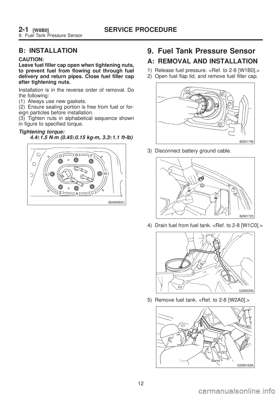
B: INSTALLATION
CAUTION:
Leave fuel filler cap open when tightening nuts,
to prevent fuel from flowing out through fuel
delivery and return pipes. Close fuel filler cap
after tightening nuts.
Installation is in the reverse order of removal. Do
the following:
(1) Always use new gaskets.
(2) Ensure sealing portion is free from fuel or for-
eign particles before installation.
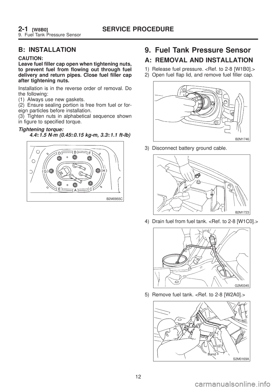
(3) Tighten nuts in alphabetical sequence shown
in figure to specified torque.
Tightening torque:
4.4
±1.5 N´m (0.45±0.15 kg-m, 3.3±1.1 ft-lb)
B2M0955C
9. Fuel Tank Pressure Sensor
A: REMOVAL AND INSTALLATION
1) Release fuel pressure.
2) Open fuel flap lid, and remove fuel filler cap.
B2M1746
3) Disconnect battery ground cable.
B2M1723
4) Drain fuel from fuel tank.
G2M0345
5) Remove fuel tank.
S2M0169A
12
2-1[W8B0]SERVICE PROCEDURE
9. Fuel Tank Pressure Sensor
Page 16 of 1456
B: INSTALLATION
CAUTION:
Leave fuel filler cap open when tightening nuts,
to prevent fuel from flowing out through fuel
delivery and return pipes. Close fuel filler cap
after tightening nuts.
Installation is in the reverse order of removal. Do
the following:
(1) Always use new gaskets.
(2) Ensure sealing portion is free from fuel or for-
eign particles before installation.
(3) Tighten nuts in alphabetical sequence shown
in figure to specified torque.
Tightening torque:
4.4
±1.5 N´m (0.45±0.15 kg-m, 3.3±1.1 ft-lb)
B2M0955C
9. Fuel Tank Pressure Sensor
A: REMOVAL AND INSTALLATION
1) Release fuel pressure.
2) Open fuel flap lid, and remove fuel filler cap.
B2M1746
3) Disconnect battery ground cable.
B2M1723
4) Drain fuel from fuel tank.
G2M0345
5) Remove fuel tank.
S2M0169A
12
2-1[W8B0]SERVICE PROCEDURE
9. Fuel Tank Pressure Sensor