engine SUBARU LEGACY 2005 4.G User Guide
[x] Cancel search | Manufacturer: SUBARU, Model Year: 2005, Model line: LEGACY, Model: SUBARU LEGACY 2005 4.GPages: 627, PDF Size: 6.42 MB
Page 149 of 627
2-24
Keys and doors
To activate:
Repeat moving the door locking switch to the lock po-
sition (toward the front) three times. The odometer/trip
meter screen will display “AL ON”.
When the setting has been successfully changed, a
buzzer will sound and the odometer/trip meter screen
will display the new setting.
NOTE
You may have the above setting change done by
your SUBARU dealer. !
If you have accidentally triggered the
alarm system
! To stop the alarm
Do any of the following operations: " Insert the key in the door lock of the driver’s door
and turn it to the unlock position. " Press any button on the remote transmitter.
" Turn the ignition switch to the “ON” position (only
vehicle with immobilizer)." Cycle the ignition switch from the “LOCK” to “ON”
position three times within 5 seconds (only vehicle
without immobilizer). !
Arming the system
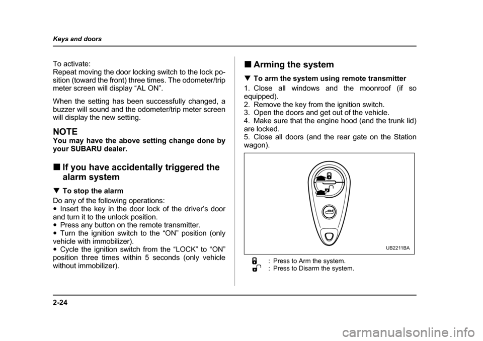
! To arm the system using remote transmitter
1. Close all windows and the moonroof (if so
equipped).
2. Remove the key from the ignition switch.
3. Open the doors and get out of the vehicle.
4. Make sure that the engine hood (and the trunk lid)
are locked.
5. Close all doors (and the rear gate on the Station
wagon).
: Press to Arm the system.
: Press to Disarm the system.
UB2211BA
Page 150 of 627
2-25
Keys and doors
– CONTINUED –
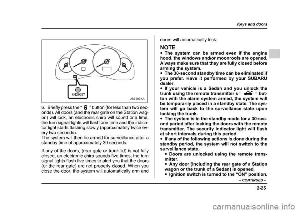
6. Briefly press the “ ” button (for less than two sec-
onds). All doors (and the rear gate on the Station wag-
on) will lock, an electronic chirp will sound one time,
the turn signal lights will flash one time and the indica-
tor light starts flashing slowly (approximately twice ev-
ery two seconds).
The system will then be armed for surveillance after a
standby time of approximately 30 seconds.
If any of the doors, (rear gate or trunk lid) is not fully
closed, an electronic chirp sounds five times, the turn
signal lights flash five times to alert you that the doors
(or the rear gate) are not properly closed. When you
close the door, the system will automatically arm and doors will automatically lock.
NOTE "
The system can be armed even if the engine
hood, the windows and/or moonroofs are opened.
Always make sure that they are fully closed before
arming the system. " The 30-second standby time can be eliminated if
you prefer. Have it performed by your SUBARU
dealer. " If your vehicle is a Sedan and you unlock the
trunk using the remote transmitter’s “ ” but-
ton with the alarm system armed, the system will
be temporarily placed in a standby state. The sys-
tem will go back to the surveillance state upon
locking the trunk. " The system is in the standby mode for a 30-sec-
ond period after locking the doors with the remote
transmitter. The security indicator light will flash
at short intervals during this period. " If any of the following actions is done during the
standby period, the system will not switch to the
surveillance state. "Doors are unlocked using the remote trans-
mitter." Any door (including the rear gate of a Station
wagon or the trunk of a Sedan) is opened. " Ignition switch is turned to the “ON” position.
UB7507KA
Page 151 of 627
2-26
Keys and doors
"
The alarm system is triggered when the ignition
switch is turned to the “ON” position during sur-
veillance. However, this does not occur if the vehi-
cle is equipped with an immobilizer and the key
used for turning the ignition switch has been reg-
istered. " If your vehicle is not equipped with an immobi-
lizer, the engine does not start even when the igni- tion switch is turned to the “START” position once
the alarm system has been triggered. ! Disarming the system
Briefly press the “ ” button (for less than two sec-
onds) on the remote transmitter. The driver’s door will
unlock, an electronic chirp will sound twice, the turn
signal lights will flash twice and the indicator light will
go off.
To unlock all other doors and the rear gate (Station
wagon), briefly press the “ ” button a second time.
NOTE
If the interval between the first and second press-
es of the “ ” button (for unlocking of all of the
doors and the rear gate) is extremely short, the
system may not respond.
Or the system can be disarmed by the following method, too. "
Insert the key in the door lock of the driver’s
door and turn it to the unlock position." Cycle the ignition switch from the “LOCK” to the
“ON” position three times within 5 seconds (only
vehicle without immobilizer). ! Emergency disarming
If you cannot disarm the system using the transmitter
(i.e. the transmitter is lost, broken or the transmitter
battery is too weak), you can disarm the system with-
out using the transmitter.
Vehicle with immobilizer
The system can be disarmed if you turn the ignition
switch from the “LOCK” to the “ON” position with a reg-
istered key.
Vehicle without immobilizer
1. Unlock the door with the key and then open the
door.
2. Insert the key into the ignition switch and cycle it
from the “LOCK” to the “ON” position three times with-
in 5 seconds .
All models
Insert the key in the door lock of the driver’s door and
turn it to the unlock position.
Page 172 of 627

3-1
3
Instruments and controls
Ignition switch .............................................. 3-3 LOCK .................................................................. 3-4
ACC .................................................................... 3-4
ON ....................................................................... 3-4
START ................................................................ 3-5
Key reminder chime .......................................... 3-6
Ignition switch light .......................................... 3-6
Hazard warning flasher ................................ 3-7
Meters and gauges (Turbo models) ............ 3-7 Combination meter illumination ...................... 3-7
Canceling the function for meter/gauge needle movement and combination meter
sequential illumination upon turning on the
ignition switch ................................................ 3-8
Speedometer ..................................................... 3-9
Odometer ........................................................... 3-9
Double trip meter .............................................. 3-10
Tachometer ........................................................ 3-11
Fuel gauge ......................................................... 3-11
Temperature gauge ........................................... 3-13
Meters and gauges (Non-turbo models) ..... 3-14 Combination meter illumination ...................... 3-14
Canceling the function for meter/gauge needle movement upon turning on the
ignition switch ................................................ 3-15
Speedometer ..................................................... 3-15
Odometer ........................................................... 3-16
Double trip meter .............................................. 3-16
Tachometer ........................................................ 3-17
Fuel gauge ......................................................... 3-18
Temperature gauge ........................................... 3-19 Warning and indicator lights ....................... 3-20
Seatbelt warning light and chime .................... 3-21
SRS airbag system warning light .................... 3-24
Front passenger’s frontal airbag ON and OFF indicators ........................................................ 3-24
CHECK ENGINE warning light/Malfunction indicator lamp ................................................. 3-25
Charge warning light ........................................ 3-26
Oil pressure warning light ............................... 3-26
AT OIL TEMPerature warning light (AT vehicles) ................................................... 3-27
Low tire pressure warning light (if equipped) .................................................... 3-27
ABS warning light ............................................. 3-28
Brake system warning light ............................. 3-29
Low fuel warning light ...................................... 3-30
Door open warning light .................................. 3-31
All-wheel drive warning light (AT vehicles) .... 3-31
Vehicle Dynamics Control operation indicator light (if equipped) ........................................... 3-31
Vehicle Dynamics Control warning light (if equipped)/Vehicle Dynamics Control OFF
indicator light (if equipped) ........................... 3-32
Security indicator light ..................................... 3-33
SPORT mode indicator light (AT vehicles) ..... 3-34
Selector lever position indicator (AT vehicles) ................................................... 3-34
Gear position indicator (AT vehicles) ............. 3-34
Turn signal indicator lights .............................. 3-34
High beam indicator light ................................. 3-35
Cruise control indicator light ........................... 3-35
Cruise control set indicator light .................... 3-35
Page 174 of 627
3-3
Instruments and controls
– CONTINUED –
Instruments and controlsIgnition switch
"Never turn the ignition switch to “LOCK”
while the vehicle is being driven or towed be-
cause that will lock the steering wheel, prevent-
ing steering control. And when the engine is
turned off, it takes a much greater effort than
usual to steer. " Before leaving the vehicle, always remove
the key from the ignition switch for safety and
never allow an unattended child to remains in
the vehicle. Failure to follow this procedure
could result in injury to a child or others. They
could operate the power windows, the sunroof
or other controls or even make the vehicle
move.
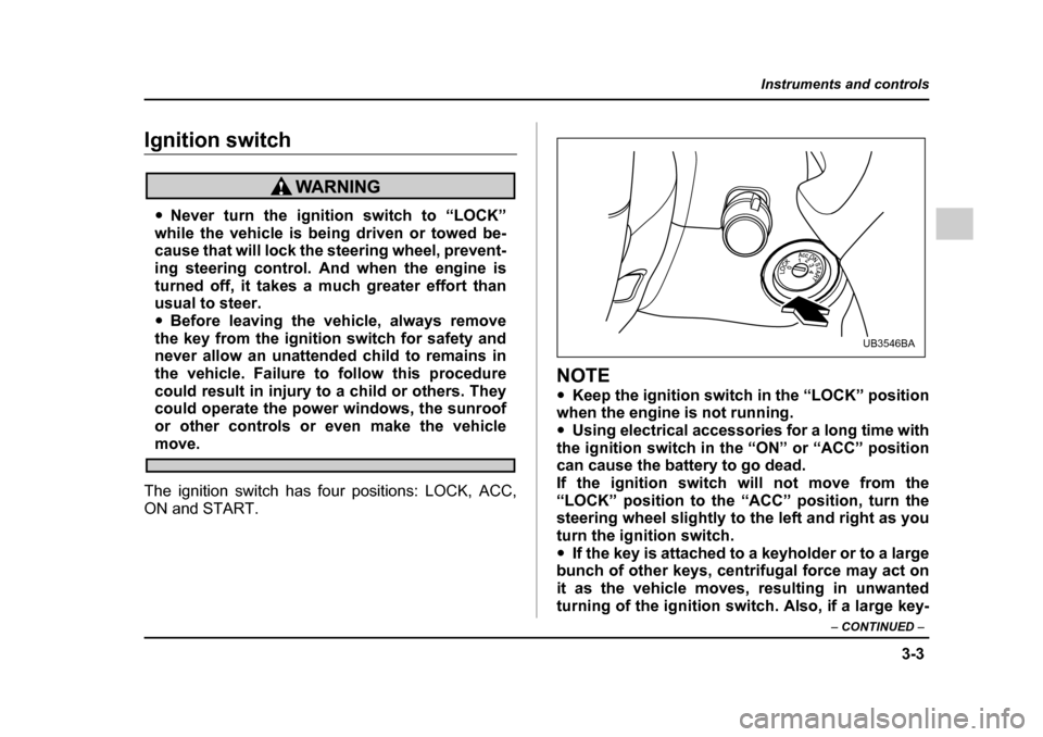
The ignition switch has four positions: LOCK, ACC,
ON and START.
NOTE " Keep the ignition switch in the “LOCK” position
when the engine is not running. " Using electrical accessories for a long time with
the ignition switch in the “ON” or “ACC” position
can cause the battery to go dead.
If the ignition switch will not move from the“LOCK” position to the “ACC” position, turn the
steering wheel slightly to the left and right as you turn the ignition switch." If the key is attached to a keyholder or to a large
bunch of other keys, centrifugal force may act on
it as the vehicle moves, resulting in unwanted
turning of the ignition switch. Also, if a large key-
UB3546BA
Page 175 of 627
3-4
Instruments and controls
holder is attached to the key, your knees or hands
may accidentally touch it in a way that turns the ig-
nition switch. !
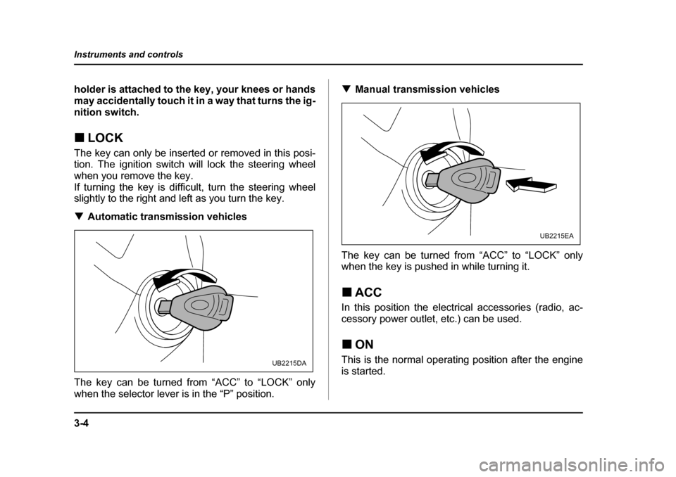
LOCK
The key can only be inserted or removed in this posi-
tion. The ignition switch will lock the steering wheel when you remove the key.
If turning the key is difficult, turn the steering wheel
slightly to the right and left as you turn the key. ! Automatic transmission vehicles
The key can be turned from “ACC” to “LOCK” only
when the selector lever is in the “P” position. !
Manual transmission vehicles
The key can be turned from “ACC” to “LOCK” only
when the key is pushed in while turning it. ! ACC
In this position the electrical accessories (radio, ac-
cessory power outlet, etc.) can be used. ! ON
This is the normal operating position after the engine
is started.
UB2215DA
UB2215EA
Page 176 of 627
3-5
Instruments and controls
– CONTINUED –
!START
Do not turn the ignition switch to the “START”
position while the engine is running.
The engine is started in this position. The starter
cranks the engine to start it. When the key is released
(after the engine has started), the key automatically
returns to the “ON” position. ! For vehicle with immobilizer
If your registered key fails to start the engine, pull out
the key once (the security indicator light will blink), and
then insert the key in the ignition switch and turn it to
the “START” position to start the engine again.
NOTE
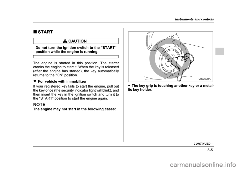
The engine may not start in the following cases: "
The key grip is touching another key or a metal-
lic key holder.
UB3209BA
Page 182 of 627
3-11
Instruments and controls
– CONTINUED –
NOTE
If the connection between the combination meter
and battery is broken for any reason such as vehi-
cle maintenance or fuse replacement, the data re-
corded on the trip meter will be lost. !Vehicle communication system fault indication
The vehicle communication system carries various
types of information (vehicle speed, running condi-
tions, etc.) to control modules. In the event of a fault in
this communication system, the trip meter will show“” .
If the trip meter shows “ ”, immediately contact
the nearest SUBARU dealer and have the vehicle
communication system inspected.
NOTE
If you press the trip knob while the trip meter is
showing “ ”, the trip meter indication will
appear for 10 seconds. ! Tachometer
The tachometer shows the engine speed in thousands
of revolutions per minute.
Do not operate the engine with the pointer of
the tachometer in the red zone. In this range,
fuel injection will be cut by the engine control
module to protect the engine from overrevving.
The engine will resume running normally after
the engine speed is reduced below the red
zone.
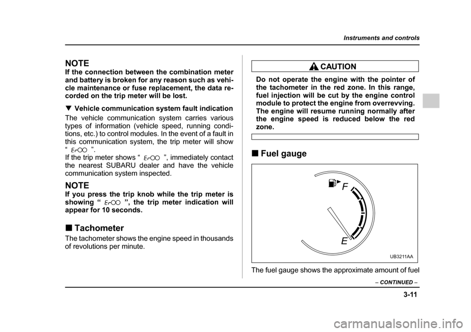
! Fuel gauge
The fuel gauge shows the approximate amount of fuel
UB3211AA
Page 184 of 627
3-13
Instruments and controls
– CONTINUED –
NOTE
You will see the “ ” sign in the fuel gauge
meter.
This indicates that the fuel filler door (lid) is locat-
ed on the right side of the vehicle. !Low fuel warning light
The low fuel warning light comes on when the tank is
nearly empty [About 2.6 US gal (10 liters, 2.2 lmp gal)].
It only operates when the ignition switch is in the “ON” position.
NOTE
This light does not go out unless the tank is re- plenished up to an internal fuel quantity of about
4.0 US gal (15 liters, 3.3 lmp gal). !
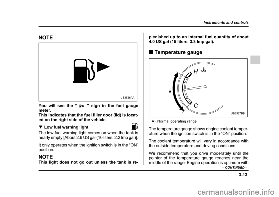
Temperature gauge
A) Normal operating range
The temperature gauge shows engine coolant temper-
ature when the ignition switch is in the “ON” position.
The coolant temperature will vary in accordance with
the outside temperature and driving conditions.
We recommend that you drive moderately until the
pointer of the temperature gauge reaches near the
middle of the range. Engine operation is optimum with
UB3526AA
A
UB3527BB
Page 185 of 627
3-14
Instruments and controls
the engine coolant at this temperature range and high
revving operation when the engine is not warmed up
enough should be avoided.
If the pointer exceeds the normal operating
range, safely stop the vehicle as soon as possi-
ble.
See the “In case of emergency” in chapter 9.
Meters and gauges (Non-turbo mod-
els) !
Combination meter illumination
When the ignition switch is turned to the “ON” position,
the various parts of the combination meter are illumi-
nated in the following sequence:
1. Combination meter dials light up.
2. Meter needles and gauge needles each show MAXposition.
3. Meter needles and gauge needles each show MIN position.
4. Regular illumination (for driving) begins.