turn signal SUBARU LEGACY 2008 4.G User Guide
[x] Cancel search | Manufacturer: SUBARU, Model Year: 2008, Model line: LEGACY, Model: SUBARU LEGACY 2008 4.GPages: 444, PDF Size: 14.1 MB
Page 121 of 444
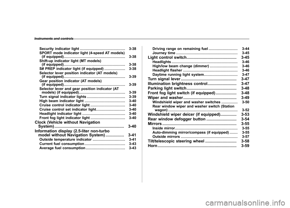
Instruments and controlsSecurity indicator light ....................................... 3-38
SPORT mode indicator light (4-speed AT models) (if equipped) ..................................................... 3-38
Shift-up indicator light (MT models) (if equipped) ..................................................... 3-38
S# PREP indicator light (if equipped) .................. 3-38
Selector lever position indicator (AT models) (if equipped) ..................................................... 3-39
Gear position indicator (AT models) (if equipped) ..................................................... 3-39
Selector lever and gear position indicator (AT models) (if equipped) ........................................ 3-39
Turn signal indicator lights ................................. 3-39
High beam indicator light ................................... 3-40
Cruise control indicator light .............................. 3-40
Cruise control set indicator light ......................... 3-40
Headlight indicator light ..................................... 3-40
Front fog light indicator light .............................. 3-40
Clock (Vehicle without Navigation System) ............................................................ 3-40
Information display (2.5-liter non-turbo model without Navigation System) ................ 3-41
Outside temperature indicator ............................ 3-41
Current fuel consumption ................................... 3-43
Average fuel consumption .................................. 3-43 Driving range on remaining fuel
......................... 3-44
Journey time ..................................................... 3-45
Light control switch ........................................... 3-45
Headlights ......................................................... 3-46
High/low beam change (dimmer) ... ..................... 3-46
Headlight flasher ............................................... 3-46
Daytime running light system ............................. 3-47
Turn signal lever ................................................ 3-47
Illumination brightness control ......................... 3-47
Parking light switch ........................................... 3-48
Front fog light switch (if equipped) .................. 3-48
Wiper and washer .............................................. 3-49
Windshield wiper and washer switches .............. 3-50
Rear window wiper and washer switch (Station wagon) ............................................................ 3-52
Windshield wiper deicer (if equipped) .............. 3-53
Rear window defogger button .......................... 3-54
Mirrors ................................................................ 3-55
Inside mirror ...................................................... 3-55
Auto-dimming mirror/compass (if equipped) ....... 3-55
Outside mirrors ................................................. 3-57
Tilt/telescopic steering wheel ........................... 3-58
Horn .................................................................... 3-59
Page 124 of 444

&Key reminder chime
The reminder chime sounds when the driver ’s door opens and the key is in the
“ LOCK ”or “Acc ”positions. The chime
stops when the key is removed from the
ignition switch. & Ignition switch light
For easy access to the ignition switch in
the dark, the ignition switch light comes on
when any of the doors are opened. The
light remains on for a several seconds and
gradually goes out after all doors are
closed or if the key is inserted in the
ignition switch. Hazard warning flasher
The hazard warning flasher is used to
warn other drivers when you have to park
your vehicle under emergency conditions.
The hazard warning flasher works with the
ignition switch in any position.
To turn on the hazard warning flasher,
push the hazard warning button on the
instrument panel. To turn off the flasher,
push the button again. NOTE
When the hazard warning flasher is on,
the turn signals do not work.Meters and gauges (Vehicle
with SI-DRIVE) NOTE
Liquid-crystal displays are used in
some of the meters and gauges in the
combination meter. You will find their
indications hard to see if you wear
polarized glasses. &
Combination meter illumina- tion
When the ignition switch is turned to the “ ON ”position, the various parts of the
combination meter are illuminated in the
following sequence:
1. Meter needles, gauge needles and
multi-information display light up.
2. Meter needles and gauge needles
each show MAX position.
3. Meter needles and gauge needles
each show MIN position.
4. Dials in meters and gauges light up.
5. Regular illumination (for driving) be- gins.
NOTE
The above sequence of operations may
not take place if you quickly turn the Instruments and controls
3-5
– CONTINUED –
Page 152 of 444
properly. If there is no problem and all tires
are properly inflated, the light will go out.
Each tire, including the spare (if provided),
should be checked monthly when cold
and inflated to the inflation pressure
recommended by the vehicle manufac-
turer on the vehicle placard or tire inflation
pressure label. (If your vehicle has tires of
a different size than the size indicated on
the vehicle placard or tire inflation pres-
sure label, you should determine the
proper inflation pressure for those tires.)
As an added safety feature, your vehicle
has been equipped with a tire pressure
monitoring system (TPMS) that illuminates
a low tire pressure telltale when one or
more of your tires is significantly under-
inflated. Accordingly, when the low tire
pressure telltale illuminates, you should
stop and check your tires as soon as
possible, and inflate them to the proper
pressure. Driving on a significantly under-
inflated tire causes the tire to overheat and
can lead to tire failure. Under-inflation also
reduces fuel efficiency and tire tread life,
and may affect the vehicle’s handling and
stopping ability.
Please note that the TPMS is not a
substitute for proper tire maintenance,
and it is the driver ’s responsibility to
maintain correct tire pressure, even if
under-inflation has not reached the level to trigger illumination of the TPMS low tire
pressure telltale.
Your vehicle has also been equipped with
a TPMS malfunction indicator to indicate
when the system is not operating properly.
The TPMS malfunction indicator is com-
bined with the low tire pressure telltale.
When the system detects a malfunction,
the telltale will flash for approximately one
minute and then remain continuously
illuminated. This sequence will continue
upon subsequent vehicle start-ups as long
as the malfunction exists. When the
malfunction indicator is illuminated, the
system may not be able to detect or signal
low tire pressure as intended. TPMS
malfunctions may occur for a variety of
reasons, including the installation of re-
placement or alternate tires or wheels on
the vehicle that prevent the TPMS from
functioning properly. Always check the
TPMS malfunction telltale after replacing
one or more tires or wheels on your
vehicle to ensure that the replacement or
alternate tires and wheels allow the TPMS
to continue to function properly.
Should the warning light illuminate stea-
dily after blinking for approximately one
minute, have the system inspected by
your nearest SUBARU dealer as soon aspossible.WARNING
If this light does not come on briefly
after the ignition switch is turned ON
or the light illuminates steadily after
blinking for approximately one min-
ute, you should have your Tire
Pressure Monitoring System
checked at a SUBARU dealer as
soon as possible.
If this light comes on while driving,
never brake suddenly and keep
driving straight ahead while gradu-
ally reducing speed. Then slowly
pull off the road to a safe place.
Otherwise an accident involving
serious vehicle damage and serious
personal injury could occur.
If this light still comes on while
driving after adjusting the tire pres-
sure, a tire may have significant
damage and a fast leak that causes
the tire to lose air rapidly. If you have
a flat tire, replace it with a spare tire
as soon as possible.
When a spare tire is mounted or a
wheel rim is replaced without the
original pressure sensor/transmitter
being transferred, the Low tire pres-
sure warning light will illuminates
steadily after blinking for approxi-
mately one minute. This indicates Instruments and controls
3-33
– CONTINUED –
Page 158 of 444
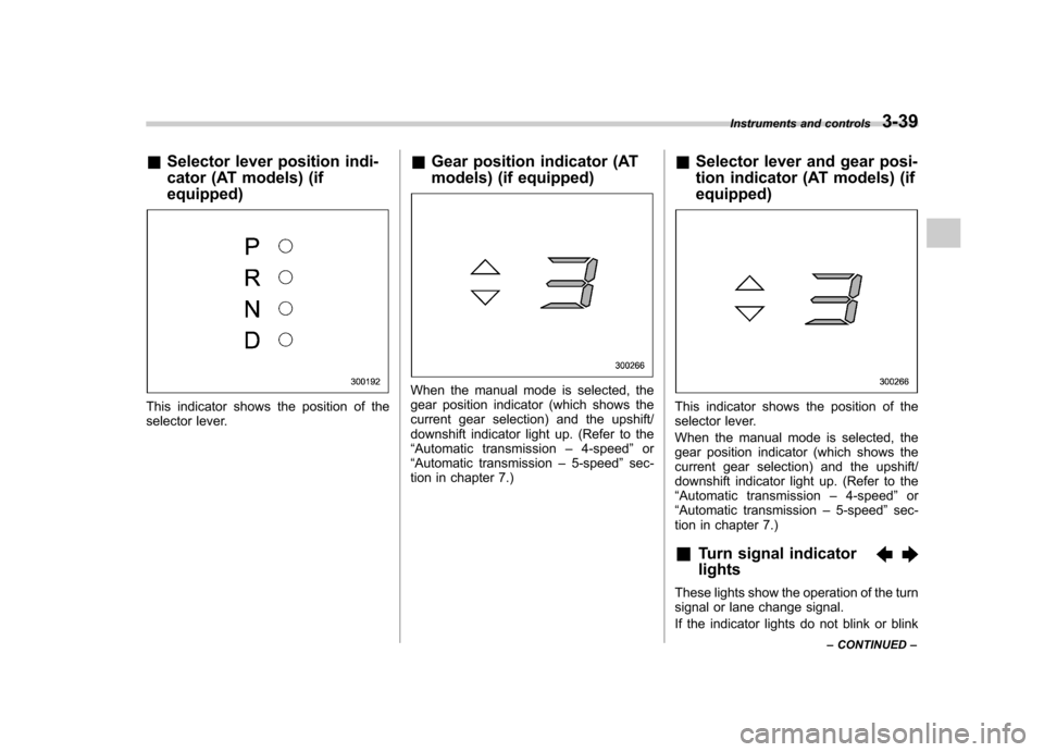
&Selector lever position indi-
cator (AT models) (if equipped)
This indicator shows the position of the
selector lever. &
Gear position indicator (AT
models) (if equipped)
When the manual mode is selected, the
gear position indicator (which shows the
current gear selection) and the upshift/
downshift indicator light up. (Refer to the“Automatic transmission –4-speed ”or
“ Automatic transmission –5-speed ”sec-
tion in chapter 7.) &
Selector lever and gear posi-
tion indicator (AT models) (if equipped)
This indicator shows the position of the
selector lever.
When the manual mode is selected, the
gear position indicator (which shows the
current gear selection) and the upshift/
downshift indicator light up. (Refer to the“Automatic transmission –4-speed ”or
“ Automatic transmission –5-speed ”sec-
tion in chapter 7.)
& Turn signal indicator lights
These lights show the operation of the turn
signal or lane change signal.
If the indicator lights do not blink or blink Instruments and controls
3-39
– CONTINUED –
Page 159 of 444

3-40Instruments and controls
rapidly, the turn signal bulb may be burned
out. Replace the bulb as soon as possible.
Refer to the “Replacing bulbs ”section in
chapter 11.
& High beam indicator light
This light shows that the headlights are in
the high beam mode.
This indicator light also comes on when
the headlight flasher is operated. &Cruise control indica-
tor light
The cruise control indicator light comes on
when the ignition switch is turned to the“ON ”position and goes out after approxi-
mately 3 seconds.
This light comes on when the “CRUISE ”
main switch is pressed. NOTE . If you move the cruise control lever
or press the main switch button while
turning the ignition switch “ON ”, the
cruise control function is deactivated
and the “CRUISE ”indicator light
flashes. To reactivate the cruise control
function, turn the ignition switch back
to the “Acc ”or “LOCK ”position, and
then turn it again to the “ON ”position. .
If this indicator light and the CHECK
ENGINE warning light/malfunction in-
dicator lamp flash simultaneously dur-
ing driving, have the vehicle checked
by your nearest SUBARU dealer. & Cruise control set in-
dicator light
The cruise control set indicator light
comes on when the ignition switch is
turned to the “ON ”position and goes out
after approximately 3 seconds.
This light comes on when vehicle speed
has been set.
& Headlight indicator light
This indicator light comes on when the
light switch is turned to the “”position
(to turn on the parking lights) or to the “
” position (to turn on the headlights).
& Front fog light indicator light
This indicator light is on while the front fog
lights are on. Clock (Vehicle without Navi-
gation System) NOTE .
If your vehicle is a 2.5-liter non-turbo
model equipped with a navigation sys-
tem, refer to the separate “Operating
Instructions for Monitor System ”.
. If your vehicle is a turbo model or a
3.0-liter model equipped with a naviga-
tion system, refer to the “Clock (Vehicle
with Navigation System) ”in the multi-
information display (vehicle with SI-
DRIVE) section in this chapter.
The clock shows the time while the
ignition switch is in the “Acc ”or “ON ”
position.
Page 165 of 444
3-46Instruments and controls
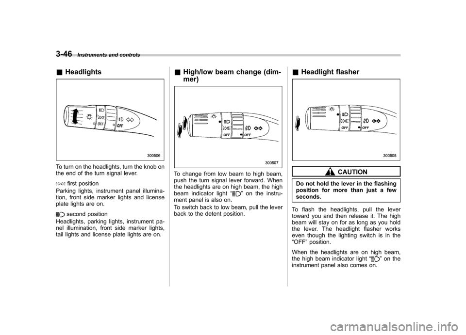
&Headlights
To turn on the headlights, turn the knob on
the end of the turn signal lever.
first position
Parking lights, instrument panel illumina-
tion, front side marker lights and license
plate lights are on.
second position
Headlights, parking lights, instrument pa-
nel illumination, front side marker lights,
tail lights and license plate lights are on. &
High/low beam change (dim- mer)
To change from low beam to high beam,
push the turn signal lever forward. When
the headlights are on high beam, the high
beam indicator light “
”on the instru-
ment panel is also on.
To switch back to low beam, pull the lever
back to the detent position. &
Headlight flasher
CAUTION
Do not hold the lever in the flashing
position for more than just a fewseconds.
To flash the headlights, pull the lever
toward you and then release it. The high
beam will stay on for as long as you hold
the lever. The headlight flasher works
even though the lighting switch is in the“ OFF ”position.
When the headlights are on high beam,
the high beam indicator light “
”on the
instrument panel also comes on.
Page 166 of 444
&Daytime running light system
WARNING
The brightness of the illumination of
the high beam headlights is reduced
by the daytime running light system.
The light switch must always be
turned to the “
”position when it
is dark outside.
The high beam headlights will automati-
cally come on at reduced brightness when
the engine has started, under the followingconditions: . The parking brake is fully released.
. The light switch is in the “OFF ”or “
”
position.
NOTE
When the light switch is in the “
”
position, the front side marker lights,
parking lights and license plate lights
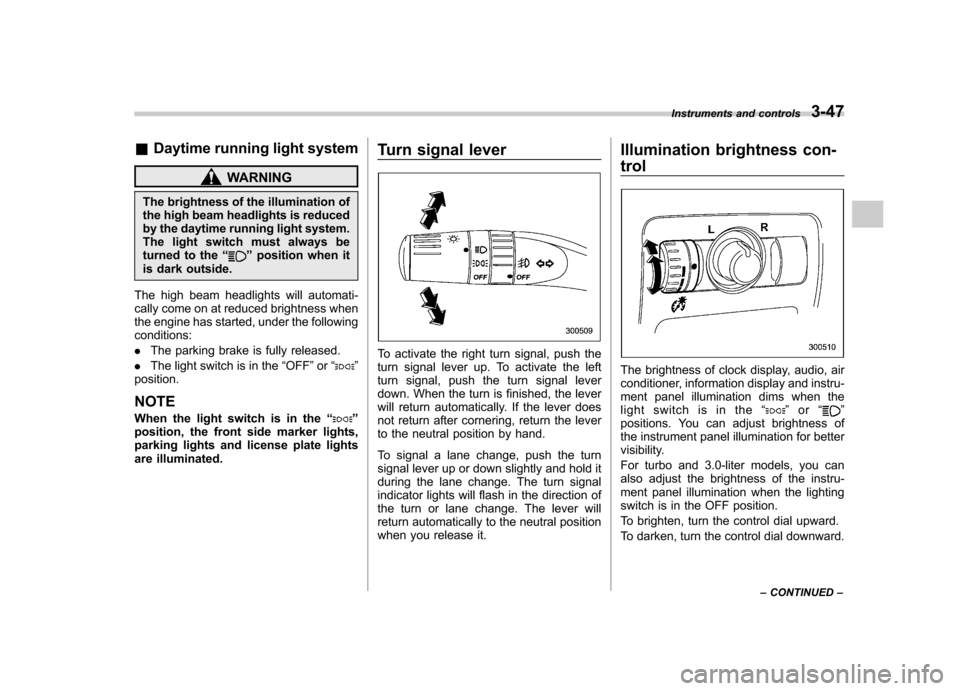
are illuminated. Turn signal lever
To activate the right turn signal, push the
turn signal lever up. To activate the left
turn signal, push the turn signal lever
down. When the turn is finished, the lever
will return automatically. If the lever does
not return after cornering, return the lever
to the neutral position by hand.
To signal a lane change, push the turn
signal lever up or down slightly and hold it
during the lane change. The turn signal
indicator lights will flash in the direction of
the turn or lane change. The lever will
return automatically to the neutral position
when you release it.Illumination brightness con- trol
The brightness of clock display, audio, air
conditioner, information display and instru-
ment panel illumination dims when the
light switch is in the
“
”or “”
positions. You can adjust brightness of
the instrument panel illumination for better
visibility.
For turbo and 3.0-liter models, you can
also adjust the brightness of the instru-
ment panel illumination when the lighting
switch is in the OFF position.
To brighten, turn the control dial upward.
To darken, turn the control dial downward. Instruments and controls
3-47
– CONTINUED –
Page 167 of 444
3-48Instruments and controls
NOTE
When the control dial is turned fully
upward, the illumination brightness
becomes the maximum and the auto-
matic dimming function does not work
at all. Parking light switch
The parking light switch operates regard-
less of the ignition switch position.
By pushing the front end of this switch,
following lights will come on. –
Parking lights
– Front and rear side marker lights
– Tail lights
– License plate lights
To turn off, push the rear end of the
parking light switch.
Avoid leaving these lights on for a long
time because that will run down the
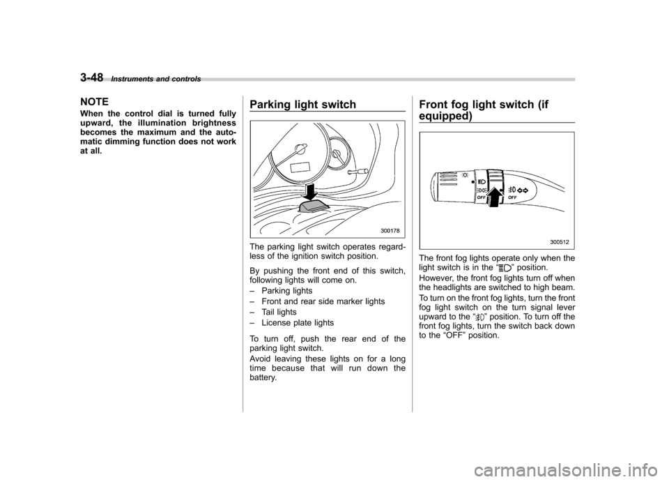
battery. Front fog light switch (if
equipped)
The front fog lights operate only when the
light switch is in the
“”position.
However, the front fog lights turn off when
the headlights are switched to high beam.
To turn on the front fog lights, turn the front
fog light switch on the turn signal lever
upward to the “
”position. To turn off the
front fog lights, turn the switch back down
to the “OFF ”position.
Page 268 of 444
selector lever to the“P ” position at this
time. ! Selector lever release button
If you inadvertently have turned the igni-
tion switch to the “LOCK ”position with the
selector lever in the “N ”position, proceed
as follows. By referring to the “Shift lock
release ”section in this chapter, remove
the shift lock release cover. Then, with the
screwdriver inserted into the hole, move
the selector lever to the “P ”position. If the
selector lever reverse inhibiting function
fails, have the vehicle inspected by the
nearest SUBARU dealer. &
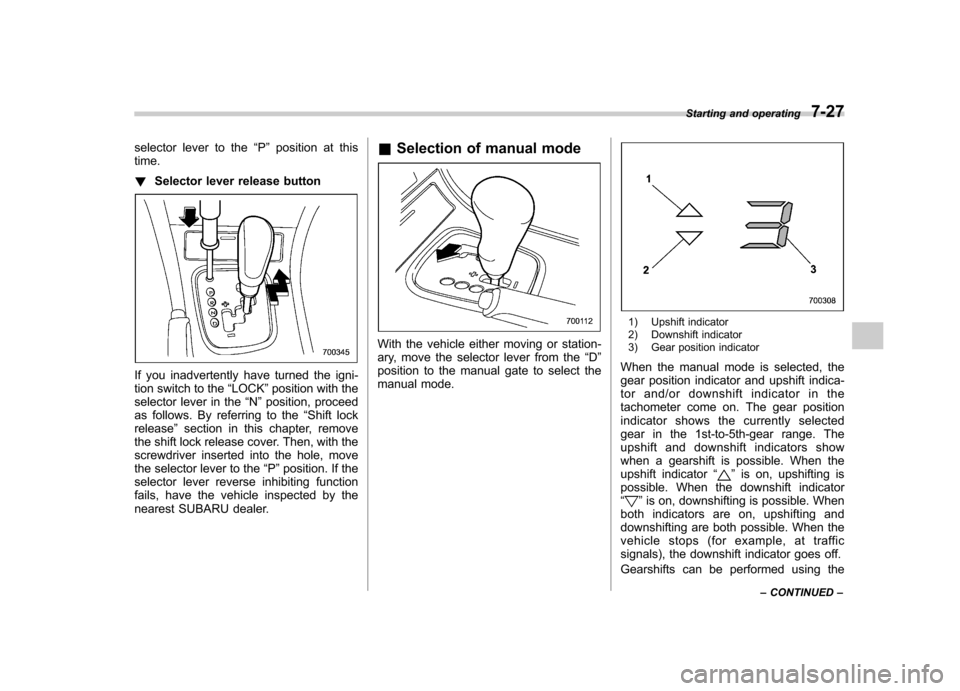
Selection of manual mode
With the vehicle either moving or station-
ary, move the selector lever from the “D ”
position to the manual gate to select the
manual mode.
1) Upshift indicator
2) Downshift indicator
3) Gear position indicator
When the manual mode is selected, the
gear position indicator and upshift indica-
tor and/or downshift indicator in the
tachometer come on. The gear position
indicator shows the currently selected
gear in the 1st-to-5th-gear range. The
upshift and downshift indicators show
when a gearshift is possible. When the
upshift indicator “
”is on, upshifting is
possible. When the downshift indicator “
” is on, downshifting is possible. When
both indicators are on, upshifting and
downshifting are both possible. When the
vehicle stops (for example, at traffic
signals), the downshift indicator goes off.
Gearshifts can be performed using the Starting and operating
7-27
– CONTINUED –
Page 312 of 444
WARNING
Do not connect safety chains to part
of the vehicle other than the safety
chain hooks.
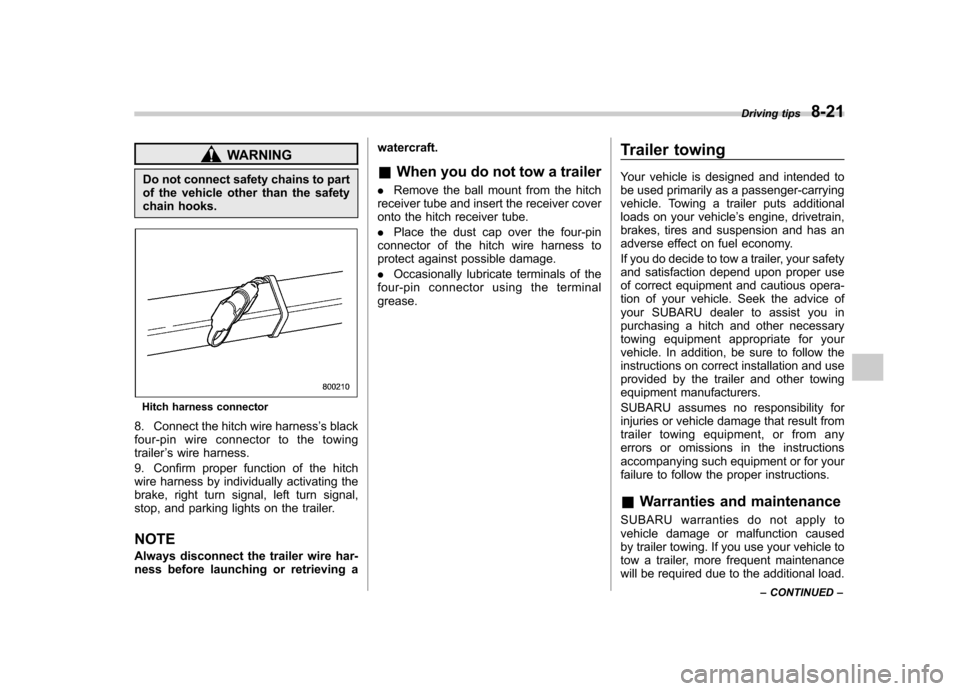
Hitch harness connector
8. Connect the hitch wire harness ’s black
four-pin wire connector to the towing trailer ’s wire harness.
9. Confirm proper function of the hitch
wire harness by individually activating the
brake, right turn signal, left turn signal,
stop, and parking lights on the trailer. NOTE
Always disconnect the trailer wire har-
ness before launching or retrieving a watercraft.
& When you do not tow a trailer
. Remove the ball mount from the hitch
receiver tube and insert the receiver cover
onto the hitch receiver tube. . Place the dust cap over the four-pin
connector of the hitch wire harness to
protect against possible damage. . Occasionally lubricate terminals of the
four-pin connector using the terminal grease. Trailer towing
Your vehicle is designed and intended to
be used primarily as a passenger-carrying
vehicle. Towing a trailer puts additional
loads on your vehicle
’s engine, drivetrain,
brakes, tires and suspension and has an
adverse effect on fuel economy.
If you do decide to tow a trailer, your safety
and satisfaction depend upon proper use
of correct equipment and cautious opera-
tion of your vehicle. Seek the advice of
your SUBARU dealer to assist you in
purchasing a hitch and other necessary
towing equipment appropriate for your
vehicle. In addition, be sure to follow the
instructions on correct installation and use
provided by the trailer and other towing
equipment manufacturers.
SUBARU assumes no responsibility for
injuries or vehicle damage that result from
trailer towing equipment, or from any
errors or omissions in the instructions
accompanying such equipment or for your
failure to follow the proper instructions.
& Warranties and maintenance
SUBARU warranties do not apply to
vehicle damage or malfunction caused
by trailer towing. If you use your vehicle to
tow a trailer, more frequent maintenance
will be required due to the additional load. Driving tips
8-21
– CONTINUED –