interior lights SUBARU LEGACY 2009 5.G Owners Manual
[x] Cancel search | Manufacturer: SUBARU, Model Year: 2009, Model line: LEGACY, Model: SUBARU LEGACY 2009 5.GPages: 447, PDF Size: 14.26 MB
Page 98 of 447

2-6Keys and doors
&Locking and unlocking from
the inside
WARNING
Keep all doors locked when you
drive, especially when small chil-
dren are in your vehicle.
Along with the proper use of seat-
belts and child restraints, locking
the doors reduces the chance of
being thrown out of the vehicle in anaccident.
It also helps prevent passengers
from falling out if a door is acciden-
tally opened, and intruders from
unexpectedly opening doors and
entering your vehicle.
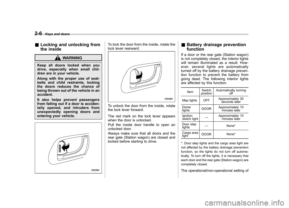
To lock the door from the inside, rotate the
lock lever rearward.
To unlock the door from the inside, rotate
the lock lever forward.
The red mark on the lock lever appears
when the door is unlocked.
Pull the inside door handle to open an
unlocked door.
Always make sure that all doors and the
rear gate (Station wagon) are closed and
locked before starting to drive. &
Battery drainage prevention function
If a door or the rear gate (Station wagon)
is not completely closed, the interior lights
will remain illuminated as a result. How-
ever, several lights are automatically
turned off by the battery drainage preven-
tion function to prevent the battery from
going dead. The following interior lights
are affected by this function.
Item Switch
position Automatically turning
off
Map lights OFF Approximately 30
seconds later
Dome lights DOOR
Approximately 10
minutes later
Ignition
switch light —
Approximately 10
minutes later
Door steplights —
None*
Cargo arealight DOOR
None*
*: Door step lights and the cargo area light are
not affected by the battery drainage prevention
function, so the lights do not turn off automa-
tically. To turn off the lights, it is necessary that
each door and the rear gate (Station wagon) are
completely closed.
The operational/non-operational setting of
Page 226 of 447

Map light
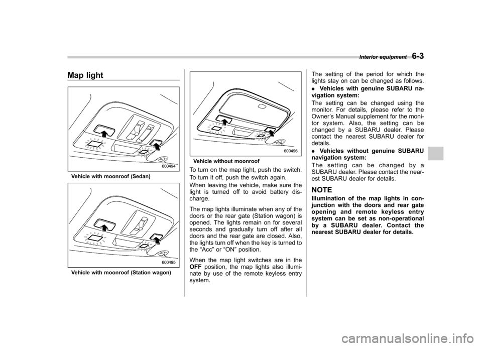
Vehicle with moonroof (Sedan)
Vehicle with moonroof (Station wagon)
Vehicle without moonroof
To turn on the map light, push the switch.
To turn it off, push the switch again.
When leaving the vehicle, make sure the
light is turned off to avoid battery dis-charge.
The map lights illuminate when any of the
doors or the rear gate (Station wagon) is
opened. The lights remain on for several
seconds and gradually turn off after all
doors and the rear gate are closed. Also,
the lights turn off when the key is turned tothe “Acc ”or “ON ”position.
When the map light switches are in theOFF position, the map lights also illumi-
nate by use of the remote keyless entrysystem. The setting of the period for which the
lights stay on can be changed as follows. .
Vehicles with genuine SUBARU na-
vigation system:
The setting can be changed using the
monitor. For details, please refer to theOwner ’s Manual supplement for the moni-
tor system. Also, the setting can be
changed by a SUBARU dealer. Please
contact the nearest SUBARU dealer fordetails. . Vehicles without genuine SUBARU
navigation system:
The setting can be changed by a
SUBARU dealer. Please contact the near-
est SUBARU dealer for details.
NOTE
Illumination of the map lights in con-
junction with the doors and rear gate
opening and remote keyless entry
system can be set as non-operational
by a SUBARU dealer. Contact the
nearest SUBARU dealer for details. Interior equipment
6-3
Page 259 of 447

transmitter within a few seconds immedi-
ately following remote engine start shut-down. &Pre-heating or pre-cooling
the interior of the vehicle
Before exiting the vehicle, set the tem-
perature controls to the desired setting
and operation. After the system starts the
vehicle, the heater or air-conditioning will
activate and heat or cool the interior to
your setting. & Service mode
In service mode, the remote start function
is temporarily disabled to prevent the
system from unexpectedly starting the
engine while being serviced. ! To engage the service mode
Turn the ignition switch to the “ON ”
position, depress and hold the brake pedal
then, press and release the “
”button on
the remote control transmitter three times.
The system will pause for 1 second and
then flash the parking lights and honk the
horn three times indicating that the system
is in service mode. When attempting to
activate the remote start system while in
service mode, the parking lights will flash
and the horn will honk two times and will
not start. !
To disengage the service mode
Turn the ignition switch to the “ON ”
position, depress and hold the brake
pedal, then press and release the “
”
button on the remote control transmitter
three times. The system will pause for 1
second and flash the parking lights 1 time
indicating that the system has exited
service mode. NOTE
When taking your vehicle in for service,
it is recommended that you inform the
service personnel that your vehicle is
equipped with a remote control startsystem. & Remote transmitter program-
ming and programmable fea-
ture option
New transmitters can be programmed to
the engine starter system in the event that
remote transmitters are lost, stolen or
damaged. The remote engine start system
also has one programmable feature that
can be adjusted for user preference.
The remote engine starter system can be
programmed to either make an audible
horn chirp upon remote start activation or
not. Remote transmitter programming and
feature programming can be adjusted
using the following procedure. 1. Open the driver
’s door (the driver ’s
door must remain opened throughout the
entire process).
2. Insert the key into the vehicle ’s ignition
switch and turn to the “ON ”position.
3. Locate the small black programming
button behind the fuse box cover, on the
driver ’s side left under the dashboard
panel.
4. Press and hold the black programming
button for 10 to 15 seconds. The horn will
honk and the parking lights will flash three
times to indicate that the system has
entered programming mode. At this point
you can perform either action (Step 5 or
Step 6).
5. To program a remote transmitter:
press and release the “
”button on each
transmitter. The horn will honk and the
parking lights will flash one time to indicate
a successful transmitter learn each timethe “
”button is pressed. You can
program up to eight transmitters.
6. To toggle the Horn Confirmation chirps
ON/OFF: press and release the brake to
toggle the feature. The horn will chirp and
the parking lights will flash one time to
indicate Confirmation Horn Chirps are“ OFF ”. The horn will honk and the parking
lights will flash 2 times to indicate Con-
firmation Horn Chirps are “ON ”. Pressing
the brake pedal repeatedly will toggle the Starting and operating
7-13
– CONTINUED –
Page 439 of 447

Front turn signal/Parking and front side marker ............. 11-53
Fuel ........................................................................... 7-3
Economy hints ......................................................... 8-2
Filler lid and cap ...................................................... 7-5
Gauge ............................................................ 3-6, 3-26
Requirements .......................................................... 7-3
Fuses ...................................................................... 11-47
Fuses and circuits ...................................................... 12-6
G
GAWR (Gross Axle Weight Rating) .............................. 8-15
Gear position indicator ................................................ 3-39
Glove box ................................................................... 6-5
GVWR (Gross Vehicle Weight Rating) .......................... 8-15
H
Hazard warning flasher ........................................... 3-5, 9-2
Head restraint adjustment Front seat ............................................................... 1-7
Rearseat ............................................................... 1-10
Headlight Flasher ................................................................. 3-47
Indicator light ......................................................... 3-40
Headlights ........................................................ 3-46, 11-51
Heater operation (manual climate control system) ............ 4-5
High beam indicator light ............................................ 3-40
High mount stop light ................................................. 11-59
High/low beam change (dimmer) .................................. 3-46
Horn ......................................................................... 3-59
Hose and connections ............................................... 11-14 I
Ignition switch
............................................................. 3-3
Light ...................................................................... 3-5
Illumination brightness control ...................................... 3-48
Immobilizer ................................................................. 2-3
Indicator light (security indicator light) ................. 2-4, 3-38
Indicator light
Cruise control ................................................ 3-40, 7-49
Cruise control set ........................................... 3-40, 7-50
Front fog light ......................................................... 3-40
Headlight ............................................................... 3-40
High beam ............................................................. 3-40
Immobilizer ............................................................. 2-4
S# PREP .............................................................. 3-39
Security .......................................................... 2-4, 3-38
Selector lever position ............................................. 3-39
Selector lever/Gear position ..................................... 3-40
Shift-up ................................................................. 3-38
SPORT mode ........................................................ 3-38
Traction control system OFF .................................... 3-37
Turn signal ............................................................ 3-40
Vehicle Dynamics Control OFF ......................... 3-38, 7-40
Vehicle Dynamics Control operation .................. 3-37, 7-40
Information display ...................................................... 3-41
Inside mirror .............................................................. 3-56
Interior lights ............................................................... 6-2
Internal trunk lid release handle .................................... 2-25
JJack. ......................................................................... 9-18
Jack handle ............................................................... 9-19 Index
14-5