cooling SUBARU LEGACY 2010 5.G Owners Manual
[x] Cancel search | Manufacturer: SUBARU, Model Year: 2010, Model line: LEGACY, Model: SUBARU LEGACY 2010 5.GPages: 448, PDF Size: 7.36 MB
Page 159 of 448

Ventilator.............................................................. 4-2
Air flow selection ................................................ 4-2
Ventilators ........................................................... 4-3
Manual climate control system (if equipped) ..................................................... 4-4
Control panel ...................................................... 4-4
Heater operation ................................................. 4-6
Air conditioner operation ..................................... 4-7
Automatic climate control system (if equipped) ..................................................... 4-8
Control panel ...................................................... 4-9
Temperature sensors .......................................... 4-13
Operating tips for heater and air conditioner ....................................................... 4-14
Cleaning ventilator grille ..................................... 4-14 Efficient cooling after parking in direct
sunlight ........................................................... 4-14
Lubrication oil circulation in the refrigerant circuit .............................................................. 4-14
Checking air conditioning system before summer season ............................................................ 4-14
Cooling and dehumidifying in high humidity and low temperature weather condition ................... 4-14
Air conditioner compressor shut-off when engine is heavily loaded .............................................. 4-14
Refrigerant for your climate control system ... ..... 4-14
Air filtration system ........................................... 4-15
Replacing an air filter ......................................... 4-15Climate control
4
Page 165 of 448
3. Turn the temperature control dial all
the way to the right.
4. Set the fan speed control dial to the
highest speed. !Heating and defrosting
To direct warm air toward the floor and the windshield:
1. Set the air inlet selection button to the
OFF position.
2. Press the “
”button.
3. Set the temperature control dial to the
most comfortable level.
4. Set the fan speed control dial to the
desired speed. ! Heating
To direct warm air toward the floor:
1. Set the air inlet selection button to the
OFF position.
2. Press the “
”button.
3. Set the temperature control dial to the
most comfortable level.
4. Set the fan speed control dial to the
desired speed. ! Bi-level heating
This setting allows you to direct air of
different temperatures from the instrument
panel and foot outlets. The air from the foot outlets is slightly warmer than from
the instrument panel outlets.
1. Set the air inlet selection button to the
OFF position.
2. Press the
“
”button.
3. Set the temperature control dial to the
desired temperature level.
4. Set the fan speed control dial to the
desired speed.
Setting the temperature control dial fully
turned to the red area or blue area
decreases the temperature difference
between the air from the instrument panel
outlets and the air from the foot outlets. ! Ventilation
To force outside air through the instrument
panel outlets:
1. Set the air inlet selection button to the
OFF position.
2. Press the “
”button.
3. Set the temperature control dial all the
way left.
4. Set the fan speed control dial to the
desired speed.
When driving on a dusty road, set the air
inlet control button to the ON position.
WARNING
Continued operation in the ON posi-
tion may fog up the windows. Switch
to the OFF position as soon as the
outside dusty condition clears.
& Air conditioner operation
! Cooling or dehumidifying
For cooling and dehumidification of the
passenger compartment, air flows through
the instrument panel outlets:
1. Set the air inlet selection button to the
OFF position.
2. Press the “
”button.
3. Set the air conditioner button to the “ ON ”position.
4. Set the temperature control dial to the
blue side.
5. Set the fan speed control dial at the
desired speed. ! Defrosting or defogging
To direct warm air to the windshield and
front door windows:
1. Press the “
”button.
2. Set the temperature control dial to the
red side.
3. Set the fan speed control dial at the
highest speed. Climate control
4-7
– CONTINUED –
Page 166 of 448

4-8Climate control
NOTE
When the “
”button or “”button is
pressed the air conditioner compres-
sor automatically operates to quickly
defog the windshield. However the
indicator on the air conditioner button
will not illuminate. At the same time,
the air inlet selection is automatically
set to “outside air ”mode. Automatic climate control
system (if equipped) NOTE .
Operate the automatic climate con-
trol system when the engine is running. . The blower fan rotates at a low
speed when the engine coolant tem-
perature is low.
For efficient defogging or dehumidify-
ing in cold weather, press the “A/C ”
button.. Even when cooling is not necessary,
setting the temperature much lower
than the current outlet air temperature
turns on the air conditioner compres-
sor automatically and the “A/C ”indi-
cator light on the control panel illumi-nates.
The automatic climate control system
automatically controls outlet air tempera-
ture, fan speed, air flow distribution air-
inlet control, and air conditioner compres-
sor operation. It activates when the fan
speed control button or the “AUTO ”button
is pressed, and is used to maintain a
constant, comfortable climate within the
passenger compartment. If you press the
defroster button while the automatic cli-
mate control system is deactivated, only
the defroster function will be activated. The temperature can be set within a range
of 61 to 89
8F (18.5 to 31.5 8C).
Page 169 of 448
button. To decrease the temperature
setting, press the“”side of the tempera-
ture control button.
Each temperature setting is shown on the
display. When the “LO ”is shown, the
system provides maximum cooling perfor-
mance. When the “HI ” is shown, the
system provides maximum heating perfor-mance. ! DUAL mode
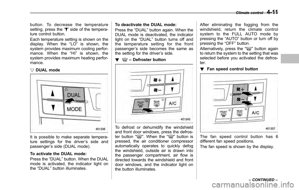
It is possible to make separate tempera-
ture settings for the driver ’s side and
passenger ’s side (DUAL mode).
To activate the DUAL mode:
Press the “DUAL ”button. When the DUAL
mode is activated, the indicator light on the “DUAL ”button illuminates. To deactivate the DUAL mode:
Press the
“DUAL ”button again. When the
DUAL mode is deactivated, the indicator
light on the “DUAL ”button turns off and
the temperature setting for the frontpassenger ’s side becomes the same as
the setting for the driver ’s side.
!
– Defroster button
To defrost or dehumidify the windshield
and front door windows, press the defros-
ter button “
”. When the “”button is
pressed, the air conditioner compressor
automatically operates to quickly defog
the windshield, outside air is drawn into
the passenger compartment, air flow is
directed towards the windshield and front
door windows, and the indicator light on
the button illuminates. After eliminating the fogging from the
windshield, return the climate control
systemtotheFULLAUTOmodeby
pressing the
“AUTO ”button or turn off by
pressing the “OFF ”button.
Alternatively, press the “
”button again
to return the system to the setting that was
selected before you activated the defros-
ter. ! Fan speed control button
The fan speed control button has 6
different fan speed positions.
The fan speed is shown by the display. Climate control
4-11
– CONTINUED –
Page 170 of 448
4-12Climate control
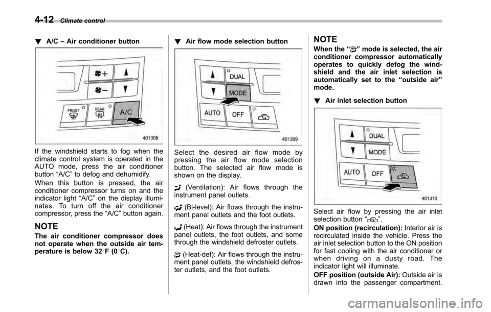
! A/C –Air conditioner button
If the windshield starts to fog when the
climate control system is operated in the
AUTO mode, press the air conditionerbutton “A/C ”to defog and dehumidify.
When this button is pressed, the air
conditioner compressor turns on and the
indicator light “A/C ”on the display illumi-
nates. To turn off the air conditioner
compressor, press the “A/C ”button again.
NOTE
The air conditioner compressor does
not operate when the outside air tem-
perature is below 32 8F(0 8C). !
Air flow mode selection buttonSelect the desired air flow mode by
pressing the air flow mode selection
button. The selected air flow mode is
shown on the display.
(Ventilation): Air flows through the
instrument panel outlets.
(Bi-level): Air flows through the instru-
ment panel outlets and the foot outlets.
(Heat): Air flows through the instrument
panel outlets, the foot outlets, and some
through the windshield defroster outlets.
(Heat-def): Air flows through the instru-
ment panel outlets, the windshield defros-
ter outlets, and the foot outlets. NOTE
When the
“
”mode is selected, the air
conditioner compressor automatically
operates to quickly defog the wind-
shield and the air inlet selection is
automatically set to the “outside air ”
mode. ! Air inlet selection button
Select air flow by pressing the air inlet
selection button “”.
ON position (recirculation): Interior air is
recirculated inside the vehicle. Press the
air inlet selection button to the ON position
for fast cooling with the air conditioner or
when driving on a dusty road. The
indicator light will illuminate.
OFF position (outside Air): Outside air is
drawn into the passenger compartment.
Page 172 of 448
4-14Climate control
Operating tips for heater and
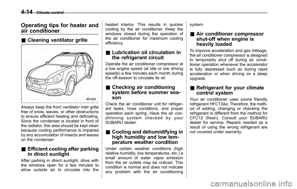
air conditioner &Cleaning ventilator grille
Always keep the front ventilator inlet grille
free of snow, leaves, or other obstructions
to ensure efficient heating and defrosting.
Since the condenser is located in front of
the radiator, this area should be kept clean
because cooling performance is impaired
by any accumulation of insects and leaves
on the condenser. &Efficient cooling after parking
in direct sunlight
After parking in direct sunlight, drive with
the windows open for a few minutes to
allow outside air to circulate into the heated interior. This results in quicker
cooling by the air conditioner. Keep the
windows closed during the operation of
the air conditioner for maximum cooling
efficiency.
& Lubrication oil circulation in
the refrigerant circuit
Operate the air conditioner compressor at
a low engine speed (at idle or low driving
speeds) a few minutes each month during
the off-season to circulate its oil. & Checking air conditioning
system before summer sea-son
Check the air conditioner unit for refriger-
ant leaks, hose conditions, and proper
operation each spring. Have the air con-
ditioning system checked by your
SUBARU dealer. & Cooling and dehumidifying in
high humidity and low tem-
perature weather condition
Under certain weather conditions (high
relative humidity, low temperatures, etc.) a
small amount of water vapor emission
from the air outlets may be noticed. This
condition is normal and does not indicate
any problem with the air conditioning system.
& Air conditioner compressor
shut-off when engine is
heavily loaded
To improve acceleration and gas mileage,
the air conditioner compressor is designed
to temporarily shut off during air condi-
tioner operation whenever the accelerator
is fully depressed such as during rapid
acceleration or when driving on a steepupgrade. & Refrigerant for your climate
control system
Your air conditioner uses ozone friendly
refrigerant HFC134a. Therefore, the meth-
od of adding, changing or checking the
refrigerant is different from the method for
CFC12 (freon). Consult your SUBARU
dealer for service. Repairs needed as a
result of using the wrong refrigerant are
not covered under warranty.
Page 243 of 448

Fuel...................................................................... 7-2
Fuel requirements ............................................... 7-2
Fuel filler lid and cap ........................................... 7-3
State emission testing (U.S. only) ...................... 7-6
Preparing to drive ............................................... 7-7
Starting the engine .............................................. 7-8
MT models .......................................................... 7-8
AT and CVT models ............................................. 7-9
Stopping the engine ........................................... 7-10
Remote engine start system (dealer option) ................................................. 7-10
Starting your vehicle .......................................... 7-11
Remote start safety features ............................... 7-11
Entering the vehicle while it is running via remote start ................................................................. 7-12
Remote start confirmation transmitter feature ............................................................. 7-12
Entering the vehicle following remote engine start shutdown ......................................................... 7-13
Pre-heating or pre-cooling the interior of the vehicle ............................................................. 7-13
Service mode ..................................................... 7-14
Remote transmitter program ............................... 7-14
System maintenance .......................................... 7-14
Manual transmission .......................................... 7-16
Selecting reverse gear ........................................ 7-16
Shifting speeds .................................................. 7-17
Driving tips ........................................................ 7-17
Automatic transmission/Continuously variable transmission ..................................... 7-18
Select lever ........................................................ 7-19 Shift lock function
............................................. 7-20
Selection of manual mode .................................. 7-21
Driving tips ........................................................ 7-23
Power steering ................................................... 7-23
Braking ............................................................... 7-23
Braking tips ....................................................... 7-23
Brake system .................................................... 7-24
Disc brake pad wear warning indicators ............. 7-24
ABS (Anti-lock Brake System) .......................... 7-25
ABS system self-check ...................................... 7-25
ABS warning light .............................................. 7-25
Electronic Brake Force Distribution (EBD) system ............................................................. 7-26
Steps to take if EBD system malfunctions ..... ..... 7-27
Vehicle Dynamics Control system .................... 7-28
Vehicle Dynamics Control system monitor..... ..... 7-29
Vehicle Dynamics Control OFF switch ................ 7-31
Tire pressure monitoring system (TPMS) (if equipped) .................................................... 7-32
Parking your vehicle ......................................... 7-33
Electronic parking brake .................................... 7-34
Parking tips ....................................................... 7-37
Cruise control .................................................... 7-38
To set cruise control .......................................... 7-38
To temporarily cancel the cruise control ............. 7-39
To turn off the cruise control .............................. 7-39
To change the cruising speed .. .......................... 7-40
Cruise control indicator light .............................. 7-41
Cruise control set indicator light ........................ 7-41
Starting and operating
7
Page 255 of 448

Transmitter flash sequence Feature description
Flashes when button is pressed Indicates that the system is transmitting an RF signal.
Two long flashes following re-
mote start activation (transmit-
ter button is pressed two times
within 3 seconds) Indicates that the transmitter did not receive the remote start
activation confirmation from the vehicle system. The transmitter
will automatically send one additional remote start activation
attempt. This usually occurs when the operational range is at its
limit or has been exceeded.
One flash following remote
start activation (transmitter
button is pressed two times
within 3 seconds) Indicates that the engine is running via remote start. If the
transmitter is moved outside of the operating range of the
system, this sequence will timeout after the normal 15-minute
vehicle run cycle.
2 flashes every 5 seconds Indicates that the engine is running via remote start. If the
transmitter is removed outside of the operating range of the
system, this sequence will timeout after the normal 15-minute
vehicle run cycle.
3 flashes Indicates that the engine has turned off due to a remote start
system 15-minute timeout, vehicle safety parameter or normal shutdown. &
Entering the vehicle follow-
ing remote engine start shut- down
An alarm trigger may occur if the vehicle is
opened by the remote keyless entry
transmitter within a few seconds immedi-
ately following remote engine start shut-down. & Pre-heating or pre-cooling
the interior of the vehicle
Models with automatic climate control system:
After the system starts the engine, the
automatic climate control system will
activate the “FULL AUTO ”mode and heat
or cool the interior to the predetermined
median (room) temperature. No pre-
setting of controls is necessary.
Models with manual climate control system:
Before exiting the vehicle, set the tem-
perature controls to the desired setting
and operation. After the system starts the
engine, the heater or air conditioning will
activate and heat or cool the interior to
your setting. Starting and operating
7-13
– CONTINUED –
Page 260 of 448
7-18Starting and operating
Automatic transmission/Con-
tinuously variable transmis-sion
The automatic transmission is electroni-
cally controlled and provides 5 forward
speeds and 1 reverse speed. The con-
tinuously variable transmission is electro-
nically controlled and provides an infinite
number of forward speeds and 1 reversespeed.
Both the automatic transmission and
continuously variable transmission have
a manual mode.
WARNING
Do not shift from the “P ” or “N ”
position into the “D ” or “R ” position
while depressing the accelerator
pedal. This may cause the vehicle
to jump forward or backward.
CAUTION
. Shift into the “P ” or “R ” position
only after the vehicle is comple-
tely stopped. Shifting while the
vehicle is moving may cause
damage to the transmission.
. Do not race the engine for more than 5 seconds in any position
except the
“N ” or “P ” position
when the brake is applied or
when chocks are used in the
wheels. This may cause the
transmission fluid to overheat.
. Avoid shifting from one of the
forward driving positions into the“ R ” position or vice versa until
the vehicle has completely
stopped. Such shifting may
cause damage to the transmis-sion.
. When parking the vehicle, first
securely apply the parking brake
and then place the select lever inthe “P ” position. Avoid parking
for a long time with the select
lever in any other position as
doing so could result in a dead
battery.
NOTE . For AT models, when the engine
coolant temperature is still low, the
transmission will upshift to higher
engine speeds than when the coolant
temperature is sufficiently high in order
to shorten the warm-up time and
improve driveability. The gearshift tim-
ing will automatically shift to the nor- mal timing after the engine has warmedup..
Immediately after transmission fluid
is replaced, you may feel that the
transmission operation is somewhat
unusual. This results from invalidation
of data which the on-board computer
has collected and stored in memory to
allow the transmission to shift at the
most appropriate times for the current
condition of your vehicle. Optimized
shifting will be restored as the vehicle
continues to be driven for a while.. When driving a vehicle that is
equipped with CVT under continuous
heavy load conditions such as towing a
camper or climbing a long, steep hill,
the engine speed or the vehicle speed
may automatically be reduced. This is
not a malfunction. This phenomenon
results from the engine control func-
tion maintaining the cooling perfor-
mance of the vehicle. The engine and
vehicle speed will return to a normal
speed when the engine is able to
maintain the optimum cooling perfor-
mance after the heavy load decreases.
Driving under a heavy load must be
performed with extreme care. Do not
try to pass a vehicle in front when
driving on an uphill slope while towing.. The continuously variable transmis-
sion is a chain type system that
Page 320 of 448
9-10In case of emergency
Jump starting
WARNING
. Battery fluid is SULFURIC ACID.
Do not let it come in contact with
the eyes, skin, clothing or thevehicle.
If battery fluid gets on you,
thoroughly flush the exposed
area with water immediately. Get
medical help if the fluid has
entered your eyes.
If battery fluid is accidentally
swallowed, immediately drink a
large amount of milk or water,
and obtain immediate medicalhelp.
Keep everyone including chil-
dren away from the battery.
. The gas generated by a battery
explodes if a flame or spark is
brought near it. Do not smoke or
light a match while jump starting.
. Never attempt jump starting if the
discharged battery is frozen. It
could cause the battery to burst
or explode.
. Whenever working on or around
a battery, always wear suitable eye protectors, and remove metal
objects such as rings, bands or
other metal jewelry.
. Be sure the jumper cables and
clamps on them do not have
loose or missing insulation.
. Do not jump start unless cables
in suitable condition are avail-able.
. A running engine can be danger-
ous. Keep your fingers, hands,
clothing, hair and tools away
from the cooling fan, belts and
any other moving engine parts.
Removing rings, watches and
ties is advisable.
. Jump starting is dangerous if it is
done incorrectly. If you are un-
sure about the proper procedure
for jump starting, consult a com-
petent mechanic.
When your vehicle does not start due to a
run down (discharged) battery, the vehicle
may be jump started by connecting your
battery to another battery (called the
booster battery) with jumper cables. &
How to jump start
1. Make sure the booster battery is 12
volts and the negative terminal isgrounded.
2. If the booster battery is in another
vehicle, do not let the two vehicles touch.
3. Turn off all unnecessary lights and accessories.
4. Connect the jumper cables exactly in
the sequence illustrated.