wheel torque SUBARU LEGACY 2017 6.G Owners Manual
[x] Cancel search | Manufacturer: SUBARU, Model Year: 2017, Model line: LEGACY, Model: SUBARU LEGACY 2017 6.GPages: 610
Page 395 of 610
Starting and operating/Manual transmission
&Shifting speeds
! Recommended shifting speeds
The best compromise between fuel econ-
omy and vehicle performance during
normal driving is ensured by shifting up
at the speeds listed in the following table.
Shift up mph (km/h)
1st to 2nd 15 (24)
2nd to 3rd 25 (40)
3rd to 4th 40 (64)
4th to 5th 45 (72)
5th to 6th 50 (80)
!
Maximum allowable speeds
WARNING
When shifting down a gear, ensure
that the vehicle is not travelling at a
speed exceeding the Maximum Al-
lowable Speed for the gear which is
about to be selected. Failure to
observe this precaution can lead to
engine over-revving and this in turn
can result in engine damage.
In addition, sudden application of
engine brakes when the vehicle is
travelling on a slippery surface can
lead to wheel locking; as a conse- quence, control of the vehicle may
be lost and the risk of an accident
increased.
The following table shows the maximum
speeds that are possible with each differ-
ent gear. The tachometer ’s needle will
enter the red area if these speeds are
exceeded.
With the exception of cases where sudden
acceleration is required, the vehicle
should not be driven with the tachometer ’s
needle inside the red area. Failure to
observe this precaution can lead to
excessive engine wear and poor fuel
economy.
mph (km/h)
Gear Legacy Outback
1st 30 (49) 30 (48)
2nd 57 (92) 56 (90)
3rd
Legal speed limit
(Posted limit speed)
4th
5th
6th
NOTE
Never exceed posted speed limits.
&
Driving tips
NOTE
If the accelerator and brake pedals are
depressed at the same time, driving
torque may be restrained. This is not a
malfunction.
Do not drive with your foot resting on the
clutch pedal and do not use the clutch to
hold your vehicle at a standstill on an
upgrade. Either of those actions may
cause clutch damage.
Do not drive with your hand resting on the
shift lever. This may cause wear on the
transmission components.
When it is necessary to reduce vehicle
speed due to slow traffic, turning corners,
or driving up steep hills, downshift to a
lower gear before the engine starts to
labor.
On steep downgrades, downshift the
transmission to 5th, 4th, 3rd or 2nd gear
as necessary; this helps to maintain a safe
speed and to extend brake pad life.
In this way, the engine provides a braking
effect. Remember, if you “ride”(over use)
the brakes while descending a hill, they
may overheat and not work properly.
The engine may, on rare occasions, knock
when the vehicle rapidly accelerates or
7-24
Page 402 of 610
&Driving tips
NOTE
If the accelerator and brake pedals are
depressed at the same time, driving
torque may be restrained. This is not a
malfunction.
. On a road surface where there is a risk
of wheelspin (for example, a snow- or
gravel-covered road), you can pull away
from a standstill safely and easily by first
selecting the 2nd gear of the manual
mode.
. Always apply the foot or parking brake
when the vehicle is stopped in the “D”or
“R ”position.
. Make sure to apply the parking brake
when parking your vehicle. Do not hold
the vehicle with only the transmission.
. Do not keep the vehicle in a stationary
position on an uphill grade by using the
“D ”position. Use the brake instead.
. The engine may, on rare occasions,
knock when the vehicle rapidly acceler-
ates or rapidly pulls away from a standstill.
This phenomenon does not indicate a
malfunction.
. A slight reduction in output torque may
occur in the models with a 3.6 L engine
before the engine warms up.
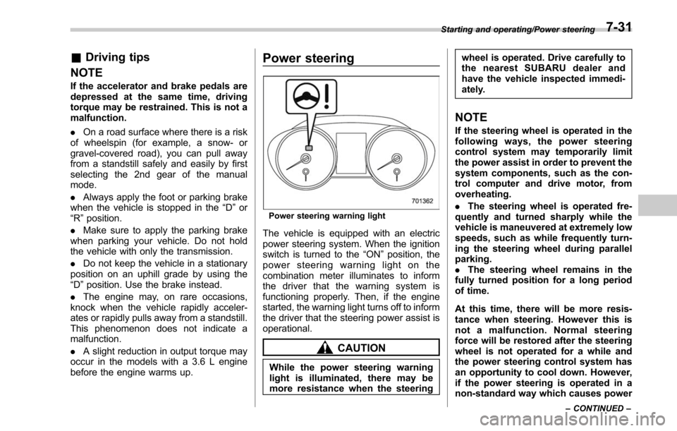
Power steering
Power steering warning light
The vehicle is equipped with an electric
power steering system. When the ignition
switch is turned to the “ON”position, the
power steering warning light on the
combination meter illuminates to inform
the driver that the warning system is
functioning properly. Then, if the engine
started, the warning light turns off to inform
the driver that the steering power assist is
operational.
CAUTION
While the power steering warning
light is illuminated, there may be
more resistance when the steering wheel is operated. Drive carefully to
the nearest SUBARU dealer and
have the vehicle inspected immedi-
ately.
NOTE
If the steering wheel is operated in the
following ways, the power steering
control system may temporarily limit
the power assist in order to prevent the
system components, such as the con-
trol computer and drive motor, from
overheating.
.
The steering wheel is operated fre-
quently and turned sharply while the
vehicle is maneuvered at extremely low
speeds, such as while frequently turn-
ing the steering wheel during parallel
parking.
. The steering wheel remains in the
fully turned position for a long period
of time.
At this time, there will be more resis-
tance when steering. However this is
not a malfunction. Normal steering
force will be restored after the steering
wheel is not operated for a while and
the power steering control system has
an opportunity to cool down. However,
if the power steering is operated in a
non-standard way which causes power
Starting and operating/Power steering
–CONTINUED –7-31
Page 410 of 610
door pillar.
– Use only the special tempor-
ary spare tire to replace a flat
tire. With a normal temporary
spare tire, the effectiveness of
the X-mode is reduced and
this should be taken into ac-
count when driving the vehi-
cle in such a condition.
. If the hill descent control function
has operated continuously for a
long time, the temperature of the
brake disc may increase and the
hill descent control function may
be temporarily disabled. In this
case, the hill descent control
indicator will disappear. When
the hill descent control indicator
disappears, the hill descent con-
trol function is disabled.
X-mode is the integrated control system of
the engine, AWD and Vehicle Dynamics
Control system, etc. for driving with bad
road conditions. Using X-mode, you can
drive more comfortably even in slippery
road conditions including uphill and down-
hill. X-mode has the following functions.
.
Hill descent control function:
Using the hill descent control function, you
can keep the vehicle at a consistent speed
driving downhill. If the vehicle speed is
likely to increase, the brake control system
will be activated to adjust the vehicle
speed.
. Driving ability control:
This mode increases the hill-climbing
ability and driving ability as well as
enabling smooth application of torque for
easier control of the steering wheel.
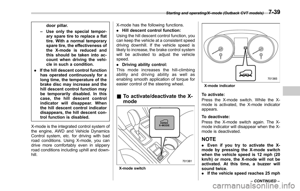
& To activate/deactivate the X-
mode
X-mode switch
X-mode indicator
To activate:
Press the X-mode switch. While the X-
mode is activated, the X-mode indicator
appears.
To deactivate:
Press the X-mode switch again. The X-
mode indicator will disappear when the X-
mode is deactivated.
NOTE
. Even if you try to activate the X-
mode by pressing the X-mode switch
when the vehicle speed is 12 mph (20
km/h) or more, the X-mode will not be
activated. At this time, a buzzer will
sound twice.
. If the vehicle speed reaches 25 mph
Starting and operating/X –mode (Outback CVT models)
–CONTINUED –7-39
Page 476 of 610
CAUTION
Never use any temporary spare tire
other than the original. Using other
sizes may result in severe mechan-
ical damage to the drive train of your
vehicle.
The temporary spare tire is stored under
the under-floor storage compartment.
The temporary spare tire is smaller and
lighter than a conventional tire and is
designed for emergency use only. Re-
move the temporary spare tire and re-
install the conventional tire as soon as
possible because the spare tire is de-
signed only for temporary use.
Check the inflation pressure of the tem-
porary spare tire periodically to keep the
tire ready for use. The correct pressure is
60 psi (420 kPa, 4.2 kgf/cm
2).
When using the temporary spare tire, note
the following precautions.
. Do not exceed 50 mph (80 km/h).
. Do not put a tire chain on the temporary
spare tire. Because of the smaller tire size,
a tire chain will not fit properly.
. Do not use two or more temporary
spare tires at the same time.
. Do not drive over obstacles. This tire has a smaller diameter, so road clearance
is reduced.
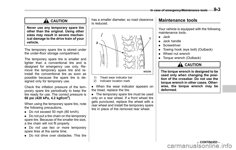
1) Tread wear indicator bar
2) Indicator location mark
.
When the wear indicator appears on
the tread, replace the tire.
. The temporary spare tire must be used
only on a rear wheel. If a front wheel tire
gets punctured, replace the wheel with a
rear wheel and install the temporary spare
tire in place of the removed rear wheel.
Maintenance tools
Your vehicle is equipped with the following
maintenance tools.
. Jack
. Jack handle
. Screwdriver
. Towing hook (eye bolt) (Outback)
. Wheel nut wrench
. Torque wrench (Outback)
CAUTION
The torque wrench is designed to be
used only when changing the posi-
tion of the crossbar. Do not use the
torque wrench in other cases. Other-
wise, the torque wrench may be
deformed.
In case of emergency/Maintenance tools
–CONTINUED –9-3
Page 478 of 610
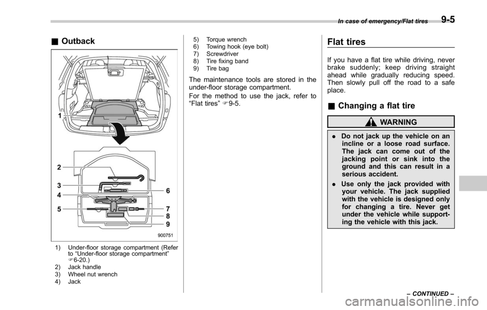
&Outback
1) Under-floor storage compartment (Refer
to“Under-floor storage compartment”
F 6-20.)
2) Jack handle
3) Wheel nut wrench
4) Jack 5) Torque wrench
6) Towing hook (eye bolt)
7) Screwdriver
8) Tire fixing band
9) Tire bag
The maintenance tools are stored in the
under-floor storage compartment.
For the method to use the jack, refer to
“
Flat tires ”F 9-5.
Flat tires
If you have a flat tire while driving, never
brake suddenly; keep driving straight
ahead while gradually reducing speed.
Then slowly pull off the road to a safe
place.
& Changing a flat tire
WARNING
. Do not jack up the vehicle on an
incline or a loose road surface.
The jack can come out of the
jacking point or sink into the
ground and this can result in a
serious accident.
. Use only the jack provided with
your vehicle. The jack supplied
with the vehicle is designed only
for changing a tire. Never get
under the vehicle while support-
ing the vehicle with this jack.
In case of emergency/Flat tires
–CONTINUED –9-5
Page 481 of 610
In case of emergency/Flat tires
13. Before putting the spare tire on, clean
the mounting surface of the wheel and hub
with a cloth.
14. Put on the spare tire. Replace the
wheel nuts. Tighten them by hand.
WARNING
Do not use oil or grease on the
wheel studs or nuts when the spare
tire is installed. This could cause the
nuts to become loose and lead to an
accident.
15. Turn the jack handle counterclockwise
to lower the vehicle.
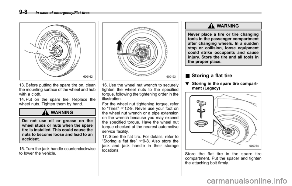
16. Use the wheel nut wrench to securely
tighten the wheel nuts to the specified
torque, following the tightening order in the
illustration.
For the wheel nut tightening torque, refer
to “Tires ”F 12-9. Never use your foot on
the wheel nut wrench or a pipe extension
on the wrench because you may exceed
the specified torque. Have the wheel nut
torque checked at the nearest automotive
service facility.
17. Store the flat tire. For details, refer to
“Storing a flat tire ”F 9-8. Also store the
jack and jack handle in their storage
locations.
WARNING
Never place a tire or tire changing
tools in the passenger compartment
after changing wheels. In a sudden
stop or collision, loose equipment
could strike occupants and cause
injury. Store the tire and all tools in
the proper place.
& Storing a flat tire
! Storing in the spare tire compart-
ment (Legacy)
Store the flat tire in the spare tire
compartment. Put the spacer and tighten
the attaching bolt firmly.
9-8
Page 535 of 610
Maintenance and service/Aluminum wheels
Aluminum wheels
Aluminum wheels can be scratched and
damaged easily. Handle them carefully to
maintain their appearance, performance,
and safety.
.When any of the wheels is removed
and replaced for tire rotation or to change
a flat, always check the tightness of the
wheel nuts after driving approximately 600
miles (1,000 km). If any nut is loose,
tighten it to the specified torque.
. Never apply oil to the threaded parts,
wheel nuts, or tapered surface of the
wheel.
. Never let the wheel rub against sharp
protrusions or curbs.
. When wheel nuts, balance weights, or
the center cap is replaced, be sure to
replace them with genuine SUBARU parts
designed for aluminum wheels.
Windshield washer fluid
CAUTION
Never use engine coolant as washer
fluid because it could cause paint
damage.
Windshield washer fluid warning indicator
When there is only a small amount of
washer fluid remaining, the windshield
washer fluid warning indicator will appear.
When this occurs, refill the washer fluid as
follows.
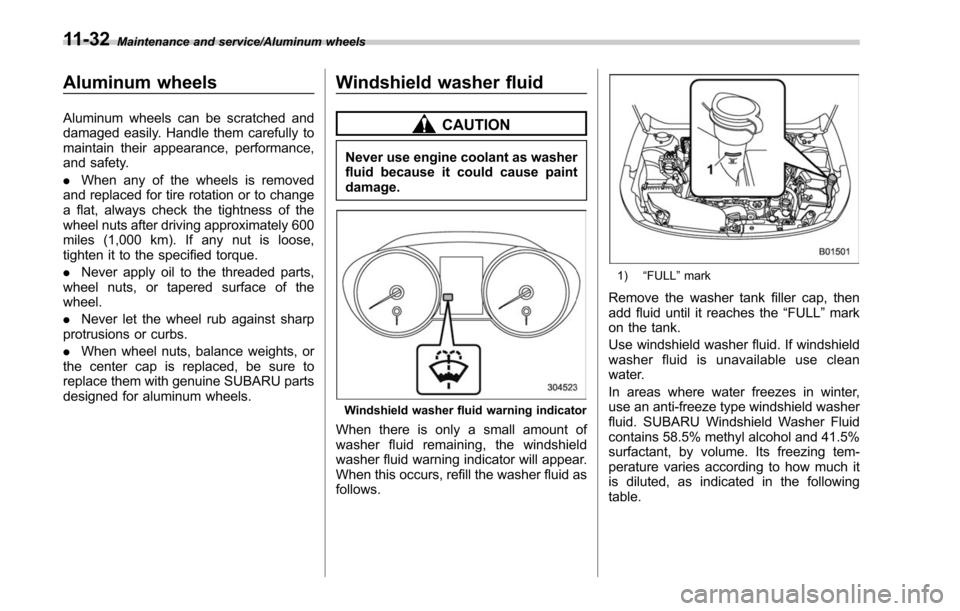
1) “FULL ”mark
Remove the washer tank filler cap, then
add fluid until it reaches the “FULL”mark
on the tank.
Use windshield washer fluid. If windshield
washer fluid is unavailable use clean
water.
In areas where water freezes in winter,
use an anti-freeze type windshield washer
fluid. SUBARU Windshield Washer Fluid
contains 58.5% methyl alcohol and 41.5%
surfactant, by volume. Its freezing tem-
perature varies according to how much it
is diluted, as indicated in the following
table.
11-32
Page 564 of 610
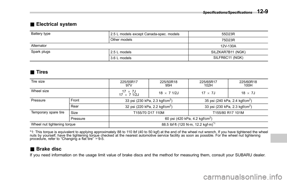
&Electrical system
Battery type
2.5 L models except Canada-spec. models 55D23R
Other models 75D23R
Alternator 12V-130A
Spark plugs 2.5 L models SILZKAR7B11 (NGK)
3.6 L models SILFR6C11 (NGK)
&
Tires
Tire size
225/55R17
97V 225/50R18
95H 225/65R17
102H 225/60R18
100H
Wheel size 1767J
17 67 1/2J 18
67 1/2J 17 67J 18 67J
Pressure Front 33 psi (230 kPa, 2.3 kgf/cm
2)35 psi (240 kPa, 2.4 kgf/cm2)
Rear 32 psi (220 kPa, 2.2 kgf/cm2)33 psi (230 kPa, 2.3 kgf/cm2)
Temporary spare tire Size T155/70 D17 110M T155/80 R17 101M
Pressure 60 psi (420 kPa, 4.2 kgf/cm
2)
Wheel nut tightening torque 88.5 lbf·ft (120 N·m, 12.2 kgf·m)*1
*1: This torque is equivalent to applying approximately 88 to 110 lbf (40 to 50 kgf) at the end of the wheel nut wrench. If you have tightened the wheel
nuts by yourself, have the tightening torque checked at the nearest automotive service facility as soon as possible. For the wheel nut tightening
procedure, refer to“Changing a flat tire ”F 9-5.
& Brake disc
If you need information on the usage limit value of brake discs and the method for measuring them, consult your SUBARU dealer.
Specifications/Specifications12-9
Page 583 of 610
Consumer information and Reporting safety defects/Tire information
.To maximize the life of each tire
and ensure that the tires wear
uniformly, it is best to rotate the
tires every 7,500 miles (12,000 km).
Rotating the tires involves switch-
ing the front and rear tires on the
right-hand side of the vehicle and
similarly switching the front and
rear tires on the left-hand side of
the vehicle. (Each tire must be kept
on its original side of the vehicle.)
Replace any damaged or unevenly
worn tire at the time of rotation.
After tire rotation, adjust the tire
pressures and make sure the wheel
nuts are correctly tightened. For
information about the tightening
torque and tightening sequence
for the wheel nuts, refer to “Flat
tires ”F 9-5.
& Vehicle load limit –how to
determine
The load capacity of your vehicle is
determined by weight, not by avail-
able cargo space. The load limit of
your vehicle is shown on the
vehicle placard attached to the driver
’s side B-pillar. Locate the
statement “The combined weight
of occupants and cargo should
never exceed XXX kg or XXX lbs ”
on your vehicle ’s placard.
Thevehicleplacardalsoshows
seating capacity of your vehicle.
The total load capacity includes the
total weight of driver and all pas-
sengers and their belongings, any
cargo, any optional equipment such
as a trailer hitch, roof rack or bike
carrier, etc., and the tongue load of
a trailer. Therefore cargo capacity
can be calculated by the following
method.
Cargo capacity = Load limit −(total
weight of occupants + total weight
of optional equipment + tongue
load of a trailer (if applicable))
For towing capacity information and
weight limits, refer to “Trailer towing
(Outback) ”F 8-22.
! Calculating total and load ca-
pacities varying seating con-
figurations
Calculate the available load capa-
city as shown in the following
examples:
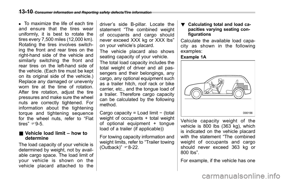
Example 1A
Vehicle capacity weight of the
vehicle is 800 lbs (363 kg), which
is indicated on the vehicle placard
with the statement “The combined
weight of occupants and cargo
should never exceed 363 kg or
800 lbs ”.
For example, if the vehicle has one
13-10
Page 601 of 610
14-12Index
Low fuel................................................................ 3-22
Low tire pressure ................................................... 3-17
Oil pressure .......................................................... 3-16
Power steering ...................................................... 3-23
Seatbelt ................................................................ 3-13
SRS airbag system ................................................ 3-15
Vehicle Dynamics Control ....................................... 3-24
Windshield washer fluid .......................................... 3-23
Warning volume
BSD/RCTA ............................................................ 3-45
EyeSight system .................................................... 3-44
Warranties ..................................................................... 1
Warranties and maintenance ....................................... 8-22
Washing ................................................................... 10-2
Waxing and polishing ................................................. 10-3
Wear indicators ......................................................... 11-29
Welcome lighting function ........................................... 3-48
Wheel Aluminum ............................................................. 11-32
Balance ............................................................... 11-29
Nut tightening torque .............................................. 12-9
Replacement ........................................................ 11-31
Windows ................................................................... 2-34
Windshield Washer fluid ......................................................... 11-32
Wiper and washer switches ..................................... 3-59
Wiper blades ........................................................ 11-34
Wiper deicer .......................................................... 3-61
Winter
Driving .................................................................... 8-8
Tires ............................................................ 8-11, 11-25 Wiper and washer
...................................................... 3-57
Wiper deicer .............................................................. 3-61
X
X-mode ..................................................................... 7-38
Indicator ................................................................ 3-32