SUBARU OUTBACK 2005 4.G Owners Manual
Manufacturer: SUBARU, Model Year: 2005, Model line: OUTBACK, Model: SUBARU OUTBACK 2005 4.GPages: 627, PDF Size: 6.42 MB
Page 171 of 627

2-46
Keys and doors
back.
Page 172 of 627

3-1
3
Instruments and controls
Ignition switch .............................................. 3-3 LOCK .................................................................. 3-4
ACC .................................................................... 3-4
ON ....................................................................... 3-4
START ................................................................ 3-5
Key reminder chime .......................................... 3-6
Ignition switch light .......................................... 3-6
Hazard warning flasher ................................ 3-7
Meters and gauges (Turbo models) ............ 3-7 Combination meter illumination ...................... 3-7
Canceling the function for meter/gauge needle movement and combination meter
sequential illumination upon turning on the
ignition switch ................................................ 3-8
Speedometer ..................................................... 3-9
Odometer ........................................................... 3-9
Double trip meter .............................................. 3-10
Tachometer ........................................................ 3-11
Fuel gauge ......................................................... 3-11
Temperature gauge ........................................... 3-13
Meters and gauges (Non-turbo models) ..... 3-14 Combination meter illumination ...................... 3-14
Canceling the function for meter/gauge needle movement upon turning on the
ignition switch ................................................ 3-15
Speedometer ..................................................... 3-15
Odometer ........................................................... 3-16
Double trip meter .............................................. 3-16
Tachometer ........................................................ 3-17
Fuel gauge ......................................................... 3-18
Temperature gauge ........................................... 3-19 Warning and indicator lights ....................... 3-20
Seatbelt warning light and chime .................... 3-21
SRS airbag system warning light .................... 3-24
Front passenger’s frontal airbag ON and OFF indicators ........................................................ 3-24
CHECK ENGINE warning light/Malfunction indicator lamp ................................................. 3-25
Charge warning light ........................................ 3-26
Oil pressure warning light ............................... 3-26
AT OIL TEMPerature warning light (AT vehicles) ................................................... 3-27
Low tire pressure warning light (if equipped) .................................................... 3-27
ABS warning light ............................................. 3-28
Brake system warning light ............................. 3-29
Low fuel warning light ...................................... 3-30
Door open warning light .................................. 3-31
All-wheel drive warning light (AT vehicles) .... 3-31
Vehicle Dynamics Control operation indicator light (if equipped) ........................................... 3-31
Vehicle Dynamics Control warning light (if equipped)/Vehicle Dynamics Control OFF
indicator light (if equipped) ........................... 3-32
Security indicator light ..................................... 3-33
SPORT mode indicator light (AT vehicles) ..... 3-34
Selector lever position indicator (AT vehicles) ................................................... 3-34
Gear position indicator (AT vehicles) ............. 3-34
Turn signal indicator lights .............................. 3-34
High beam indicator light ................................. 3-35
Cruise control indicator light ........................... 3-35
Cruise control set indicator light .................... 3-35
Page 173 of 627

3-2
Instruments and controls
Headlight indicator light .................................. 3-35
Front fog light indicator light .......................... 3-35
Clock ............................................................. 3-36
Information display (if equipped) ................ 3-37 Outside temperature indicator ........................ 3-37
Current fuel consumption ................................ 3-39
Average fuel consumption .............................. 3-40
Driving range on remaining fuel ..................... 3-41
Journey time ..................................................... 3-43
Light control switch ..................................... 3-44 Headlights ......................................................... 3-45
High/low beam change (dimmer) .................... 3-45
Headlight flasher .............................................. 3-46
Daytime running light system ......................... 3-46
Turn signal lever ........................................... 3-47
Illumination brightness control ................... 3-47
Bright switch (Night illumination dimness cancellation) .............................................. 3-48
Parking light switch ..................................... 3-49
Fog light switch (if equipped) ..................... 3-50
Wiper and washer ......................................... 3-51 Windshield wiper and washer switches ......... 3-52
Rear window wiper and washer switch (Station wagon) .............................................. 3-55
Windshield wiper deicer (if equipped) ........ 3-56
Rear window defogger button ..................... 3-57
Mirrors ........................................................... 3-59 Inside mirror ...................................................... 3-59
Auto-dimming mirror/compass (if equipped) ................................................... 3-59
Outside mirrors ................................................. 3-61 Tilt steering wheel ........................................ 3-63
Horn ............................................................... 3-64
Page 174 of 627
3-3
Instruments and controls
– CONTINUED –
Instruments and controlsIgnition switch
"Never turn the ignition switch to “LOCK”
while the vehicle is being driven or towed be-
cause that will lock the steering wheel, prevent-
ing steering control. And when the engine is
turned off, it takes a much greater effort than
usual to steer. " Before leaving the vehicle, always remove
the key from the ignition switch for safety and
never allow an unattended child to remains in
the vehicle. Failure to follow this procedure
could result in injury to a child or others. They
could operate the power windows, the sunroof
or other controls or even make the vehicle
move.
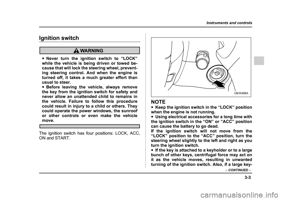
The ignition switch has four positions: LOCK, ACC,
ON and START.
NOTE " Keep the ignition switch in the “LOCK” position
when the engine is not running. " Using electrical accessories for a long time with
the ignition switch in the “ON” or “ACC” position
can cause the battery to go dead.
If the ignition switch will not move from the“LOCK” position to the “ACC” position, turn the
steering wheel slightly to the left and right as you turn the ignition switch." If the key is attached to a keyholder or to a large
bunch of other keys, centrifugal force may act on
it as the vehicle moves, resulting in unwanted
turning of the ignition switch. Also, if a large key-
UB3546BA
Page 175 of 627
3-4
Instruments and controls
holder is attached to the key, your knees or hands
may accidentally touch it in a way that turns the ig-
nition switch. !
LOCK
The key can only be inserted or removed in this posi-
tion. The ignition switch will lock the steering wheel when you remove the key.
If turning the key is difficult, turn the steering wheel
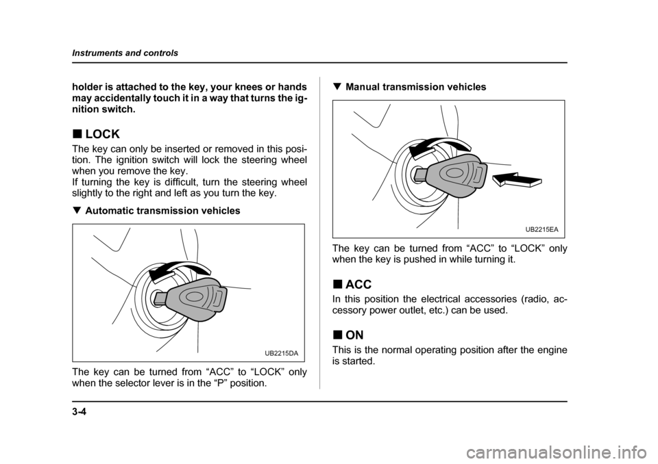
slightly to the right and left as you turn the key. ! Automatic transmission vehicles
The key can be turned from “ACC” to “LOCK” only
when the selector lever is in the “P” position. !
Manual transmission vehicles
The key can be turned from “ACC” to “LOCK” only
when the key is pushed in while turning it. ! ACC
In this position the electrical accessories (radio, ac-
cessory power outlet, etc.) can be used. ! ON
This is the normal operating position after the engine
is started.
UB2215DA
UB2215EA
Page 176 of 627
3-5
Instruments and controls
– CONTINUED –
!START
Do not turn the ignition switch to the “START”
position while the engine is running.
The engine is started in this position. The starter
cranks the engine to start it. When the key is released
(after the engine has started), the key automatically
returns to the “ON” position. ! For vehicle with immobilizer
If your registered key fails to start the engine, pull out
the key once (the security indicator light will blink), and
then insert the key in the ignition switch and turn it to
the “START” position to start the engine again.
NOTE
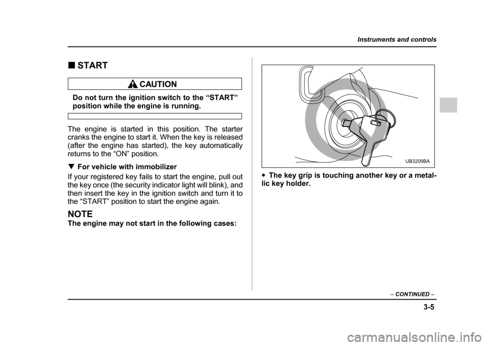
The engine may not start in the following cases: "
The key grip is touching another key or a metal-
lic key holder.
UB3209BA
Page 177 of 627
3-6
Instruments and controls
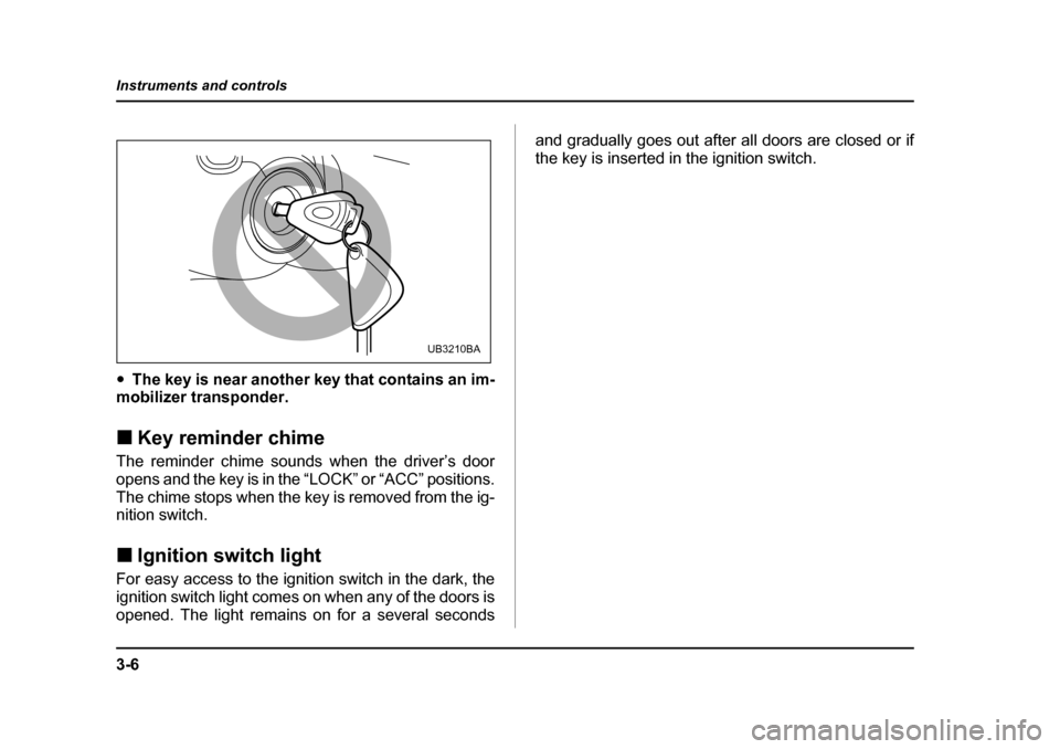
"
The key is near another key that contains an im-
mobilizer transponder. ! Key reminder chime
The reminder chime sounds when the driver’s door
opens and the key is in the “LOCK” or “ACC” positions.
The chime stops when the key is removed from the ig-
nition switch. ! Ignition switch light
For easy access to the ignition switch in the dark, the
ignition switch light comes on when any of the doors is
opened. The light remains on for a several seconds and gradually goes out after all doors are closed or if
the key is inserted in the ignition switch.
UB3210BA
Page 178 of 627
3-7
Instruments and controls
– CONTINUED –
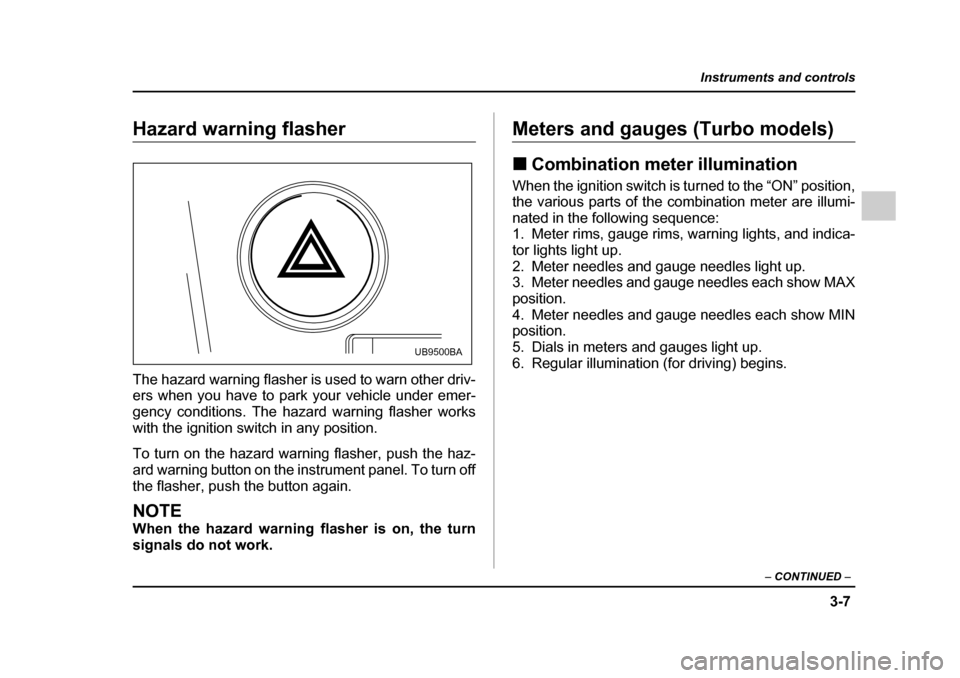
Hazard warning flasher
The hazard warning flasher is used to warn other driv-
ers when you have to park your vehicle under emer-
gency conditions. The hazard warning flasher works
with the ignition switch in any position.
To turn on the hazard warning flasher, push the haz-
ard warning button on the instrument panel. To turn off
the flasher, push the button again.
NOTE
When the hazard warning flasher is on, the turn
signals do not work.
Meters and gauges (Turbo models) !Combination meter illumination
When the ignition switch is turned to the “ON” position,
the various parts of the combination meter are illumi-
nated in the following sequence:
1. Meter rims, gauge rims, warning lights, and indica-
tor lights light up.
2. Meter needles and gauge needles light up.
3. Meter needles and gauge needles each show MAX
position.
4. Meter needles and gauge needles each show MIN
position.
5. Dials in meters and gauges light up.
6. Regular illumination (for driving) begins.
UB9500BA
Page 179 of 627
3-8
Instruments and controls
!
Canceling the function for meter/
gauge needle movement and combina-
tion meter sequential illumination
upon turning on the ignition switch
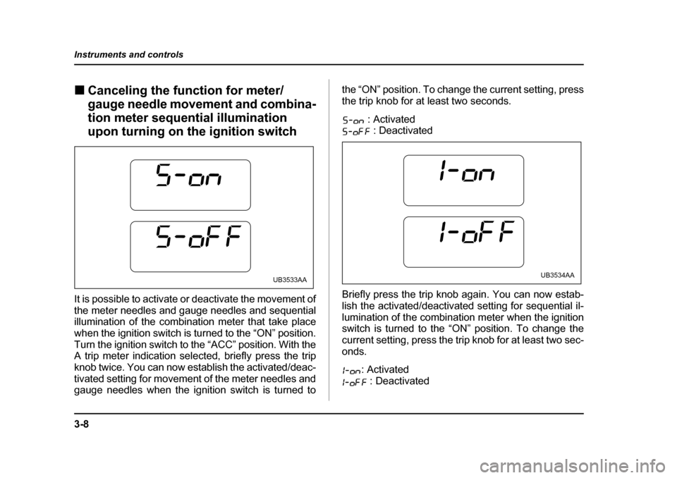
It is possible to activate or deactivate the movement of
the meter needles and gauge needles and sequential
illumination of the combination meter that take place
when the ignition switch is turned to the “ON” position.
Turn the ignition switch to the “ACC” position. With the
A trip meter indication selected, briefly press the trip
knob twice. You can now establish the activated/deac-
tivated setting for movement of the meter needles and
gauge needles when the ignition switch is turned to the “ON” position. To change the current setting, press
the trip knob for at least two seconds.
: Activated : Deactivated
Briefly press the trip knob again. You can now estab-
lish the activated/deactivated setting for sequential il-
lumination of the combination meter when the ignition
switch is turned to the “ON” position. To change the
current setting, press the trip knob for at least two sec-
onds. : Activated : Deactivated
UB3533AAUB3534AA
Page 180 of 627
3-9
Instruments and controls
– CONTINUED –
Briefly press the knob to return to the A trip meter indi-
cation.
If you turn the ignition switch to the “LOCK” position,
turn the ignition switch to the “ON” position, or open
and close the driver’s door during the setting proce-
dure, the new setting will be canceled.
Also, if you do not press the trip knob for a period of 10
seconds, the new setting will be canceled.
NOTE
It is not possible to cancel sequential illumination
of the combination meter while sequential illumi-
nation is actually taking place. Cancel sequential
illumination when regular illumination (for driving)
has begun. !Speedometer
The speedometer shows the vehicle speed. !
Odometer
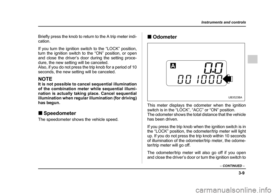
This meter displays the odometer when the ignition
switch is in the “LOCK”, “ACC” or “ON” position.
The odometer shows the total distance that the vehicle
has been driven.
If you press the trip knob when the ignition switch is in
the “LOCK” position, the odometer/trip meter will light
up. If you do not press the trip knob within 10 seconds
of illumination of the odometer/trip meter, the odome-
ter/trip meter will go off.
The odometer/trip meter will also go off if you open
and close the driver’s door or turn the ignition switch to
UB3523BA