sensor SUBARU OUTBACK 2005 4.G User Guide
[x] Cancel search | Manufacturer: SUBARU, Model Year: 2005, Model line: OUTBACK, Model: SUBARU OUTBACK 2005 4.GPages: 627, PDF Size: 6.42 MB
Page 121 of 627
1-90
Seat, seatbelt and SRS airbags
position.
The following components are monitored by the indi- cator: "
Front sub sensor (Right hand side)
" Front sub sensor (Left hand side)
" Airbag control module (including impact sensors)
" Frontal airbag module (Driver’s side)
" Frontal airbag module (Front passenger’s side)
" Side airbag sensor (Center pillar right hand side)
" Side airbag sensor (Center pillar left hand side)
" Side airbag module (Driver’s side)
" Side airbag module (Front passenger’s side)
" Side airbag sensor (Rear wheel house right hand
side) " Side airbag sensor (Rear wheel house left hand
side)" Curtain airbag module (Right side)
" Curtain airbag module (Left side)
" Seatbelt pretensioner (Driver’s side)
" Seatbelt pretensioner (Front passenger’s side)
" Seatbelt buckle switch (Driver’s side)
" Seatbelt buckle switch (Front passenger’s side)
" Driver’s seat position sensor
" Front passenger’s occupant detection system
weight sensor" Front passenger’s occupant detection control mod-
ule "
Front passenger’s frontal airbag ON and OFF indi-
cator" All related wiring
If the warning light exhibits any of the following
conditions, there may be a malfunction in the
seatbelt pretensioners and/or SRS airbag sys-
tem. Immediately take your vehicle to your
nearest SUBARU dealer to have the system
checked. Unless checked and properly re-
paired, the seatbelt pretensioners and/or SRS
airbags will operate improperly (e.g. SRS air-
bags may inflate in a very minor collision or not
inflate in a severe collision), which may in-
crease the risk of injury. "Flashing or flickering of the indicator light
" No illumination of the warning light when the
ignition switch is first turned to the “ON” posi- tion " Continuous illumination of the warning light
"Illumination of the warning light while driving
Page 122 of 627
1-91
Seat, seatbelt and SRS airbags
– CONTINUED –
!SRS airbag system servicing
"When discarding an airbag module or scrap-
ping the entire vehicle damaged by a collision,
consult your SUBARU dealer. " The SRS airbag has no user-serviceable
parts. Do not use electrical test equipment on
any circuit related to the SRS airbag system.
For required servicing of the SRS airbag, see
your nearest SUBARU dealer. Tampering with
or disconnecting the system’s wiring could re-
sult in accidental inflation of the SRS airbag or
could make the system inoperative, which may
result in serious injury. The wiring harnesses of
the SRS airbag system are covered with yellow
insulation and system connectors are yellow
for easy identification.
If you need service or repair in areas listed be-
low, have an authorized SUBARU dealer per-
form the work. The SRS airbag control module,
impact sensors and airbag modules are stored
in these areas. "
Under the center console
" Inside each front fender
" Steering wheel and column and nearby areas
" Top of the dashboard on front passenger’s
side and nearby areas" Each front seat and nearby area
" Inside each center pillar
" In each roof side (from the front pillar to a
point over the rear seat) " Between the rear seat cushion and rear wheel
house on each side
In the event that the SRS airbag is deployed, re-
placement of the system should be performed
only by an authorized SUBARU dealer. When the
components of the SRS airbag system are re-
placed, use only genuine SUBARU parts.
NOTE
In the following cases, contact your SUBARU deal-
er as soon as possible. " The front part of the vehicle was involved in an
accident in which the only the driver’s SRS frontal
airbag or both driver’s and front passenger’s SRS
frontal airbags did not deploy." The pad of the steering wheel, the cover over the
front passenger’s SRS frontal airbag, or either
Page 126 of 627

2-1
2
Keys and doors
Keys ............................................................... 2-2 Key number ....................................................... 2-3
Immobilizer (if equipped) ............................. 2-4 Security ID plate ................................................ 2-5
Security indicator light ..................................... 2-5
Key replacement ............................................... 2-6
Door locks ..................................................... 2-6 Locking and unlocking from the outside ........ 2-6
Locking and unlocking from the inside .......... 2-8
Battery drainage prevention function ............. 2-9
Power door locking switches ...................... 2-10 Key lock-in prevention function ...................... 2-11
Remote keyless entry system (if equipped) .............................................. 2-12Locking the doors ............................................. 2-13
Unlocking the doors ......................................... 2-14
Unlocking the trunk lid/rear gate ..................... 2-14
Illuminated entry ............................................... 2-15
Vehicle finder function ..................................... 2-15
Sounding a panic alarm ................................... 2-15
Selecting audible signal operation .................. 2-15
Replacing the battery ....................................... 2-16
Replacing lost transmitters .............................. 2-17
Alarm system ................................................ 2-23 System alarm operation ................................... 2-23
Activating and deactivating the alarm system ............................................................. 2-23
If you have accidentally triggered the alarm
system ............................................................. 2-24
Arming the system ............................................ 2-24
Disarming the system ....................................... 2-26 Valet mode ......................................................... 2-27
Passive arming ................................................. 2-27
Tripped sensor identification .......................... 2-29
Shock sensors (dealer option) ........................ 2-29
Child safety locks ......................................... 2-30
Windows ........................................................ 2-31 Power windows ................................................. 2-31
Trunk lid (Sedan) ........................................... 2-35 To open and close the trunk lid from outside ............................................................ 2-35
To open the trunk lid from inside .................... 2-36
To lock and unlock the trunk lid release lever ................................................................. 2-36
Internal trunk lid release handle ...................... 2-37
Rear gate (Station wagon) ............................ 2-39
Moonroof (if equipped) ................................. 2-41 Tilting/sliding moonroof (Sedan) .................... 2-42
Moonroof (Station wagon) ............................... 2-44
Page 148 of 627

2-23
Keys and doors
– CONTINUED –
Alarm system
The alarm system helps to protect your vehicle and
valuables from theft. The horn sounds and the turn
signal lights flash if someone attempts to break into your vehicle.
The system can be armed and disarmed with the re-
mote transmitter.
The system does not operate when the key is inserted
into the ignition switch.
Your vehicle’s alarm system has been set for activa-
tion at the time of shipment from the factory. You can
set the system for deactivation yourself or have it done
by your SUBARU dealer. !System alarm operation
The alarm system will give the following alarms when
triggered: " The vehicle’s horn will sound and the turn signal
lights will flash for 30 seconds. " If any door (or the rear gate/trunk lid) remains open
after the 30-second period, the horn will continue to
sound for a maximum of 3 minutes. If the door (or the
rear gate/trunk lid) is closed while the horn is sound-
ing, the horn will stop sounding with a delay of up to 30 seconds.
The alarm is triggered by: "
Opening a door, the rear gate or trunk lid
" Physical impact to the vehicle, such as forced entry
(only vehicles with shock sensors (dealer option)) ! Activating and deactivating the alarm
system
To change the setting of your vehicle’s alarm system
for activation or deactivation, do the following.
1. Disarm the alarm system (see “Disarming the sys-
tem” in this section).
2. Sit in the driver’s seat and shut all doors (and the
rear gate if your vehicle is a Station wagon).
3. Cycle the ignition switch from “LOCK” to “ON” three
times within 10 seconds, finally placing it in the “ON”
position.
4. Within 10 seconds after step 3, open the driver’s
door and then close it. The current setting will be dis-
played on the odometer/trip meter screen.
5. Within 10 seconds after step 4, operate the driver’s
door locking switch as follows:
To deactivate:
Move the door locking switch to the unlock position
(toward the rear) three times. The odometer/trip meter
screen will display “AL OF”.
Page 154 of 627
2-29
Keys and doors
– CONTINUED –
!Tripped sensor identification
The security indicator light flashes when the alarm
system has been triggered. Also, the number of flash-
es indicates the location of unauthorized intrusion or
the severity of impact on the vehicle. " When the ignition switch is turned to the “ON” posi-
tion, the indicator light will light for 1 second and then
flash as follows: When a door or rear gate (Station wagon) was
opened: 5 times
When the trunk (Sedan) was opened: 4 times
When a strong impact or multiple impacts were
sensed: twice (only vehicles with shock sensors
(dealer option))
When a light impact was sensed: once (only vehi-
cles with shock sensors (dealer option))
! Shock sensors (dealer option)
The shock sensors trigger the alarm system when
they sense impacts applied to the vehicle and when
any of their electric wires is cut. The alarm system
causes the horn to sound and the turn signal lights to
flash for a short time when the sensed impact is weak,
but it warns of a strong impact or multiple impacts by
sounding the horn and flashing the turn signal lights,
both lasting approximately 30 seconds. If you desire, your SUBARU dealer can connect them
and set them for activation or deactivation.
NOTE "
The shock sensors are not always able to sense
impacts caused by breaking in, and cannot sense
an impact that does not cause vibration (such as
breaking the glass using a rescue hammer). " The shock sensors may sense vibration like
those shown below and trigger the alarm system.
Select the settings of the alarm system and shock
sensors appropriately depending on where you
usually park your vehicle.
Example: Vibration from construction site
Vibration in multistory car park
Vibration from trains
" You can have the sensitivity of the shock sen-
sors adjusted to your preference by your SUBARU
dealer.
Page 199 of 627
3-28
Instruments and controls
ing, you should have your Tire Pressure Moni-
toring System checked at a SUBARU dealer as
soon as possible.
If this light comes on while driving, never brake
suddenly and keep driving straight ahead while
gradually reducing speed. Then slowly pull off
the road to a safe place. Otherwise an accident
involving serious vehicle damage and serious
personal injury could occur.
If this light still comes on while driving after ad-
justing the tire pressure, a tire may have signif-
icant damage and a fast leak that causes the
tire to lose air rapidly. If you have a flat tire, re-
place it with a spare tire as soon as possible.
When a spare tire is mounted or a wheel rim is
replaced without the original pressure sensor/
transmitter being transferred, the Low tire pres-
sure warning light will flash. This indicates the
TPMS is unable to monitor all four road wheels.
Contact your SUBARU dealer as soon as possi-
ble for tire and sensor replacement and/or sys-
tem resetting. If the light flashes, promptly con-
tact a SUBARU dealer to have the system in-
spected.
The tire pressure monitoring system is NOT a
substitute for manually checking tire pressure.
The tire pressure should be checked periodical-
ly (at least monthly) using a tire gauge. After
any change to tire pressure(s), the tire pressure
monitoring system will not re-check tire infla-
tion pressures until the vehicle is first driven
more than 20 mph (32 km/h). Be sure to install
the specified size for the front and rear tires.
! ABS warning light
The ABS warning light comes on when the ignition
switch is turned to the “ON” position and goes out after
about two seconds.
This is an indication that the ABS system is working
properly.
If the warning light behaves as follows, the ABS
system may not work properly.
When the warning light is on, the ABS function
shuts down; however, the conventional brake
system continues to operate normally.
(U.S.) (Canada)
Page 230 of 627
3-59
Instruments and controls
– CONTINUED –
Mirrors
Always check that the inside and outside mirrors are
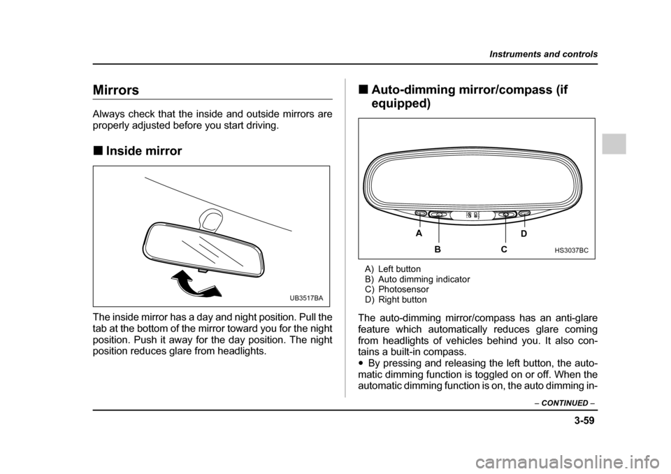
properly adjusted before you start driving. !Inside mirror
The inside mirror has a day and night position. Pull the
tab at the bottom of the mirror toward you for the night
position. Push it away for the day position. The night
position reduces glare from headlights. !
Auto-dimming mirror/compass (if
equipped)
A) Left button
B) Auto dimming indicator
C) Photosensor
D) Right button
The auto-dimming mirror/compass has an anti-glare
feature which automatically reduces glare coming
from headlights of vehicles behind you. It also con-
tains a built-in compass. " By pressing and releasing the left button, the auto-
matic dimming function is toggled on or off. When the
automatic dimming function is on, the auto dimming in-
UB3517BA
A
BC D
HS3037BC
Page 231 of 627
3-60
Instruments and controls
dicator light (green) located to the right of the button
will illuminate."
By pressing and releasing the right button, the com-
pass display is toggled on or off. When the compass is
on, an illuminated compass reading will appear in the
lower part of the mirror.
Even with the mirror in anti-glare mode, the mirror sur-
face turns bright if the transmission is shifted into re-
verse. This is to ensure good rearward visibility during reversing. ! Photosensors
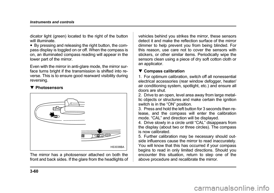
The mirror has a photosensor attached on both the
front and back sides. If the glare from the headlights of vehicles behind you strikes the mirror, these sensors
detect it and make the reflection surface of the mirror
dimmer to help prevent you from being blinded. For
this reason, use care not to cover the sensors with
stickers, or other similar items. Periodically wipe the
sensors clean using a piece of dry soft cotton cloth or
an applicator. !
Compass calibration
1. For optimum calibration, switch off all nonessential
electrical accessories (rear window defogger, heater/
air conditioning system, spotlight, etc.) and ensure all
doors are shut.
2. Drive to an open, level area away from large metal-
lic objects or structures and make certain the ignition
switch is in the “ON” position.
3. Press and hold the left button for 3 seconds then re-
lease, and the compass will enter the calibration
mode. “CAL” and direction will be displayed.
4. Drive slowly in a circle until “CAL” disappears from
the display (about two or three circles). The compass
is now calibrated.
5. Further calibration may be necessary should out-
side influences cause the mirror to read inaccurately.
You will know that this has occurred if your compass
begins to read in only limited directions. Should you
encounter this situation, return to step one of the
above procedure and recalibrate the mirror.
HS3038BA
Page 236 of 627

4-1
4
Climate control
Ventilator ....................................................... 4-2 Air flow selection .............................................. 4-2
Center and side ventilators .............................. 4-3
Manual climate control system (if equipped) ............................................... 4-4Control panel ..................................................... 4-4
Heater operation ............................................... 4-7
Air conditioner operation ................................. 4-9
Automatic climate control system (if equipped) ............................................... 4-10Temperature sensors ....................................... 4-16
Operating tips for heater and air conditioner ........................................... 4-17Cleaning ventilator grille .................................. 4-17
Efficient cooling after parking in direct sunlight ........................................................... 4-18
Lubrication oil circulation in the refrigerant
circuit .............................................................. 4-18
Checking air conditioning system before summer season .................................. 4-18
Cooling and dehumidifying in high humidity and low temperature weather condition ...... 4-18
Air conditioner compressor shut-off
when engine is heavily loaded ...................... 4-18
Refrigerant for your climate control system .. 4-18
Air filtration system (if equipped) ................ 4-19
Page 251 of 627
4-16
Climate control
ed, a “ ” indicator light appears on the display.
(Outside air): Outside air is drawn into the pas-
senger compartment. When the climate control sys-
tem is operated in the “AUTO” mode, this position is
selected automatically. (There is one exception: When
the temperature control dial is turned fully counter-
clockwise, the recirculation mode is automatically se-
lected.) When the outside air mode is selected, a
“ ” indicator light appears on the display.
Continued operation in the “ ” position
may fog up the windows. Switch to the
“ ” position as soon as the outside dusty
condition clears.
NOTE
When driving on a dusty road or behind a vehicle
that emits unpleasant exhaust gases, set the air
inlet selection button to the “ ” position.
From time to time, return the air inlet selection but-
ton to the “ ” position to draw outside air
into the passenger compartment. !
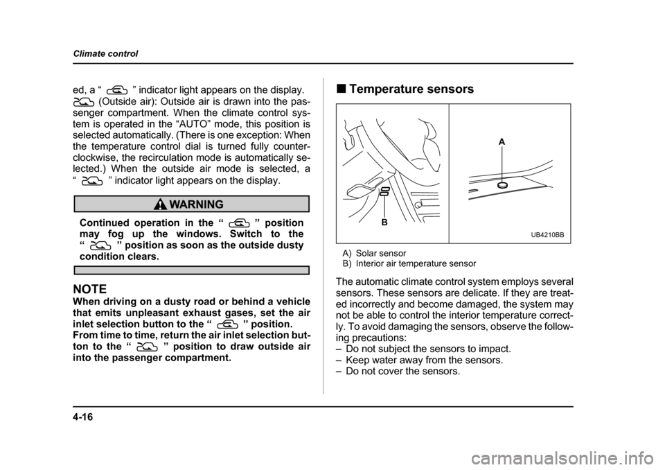
Temperature sensors
A) Solar sensor
B) Interior air temperature sensor
The automatic climate control system employs several
sensors. These sensors are delicate. If they are treat-
ed incorrectly and become damaged, the system may
not be able to control the interior temperature correct-
ly. To avoid damaging the sensors, observe the follow-
ing precautions:
– Do not subject the sensors to impact.
– Keep water away from the sensors.
– Do not cover the sensors.
A
B
UB4210BB