SUBARU OUTBACK 2005 4.G Owners Manual
Manufacturer: SUBARU, Model Year: 2005, Model line: OUTBACK, Model: SUBARU OUTBACK 2005 4.GPages: 627, PDF Size: 6.42 MB
Page 231 of 627
3-60
Instruments and controls
dicator light (green) located to the right of the button
will illuminate."
By pressing and releasing the right button, the com-
pass display is toggled on or off. When the compass is
on, an illuminated compass reading will appear in the
lower part of the mirror.
Even with the mirror in anti-glare mode, the mirror sur-
face turns bright if the transmission is shifted into re-
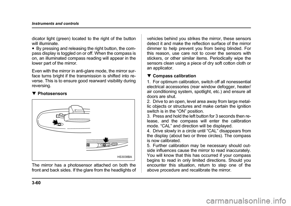
verse. This is to ensure good rearward visibility during reversing. ! Photosensors
The mirror has a photosensor attached on both the
front and back sides. If the glare from the headlights of vehicles behind you strikes the mirror, these sensors
detect it and make the reflection surface of the mirror
dimmer to help prevent you from being blinded. For
this reason, use care not to cover the sensors with
stickers, or other similar items. Periodically wipe the
sensors clean using a piece of dry soft cotton cloth or
an applicator. !
Compass calibration
1. For optimum calibration, switch off all nonessential
electrical accessories (rear window defogger, heater/
air conditioning system, spotlight, etc.) and ensure all
doors are shut.
2. Drive to an open, level area away from large metal-
lic objects or structures and make certain the ignition
switch is in the “ON” position.
3. Press and hold the left button for 3 seconds then re-
lease, and the compass will enter the calibration
mode. “CAL” and direction will be displayed.
4. Drive slowly in a circle until “CAL” disappears from
the display (about two or three circles). The compass
is now calibrated.
5. Further calibration may be necessary should out-
side influences cause the mirror to read inaccurately.
You will know that this has occurred if your compass
begins to read in only limited directions. Should you
encounter this situation, return to step one of the
above procedure and recalibrate the mirror.
HS3038BA
Page 232 of 627
3-61
Instruments and controls
– CONTINUED –
!Compass zone adjustment
1. The zone setting is factory preset to Zone 8. Refer
to the “Compass calibration zone” map attached to the
end of this manual to verify that the compass zone set-
ting is correct for your geographical location.
2. Press and hold the right button for 3 seconds then
release, and the word “ZONE” will briefly appear and
then the zone number will be displayed.
3. Press the right hand button repeatedly to cycle the
display through all possible zone settings. Stop cycling
when the correct zone setting for your location is dis-
played.
4. Releasing the button for 3 seconds will exit the
zone setting mode. ! Outside mirrors
! Convex mirror (Passenger side)
Objects look smaller in a convex mirror and far-
ther away than when viewed in a flat mirror. Do
not use the convex mirror to judge the distance
of vehicles behind you when changing lanes.
Use the inside mirror (or glance backwards) to
determine the actual size and distance of ob-
jects that you view in convex mirror.
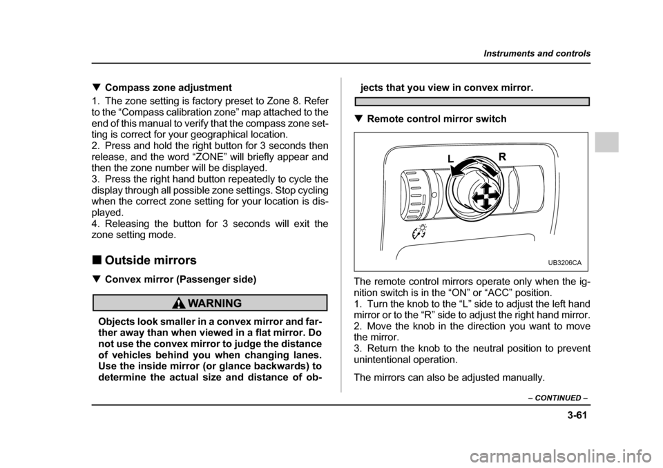
! Remote control mirror switch
The remote control mirrors operate only when the ig-
nition switch is in the “ON” or “ACC” position.
1. Turn the knob to the “L” side to adjust the left hand
mirror or to the “R” side to adjust the right hand mirror.
2. Move the knob in the direction you want to move
the mirror.
3. Return the knob to the neutral position to prevent
unintentional operation.
The mirrors can also be adjusted manually.
UB3206CA
Page 233 of 627
3-62
Instruments and controls
!
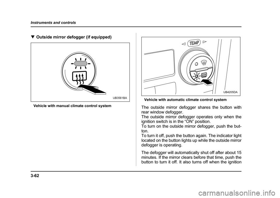
Outside mirror defogger (if equipped)
Vehicle with manual climate control system Vehicle with automatic climate control system
The outside mirror defogger shares the button with
rear window defogger.
The outside mirror defogger operates only when the
ignition switch is in the “ON” position.
To turn on the outside mirror defogger, push the but- ton.
To turn it off, push the button again. The indicator light
located on the button lights up while the outside mirror
defogger is operating.
The defogger will automatically shut off after about 15
minutes. If the mirror clears before that time, push the
button to turn it off. It also turns off when the ignition
UB3561BA
UB4205DA
Page 234 of 627
3-63
Instruments and controls
– CONTINUED –
switch is turned to the “ACC” or “LOCK” position. If de-
frosting or defogging is desired when you restart your
vehicle, you have to push the button to turn it on again.
NOTE "While the outside mirror defogger is operating,
the rear window defogger also operates. " When the rear window defogger has been set for
continuous operation, the outside mirror defogger
also operates continuously. Refer to the “Rear
window defogger button” section in this chapter.
To prevent the battery from being discharged,
do not operate the defogger continuously for
any longer than necessary.
Tilt steering wheel
Do not adjust the steering wheel tilt position
while driving. This may cause loss of vehicle
control and result in personal injury.
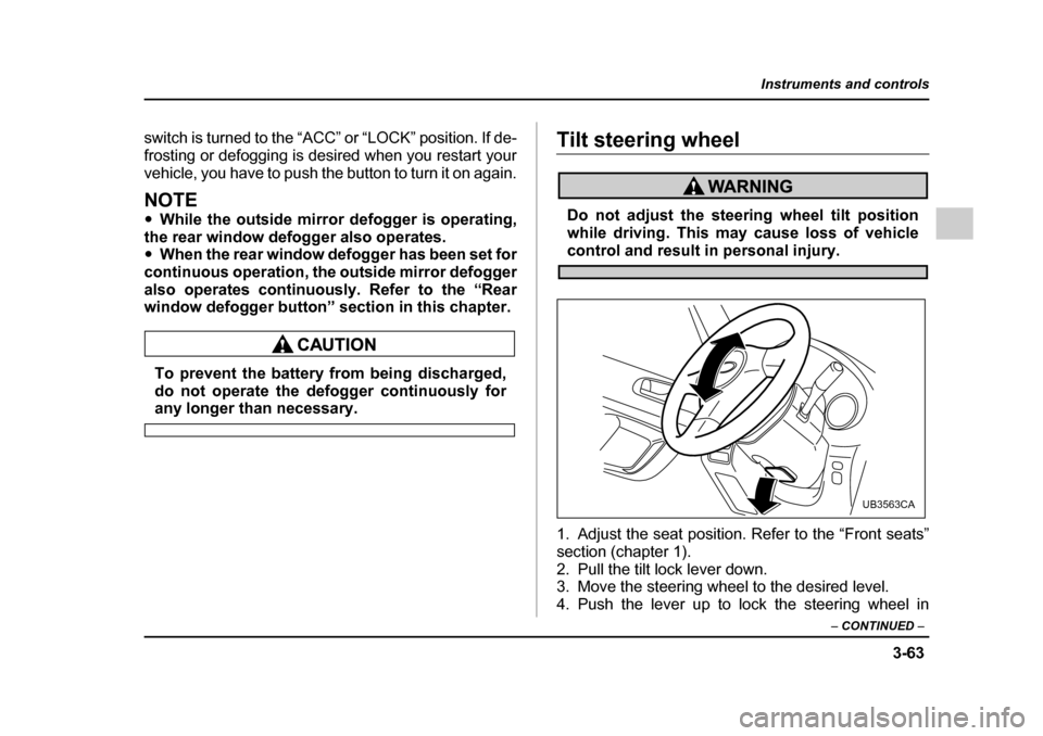
1. Adjust the seat position. Refer to the “Front seats”
section (chapter 1).
2. Pull the tilt lock lever down.
3. Move the steering wheel to the desired level.
4. Push the lever up to lock the steering wheel in
UB3563CA
Page 235 of 627
3-64
Instruments and controls
place.
5. Make sure that the steering wheel is securely
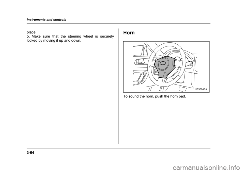
locked by moving it up and down.Horn
To sound the horn, push the horn pad.
UB3564BA
Page 236 of 627

4-1
4
Climate control
Ventilator ....................................................... 4-2 Air flow selection .............................................. 4-2
Center and side ventilators .............................. 4-3
Manual climate control system (if equipped) ............................................... 4-4Control panel ..................................................... 4-4
Heater operation ............................................... 4-7
Air conditioner operation ................................. 4-9
Automatic climate control system (if equipped) ............................................... 4-10Temperature sensors ....................................... 4-16
Operating tips for heater and air conditioner ........................................... 4-17Cleaning ventilator grille .................................. 4-17
Efficient cooling after parking in direct sunlight ........................................................... 4-18
Lubrication oil circulation in the refrigerant
circuit .............................................................. 4-18
Checking air conditioning system before summer season .................................. 4-18
Cooling and dehumidifying in high humidity and low temperature weather condition ...... 4-18
Air conditioner compressor shut-off
when engine is heavily loaded ...................... 4-18
Refrigerant for your climate control system .. 4-18
Air filtration system (if equipped) ................ 4-19
Page 237 of 627
4-2
Climate control
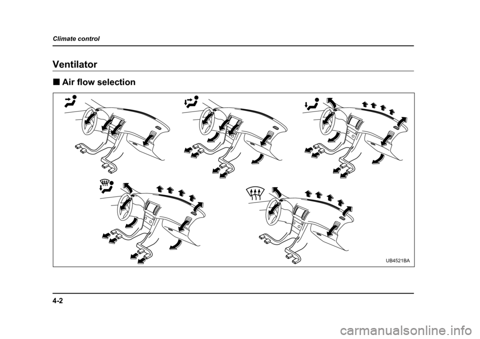
Climate controlVentilator !
Air flow selection
UB4521BA
Page 238 of 627
4-3
Climate control
– CONTINUED –
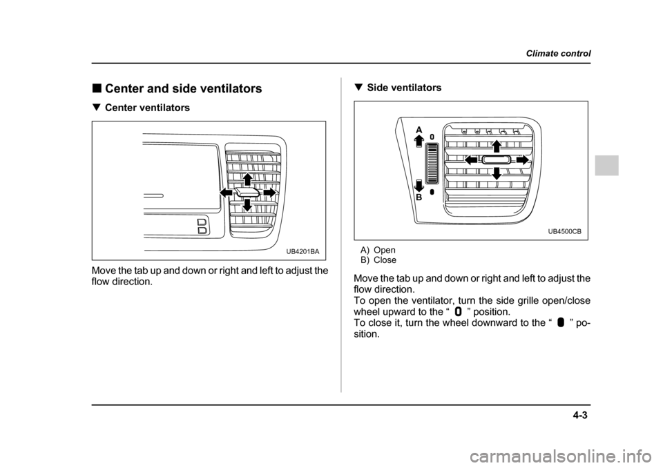
!Center and side ventilators
! Center ventilators
Move the tab up and down or right and left to adjust the
flow direction. !
Side ventilators
A) Open
B) Close
Move the tab up and down or right and left to adjust the
flow direction.
To open the ventilator, turn the side grille open/close
wheel upward to the “ ” position.
To close it, turn the wheel downward to the “ ” po-sition.
UB4201BA
A B
UB4500CB
Page 239 of 627
4-4
Climate control
Manual climate control system (if
equipped) !
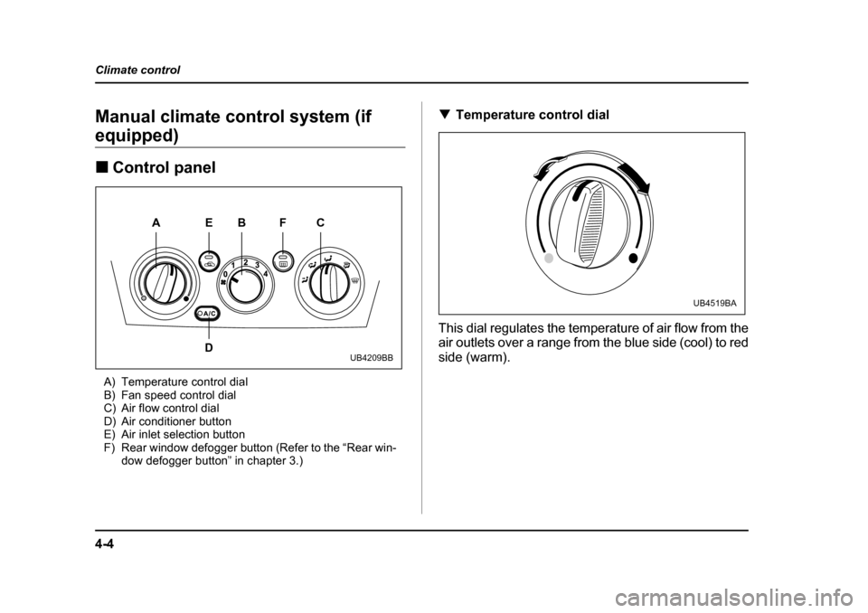
Control panel
A) Temperature control dial
B) Fan speed control dial
C) Air flow control dial
D) Air conditioner button
E) Air inlet selection button
F) Rear window defogger button (Refer to the “Rear win- dow defogger button” in chapter 3.) !
Temperature control dial
This dial regulates the temperature of air flow from the
air outlets over a range from the blue side (cool) to red side (warm).
AB F
E
D C
UB4209BB
UB4519BA
Page 240 of 627
4-5
Climate control
– CONTINUED –
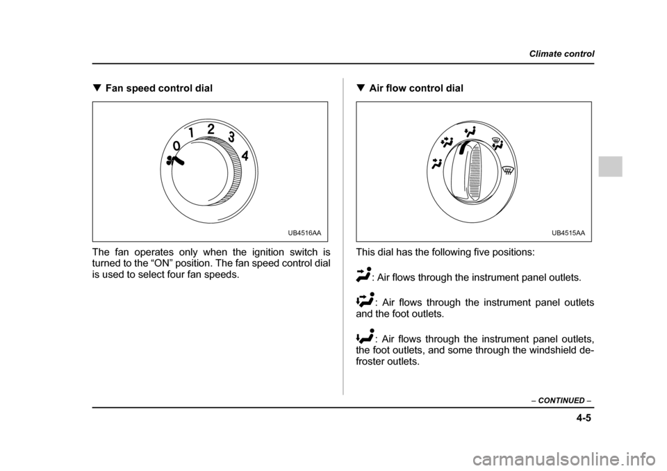
!Fan speed control dial
The fan operates only when the ignition switch is
turned to the “ON” position. The fan speed control dial
is used to select four fan speeds. !
Air flow control dial
This dial has the following five positions: : Air flows through the instrument panel outlets.: Air flows through the instrument panel outlets
and the foot outlets.
: Air flows through the instrument panel outlets,
the foot outlets, and some through the windshield de-
froster outlets.
UB4516AAUB4515AA