SUBARU OUTBACK 2007 4.G Owners Manual
Manufacturer: SUBARU, Model Year: 2007, Model line: OUTBACK, Model: SUBARU OUTBACK 2007 4.GPages: 442, PDF Size: 13.39 MB
Page 121 of 442

————————————————————————————————————————
————————————————————————————————————————
————————————————————————————————————————
————————————————————————————————————————
————————————————————————————————————————
————————————————————————————————————————
————————————————————————————————————————
————————————————————————————————————————
————————————————————————————————————————
————————————————————————————————————————
————————————————————————————————————————
————————————————————————————————————————
————————————————————————————————————————
Page 122 of 442

Ignition switch..................................................... 3-3
LOCK .................................................................. 3-3
ACC.................................................................... 3-4
ON...................................................................... 3-4
START ................................................................ 3-4
Key reminder chime ............................................ 3-5
Ignition switch light ............................................. 3-5
Hazard warning flasher ....................................... 3-5
Meters and gauges (Turbo models) ................... 3-5
Combination meter illumination ........................... 3-5
Speedometer ....................................................... 3-6
Tachometer ......................................................... 3-6
Fuel gauge .......................................................... 3-6
Temperature gauge ............................................. 3-7
ECO gauge ......................................................... 3-8
Multi-information display (Turbo models) .......... 3-8
Odometer and trip meter ..................................... 3-9
Current and average fuel consumption ............... 3-10
Outside temperature and journey time ................ 3-11
Driving range on remaining fuel .......................... 3-13
Clock (Vehicle with Navigation System) ............... 3-14
SI-DRIVE display ................................................ 3-14
Warning messages and driver ’s
information ...................................................... 3-15
Meters and gauges (Non-turbo models) ........... 3-18
Combination meter illumination .......................... 3-18
Canceling the function for meter/gauge needle movement upon turning on the ignition switch .............................................................. 3-18
Speedometer ...................................................... 3-18
Odometer ........................................................... 3-19 Double trip meter
............................................... 3-19
Tachometer ....................................................... 3-20
Fuel gauge ........................................................ 3-20
Temperature gauge ............................................ 3-21
Warning and indicator lights ............................. 3-22
Seatbelt warning light and chime ....................... 3-22
SRS airbag system warning light ........................ 3-24
Front passenger ’s frontal airbag ON and OFF
indicators ........................................................ 3-25
CHECK ENGINE warning light/Malfunction indicator lamp ................................................. 3-25
Charge warning light .......................................... 3-26
Oil pressure warning light .................................. 3-26
AT OIL TEMPerature warning light (AT vehicles) .................................................... 3-26
Low tire pressure warning light (if equipped) .................................................... 3-26
ABS warning light .............................................. 3-28
Brake system warning light ................................ 3-28
Low fuel warning light ....................................... 3-29
Door open warning light .................................... 3-29
All-Wheel Drive warning light (AT vehicles) .................................................... 3-30
Vehicle Dynamics Control operation indicator light (if equipped). ............................................ 3-30
Vehicle Dynamics Control warning light (if equipped)/Vehicle Dynamics Control OFF
indicator light (if equipped) .............................. 3-30
Security indicator light ....................................... 3-31
SPORT mode indicator light (if equipped) ........... 3-32
Shift-up indicator light (MT vehicles) (if equipped) .................................................... 3-32
Instruments and controls
3
Page 123 of 442

Instruments and controlsSelector lever position indicator (AT vehicles)(if equipped) ..................................................... 3-32
Gear position indicator (AT vehicles) (if equipped) ..................................................... 3-32
Selector lever and gear position indicator (AT vehicles) (if equipped) ...................................... 3-33
Turn signal indicator lights ................................. 3-33
High beam indicator light ................................... 3-33
Cruise control indicator light .............................. 3-33
Cruise control set indicator light ......................... 3-33
Headlight indicator light ..................................... 3-33
Front fog light indicator light .............................. 3-33
Clock (Vehicle without Navigation System) ............................................................ 3-34
Information display (Non-turbo models without Navigation System) ........................... 3-34
Outside temperature indicator ............................ 3-35
Current fuel consumption ................................... 3-36
Average fuel consumption .................................. 3-36
Driving range on remaining fuel .......................... 3-37
Journey time ...................................................... 3-38
Light control switch ........................................... 3-39
Headlights. ......................................................... 3-39 High/low beam change (dimmer) ...
..................... 3-39
Headlight flasher ............................................... 3-40
Daytime running light system ............................. 3-40
Turn signal lever ................................................ 3-41
Illumination brightness control ......................... 3-41
Parking light switch ........................................... 3-42
Front fog light switch (if equipped) .................. 3-42
Wiper and washer .............................................. 3-43
Windshield wiper and washer switches .............. 3-44
Rear window wiper and washer switch (Station wagon) ............................................... 3-45
Windshield wiper deicer (if equipped) .............. 3-46
Rear window defogger button .......................... 3-47
Mirrors ................................................................ 3-48
Inside mirror ...................................................... 3-48
Auto-dimming mirror/compass (if equipped) .................................................... 3-48
Outside mirrors ................................................. 3-50
Tilt steering wheel ............................................. 3-51
Horn .................................................................... 3-52
Page 124 of 442

Ignition switch
WARNING
. Never turn the ignition switch to
“ LOCK ”while the vehicle is
being driven or towed because
that will lock the steering wheel,
preventing steering control. And
when the engine is turned off, it
takes a much greater effort than
usual to steer.
. Before leaving the vehicle, al-
ways remove the key from the
ignition switch for safety and
never allow an unattended child
to remain in the vehicle. Failure
to follow this procedure could
result in injury to a child or
others. Children could operate
the power windows, the sunroof
or other controls or even make
the vehicle move.
CAUTION
Do not attach a large key holder or
key case to either key. If it banged
against your knees or hands while
you were driving, it could turn the
ignition switch from the “ON ”posi- tion to the
“Acc ”or “LOCK ”posi-
tion, thereby stopping the engine.
Also, if the key is attached to a
keyholder or to a large bunch of
other keys, centrifugal force may act
on it as the vehicle moves, resulting
in unwanted turning of the ignitionswitch.
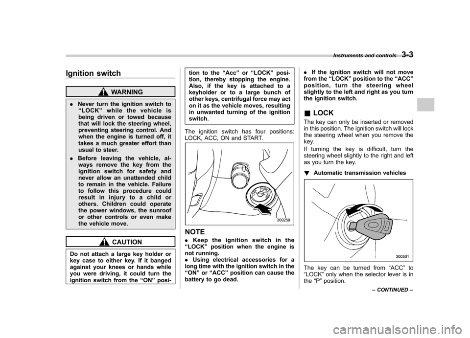
The ignition switch has four positions:
LOCK, ACC, ON and START.
NOTE . Keep the ignition switch in the
“ LOCK ”position when the engine is
not running. . Using electrical accessories for a
long time with the ignition switch in the“ ON ”or “ACC ”position can cause the
battery to go dead. .
If the ignition switch will not move
from the “LOCK ”position to the “ACC ”
position, turn the steering wheel
slightly to the left and right as you turn
the ignition switch.
& LOCK
The key can only be inserted or removed
in this position. The ignition switch will lock
the steering wheel when you remove the
key.
If turning the key is difficult, turn the
steering wheel slightly to the right and left
as you turn the key. ! Automatic transmission vehicles
The key can be turned from “ACC ”to
“ LOCK ”only when the selector lever is in
the “P ”position. Instruments and controls
3-3
– CONTINUED –
Page 125 of 442

3-4Instruments and controls
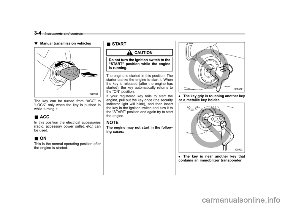
!Manual transmission vehicles
The key can be turned from “ACC ”to
“ LOCK ”only when the key is pushed in
while turning it.
& ACC
In this position the electrical accessories
(radio, accessory power outlet, etc.) can
be used. & ON
This is the normal operating position after
the engine is started. &
START
CAUTION
Do not turn the ignition switch to the “ START ”position while the engine
is running.
The engine is started in this position. The
starter cranks the engine to start it. When
the key is released (after the engine has
started), the key automatically returns to the “ON ”position.
If your registered key fails to start the
engine, pull out the key once (the security
indicator light will blink), and then insert
the key in the ignition switch and turn it tothe “START ”position and again try to start
the engine.
NOTE
The engine may not start in the follow-
ing cases:
. The key grip is touching another key
or a metallic key holder.
. The key is near another key that
contains an immobilizer transponder.
Page 126 of 442

&Key reminder chime
The reminder chime sounds when the driver ’s door opens and the key is in the
“ LOCK ”or “ACC ”positions. The chime
stops when the key is removed from the
ignition switch.
& Ignition switch light
For easy access to the ignition switch in
the dark, the ignition switch light comes on
when any of the doors are opened. The
light remains on for a several seconds and
gradually goes out after all doors are
closed or if the key is inserted in the
ignition switch. Hazard warning flasher
The hazard warning flasher is used to
warn other drivers when you have to park
your vehicle under emergency conditions.
The hazard warning flasher works with the
ignition switch in any position.
To turn on the hazard warning flasher,
push the hazard warning button on the
instrument panel. To turn off the flasher,
push the button again. NOTE
When the hazard warning flasher is on,
the turn signals do not work.Meters and gauges (Turbo
models) NOTE
Liquid-crystal displays are used in
some of the meters and gauges in the
combination meter. You will find their
indications hard to see if you wear
polarized glasses. &
Combination meter illumina- tion
When the ignition switch is turned to the “ ON ”position, the various parts of the
combination meter are illuminated in the
following sequence:
1. Meter needles, gauge needles and
multi-information display (if equipped) lightup.
2. Meter needles and gauge needles
each show MAX position.
3. Meter needles and gauge needles
each show MIN position.
4. Dials in meters and gauges light up.
5. Regular illumination (for driving) be- gins. Instruments and controls
3-5
– CONTINUED –
Page 127 of 442

3-6Instruments and controls
&Speedometer
The speedometer shows the vehicle speed. & Tachometer
The tachometer shows the engine speed
in thousands of revolutions per minute.
CAUTION
Do not operate the engine with the
pointer of the tachometer in the red
zone. In this range, fuel injection will
be cut by the engine control module
to protect the engine from overrev-
ving. The engine will resume run-
ning normally after the engine speed
is reduced below the red zone. &
Fuel gauge
The fuel gauge shows the approximate
amount of fuel remaining in the tank.
When the ignition switch is in the “LOCK ”
or “ACC ”position, the fuel gauge shows
“ E ”even if the fuel tank contains fuel.
The gauge may move slightly during
braking, turning or acceleration due to fuel
level movement in the tank.
If you press the trip knob while the ignition
switch is in the “LOCK ”position, the fuel
gauge ’s dial, needle, and rim will light up
and the needle will indicate the amount of
fuel remaining in the tank.
If, while the fuel gauge needle is indicating
the amount of fuel remaining in the tank,
you (a) do not press the trip knob for 10
seconds or (b) open and close the driver ’s door, the fuel gauge needle will drop to the“
E ” position and the dial, needle, and rim
will go off.
The rim of the fuel gauge flashes five
times when the amount of remaining fuel
reaches 2.6 US gal (10 liters, 2.2 lmp gal).
If you turn the ignition switch to the “ LOCK ”position and back to the “ON ”
position, the rim will again flash five times.
Page 128 of 442

NOTE
You will see the“”sign in the fuel
gauge.
This indicates that the fuel filler door
(lid) is located on the right side of thevehicle. ! Low fuel warning light
The low fuel warning light comes on when
the tank is nearly empty [Approximately
2.6 US gal (10 liters, 2.2 lmp gal)].
It only operates when the ignition switch is
in the “ON ”position.
NOTE
This light does not go out unless the
tank is replenished up to an internal fuel quantity of approximately 4.0 US
gal (15 liters, 3.3 lmp gal).
CAUTION
Promptly put fuel in the tank when-
ever the low fuel warning light
comes on. Engine misfires as a
result of an empty tank could cause
damage to the engine.
& Temperature gauge
1) Normal operating range
2) S# PREP indicator light
The temperature gauge shows engine
coolant temperature when the ignition
switch is in the “ON ”position. The coolant temperature will vary in
accordance with the outside temperature
and driving conditions.
We recommend that you drive moderately
until the pointer of the temperature gauge
reaches near the middle of the range.
Engine operation is optimum with the
engine coolant at this temperature range
and high revving operation when the
engine is not warmed up enough should
be avoided.
When the engine is not warmed up
sufficiently, the S# PREP indicator light
turns on. While this indicator light is on,
the SI-DRIVE mode cannot be changed to
the Sport Sharp (S#) mode. For details
about the SI-DRIVE mode, refer to the
“SI-
DRIVE (Turbo models) ”section in chapter
7.
CAUTION
If the pointer exceeds the normal
operating range, safely stop the
vehicle as soon as possible.
See the “In case of emergency ”in
chapter 9. Instruments and controls
3-7
– CONTINUED –
Page 129 of 442

3-8Instruments and controls
&ECO gauge
The ECO gauge shows the difference
between the average rate of fuel con-
sumption and the current rate of fuel
consumption. Using the average rate of
fuel consumption since the trip meter was
last reset, if the current rate of fuel
consumption is higher than the average
rate of fuel consumption, the indicator
needle points to the “+ ” or right side, and if
the current rate of fuel consumption is
lower than the average rate of fuel
consumption, the indicator needle points
to the “� ” or left side. When the indicator
needle is pointing to the “+ ” or right side, it
indicates fuel-efficient driving. NOTE .
The ECO gauge shows only an
approximate indication. . After resetting the trip meter, the
average rate of fuel consumption is not
shown until driving 0.6 mile (1 km).
Until that time, the ECO gauge does notoperate. Multi-information display
(Turbo models)
CAUTION
To ensure safety, do not attempt to
change the function of the indicator
during driving, as an accident couldresult.
1) Multi-information display
2) Multi-information display toggle button
With the ignition switch in the “ON ”
position, each successive push of the
multi-information display toggle button
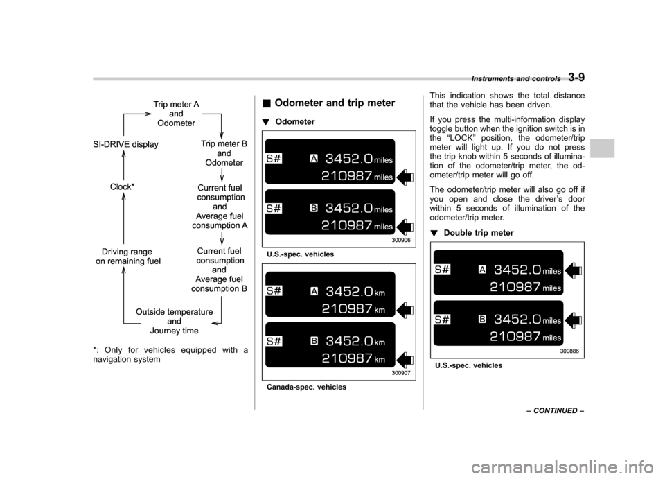
changes the display in the followingsequence:
Page 130 of 442

*: Only for vehicles equipped with a
navigation system&
Odometer and trip meter
! Odometer
U.S.-spec. vehicles
Canada-spec. vehicles This indication shows the total distance
that the vehicle has been driven.
If you press the multi-information display
toggle button when the ignition switch is in
the
“LOCK ”position, the odometer/trip
meter will light up. If you do not press
the trip knob within 5 seconds of illumina-
tion of the odometer/trip meter, the od-
ometer/trip meter will go off.
The odometer/trip meter will also go off if
you open and close the driver ’s door
within 5 seconds of illumination of the
odometer/trip meter. ! Double trip meter
U.S.-spec. vehicles Instruments and controls
3-9
– CONTINUED –