ECO mode SUBARU OUTBACK 2007 4.G User Guide
[x] Cancel search | Manufacturer: SUBARU, Model Year: 2007, Model line: OUTBACK, Model: SUBARU OUTBACK 2007 4.GPages: 442, PDF Size: 13.39 MB
Page 82 of 442
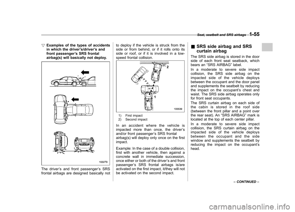
!Examples of the types of accidents
in which the driver ’s/driver ’s and
front passenger ’s SRS frontal
airbag(s) will basically not deploy.
The driver ’s and front passenger ’s SRS
frontal airbags are designed basically not to deploy if the vehicle is struck from the
side or from behind, or if it rolls onto its
side or roof, or if it is involved in a low-
speed frontal collision.
1) First impact
2) Second impact
In an accident where the vehicle is
impacted more than once, the driver ’s
and/or front passenger ’s SRS frontal
airbag(s) will deploy only once on the firstimpact.
Example: In the case of a double collision,
first with another vehicle, then against a
concrete wall in immediate succession,
once either or both of the driver ’s and front
passenger ’s SRS frontal airbags is/are
activated on the first impact, it/they will not
be activated on the second impact. &
SRS side airbag and SRS
curtain airbag
The SRS side airbag is stored in the door
side of each front seat seatback, which
bears an “SRS AIRBAG ”label.
Inamoderatetoseveresideimpact
collision, the SRS side airbag on the
impacted side of the vehicle deploys
between the occupant and the door panel
and supplements the seatbelt by reducing
the impact on the occupant ’s chest and
waist. The SRS side airbag operates only
for front seat occupants.
The SRS curtain airbag on each side of
the cabin is stored in the roof side
(between the front pillar and a point over
the rear seat). An “SRS AIRBAG ”mark is
located at the top of each center pillar.
Inamoderatetoseveresideimpact
collision, the SRS curtain airbag on the
impacted side of the vehicle deploys
between the occupant and the side
window and supplements the seatbelt by
reducing the impact on the occupant ’s
head. Seat, seatbelt and SRS airbags
1-55
– CONTINUED –
Page 88 of 442
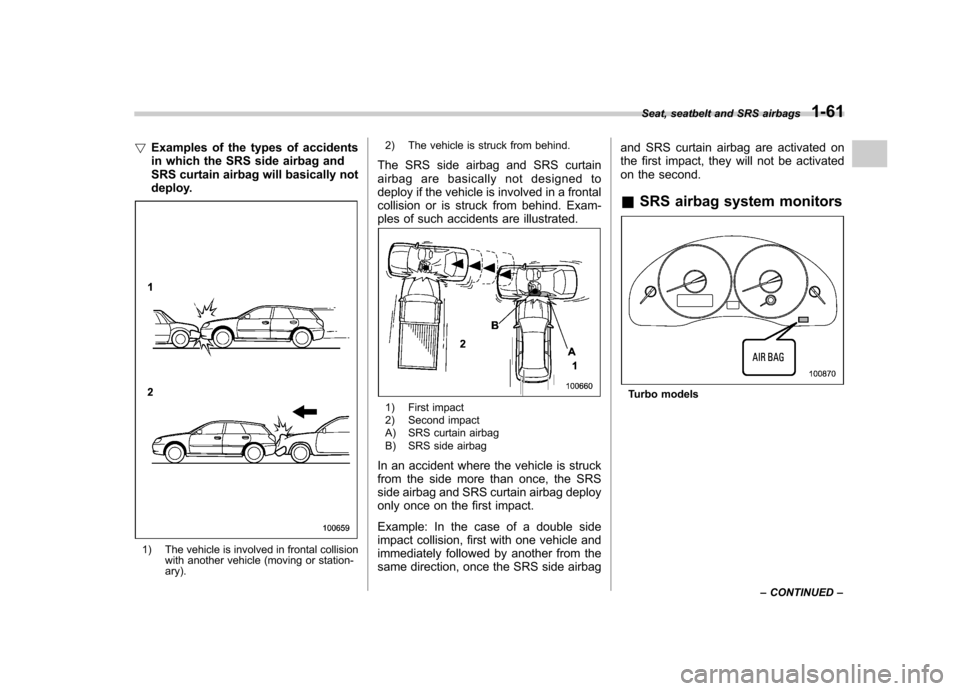
!Examples of the types of accidents
in which the SRS side airbag and
SRS curtain airbag will basically not
deploy.
1) The vehicle is involved in frontal collision
with another vehicle (moving or station- ary). 2) The vehicle is struck from behind.
The SRS side airbag and SRS curtain
airbag are basically not designed to
deploy if the vehicle is involved in a frontal
collision or is struck from behind. Exam-
ples of such accidents are illustrated.
1) First impact
2) Second impact
A) SRS curtain airbag
B) SRS side airbag
In an accident where the vehicle is struck
from the side more than once, the SRS
side airbag and SRS curtain airbag deploy
only once on the first impact.
Example: In the case of a double side
impact collision, first with one vehicle and
immediately followed by another from the
same direction, once the SRS side airbag and SRS curtain airbag are activated on
the first impact, they will not be activated
on the second. &
SRS airbag system monitorsTurbo modelsSeat, seatbelt and SRS airbags
1-61
– CONTINUED –
Page 89 of 442
1-62Seat, seatbelt and SRS airbags
Non-turbo models
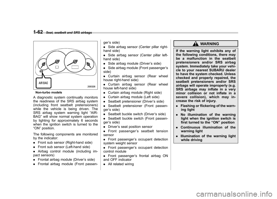
A diagnostic system continually monitors
the readiness of the SRS airbag system
(including front seatbelt pretensioners)
while the vehicle is being driven. The
SRS airbag system warning light “AIR-
BAG ”will show normal system operation
by lighting for approximately 6 seconds
when the ignition switch is turned to the“ ON ”position.
The following components are monitored
by the indicator: . Front sub sensor (Right-hand side)
. Front sub sensor (Left-hand side)
. Airbag control module (including im-
pact sensors). Frontal airbag module (Driver ’s side)
. Frontal airbag module (Front passen- ger
’s side)
. Side airbag sensor (Center pillar right-
hand side). Side airbag sensor (Center pillar left-
hand side). Side airbag module (Driver ’s side)
. Side airbag module (Front passenger ’s
side). Curtain airbag sensor (Rear wheel
house right-hand side). Curtain airbag sensor (Rear wheel
house left-hand side). Curtain airbag module (Right side)
. Curtain airbag module (Left side)
. Seatbelt pretensioner (Driver ’s side)
. Seatbelt pretensioner (Front passen-
ger ’s side)
. Seatbelt buckle switch (Driver ’s side)
. Seatbelt buckle switch (Front passen-
ger ’s side)
. Driver ’s seat position sensor
. Front passenger ’s seatbelt tension
sensor. Front passenger ’s occupant detection
system weight sensor. Front passenger ’s occupant detection
control module. Front passenger ’s frontal airbag ON
and OFF indicator. All related wiring
WARNING
If the warning light exhibits any of
the following conditions, there may
be a malfunction in the seatbelt
pretensioners and/or SRS airbag
system. Immediately take your vehi-
cle to your nearest SUBARU dealer
to have the system checked. Unless
checked and properly repaired, the
seatbelt pretensioners and/or SRS
airbags will operate improperly (e.g.
SRS airbags may inflate in a very
minor collision or not inflate in a
severe collision), which may in-
crease the risk of injury. . Flashing or flickering of the warn-
ing light
. No illumination of the warning
light when the ignition switch is
first turned to the “ON ”position
. Continuous illumination of the
warning light
. Illumination of the warning light
while driving
Page 95 of 442
2-4Keys and doors
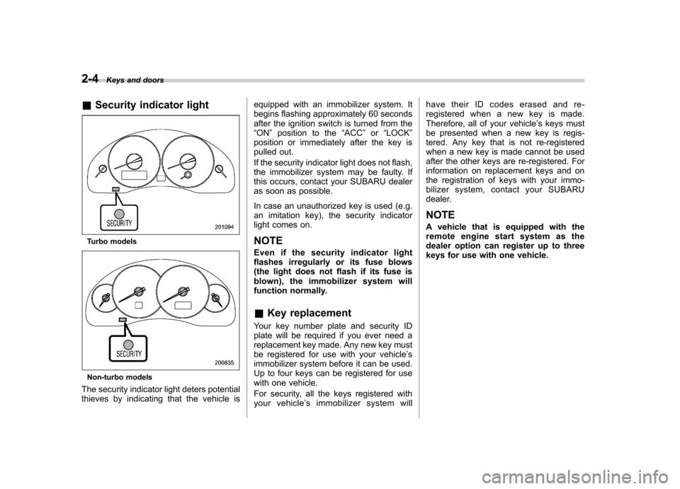
& Security indicator light
Turbo models
Non-turbo models
The security indicator light deters potential
thieves by indicating that the vehicle is equipped with an immobilizer system. It
begins flashing approximately 60 seconds
after the ignition switch is turned from the“
ON ”position to the “ACC ”or “LOCK ”
position or immediately after the key is
pulled out.
If the security indicator light does not flash,
the immobilizer system may be faulty. If
this occurs, contact your SUBARU dealer
as soon as possible.
In case an unauthorized key is used (e.g.
an imitation key), the security indicator
light comes on.
NOTE
Even if the security indicator light
flashes irregularly or its fuse blows
(the light does not flash if its fuse is
blown), the immobilizer system will
function normally. & Key replacement
Your key number plate and security ID
plate will be required if you ever need a
replacement key made. Any new key must
be registered for use with your vehicle ’s
immobilizer system before it can be used.
Up to four keys can be registered for use
with one vehicle.
For security, all the keys registered with
your vehicle ’s immobilizer system will have their ID codes erased and re-
registered when a new key is made.
Therefore, all of your vehicle
’s keys must
be presented when a new key is regis-
tered. Any key that is not re-registered
when a new key is made cannot be used
after the other keys are re-registered. For
information on replacement keys and on
the registration of keys with your immo-
bilizer system, contact your SUBARU
dealer.
NOTE
A vehicle that is equipped with the
remote engine start system as the
dealer option can register up to three
keys for use with one vehicle.
Page 106 of 442

.Opening a door, the rear gate or trunk
lid . Physical impact to the vehicle, such as
forced entry (only vehicles with shock
sensors (dealer option)) & Activating and deactivating
the alarm system
To change the setting of your vehicle ’s
alarm system for activation or deactiva-
tion, do the following.
1. Disarm the alarm system (see “Dis-
arming the system ”in this section).
2. Sit in the driver ’s seat and shut all
doors (and the rear gate if your vehicle is a
Station wagon).
3. Turn the ignition switch to the “ON ”
position.
4. Hold down the UNLOCK side of the driver ’s power door locking switch, open
the driver ’s door within the following 1
second, and wait 10 seconds without
releasing the switch. The setting will then
be changed as follows:
If the system was previously activated:
For non-turbo models, the odometer/trip
meter screen displays “AL oF ”, and for
turbo models, the multi-information displayshows “Security alarm: OFF ”and the horn
sounds twice, indicating that the system is
now deactivated. If the system was previously deactivated:
For non-turbo models, the odometer/trip
meter screen displays
“AL on ”, and for
turbo models, the multi-information displayshows “Security alarm: ON ”and the horn
sounds once, indicating that the system is
now deactivated.
NOTE
You may have the above setting
change done by your SUBARU dealer. & If you have accidentally trig-
gered the alarm system
! To stop the alarm
Do any of the following operations: . Insert the key in the door lock of the
driver ’s door and turn it to the unlock
position.. Press any button on the remote trans-
mitter.. Turn the ignition switch to the “ON ”
position.
& Arming the system
! To arm the system using remote transmitter
1. Close all windows and the moonroof (if
so equipped). 2. Remove the key from the ignitionswitch.
3. Open the doors and get out of the vehicle.
4. Make sure that the engine hood (and
the trunk lid on the Sedan) are locked.
5. Close all doors (and the rear gate on
the Station wagon).
: Press to Arm the system.: Press to Disarm the system.
Keys and doors
2-15
– CONTINUED –
Page 107 of 442
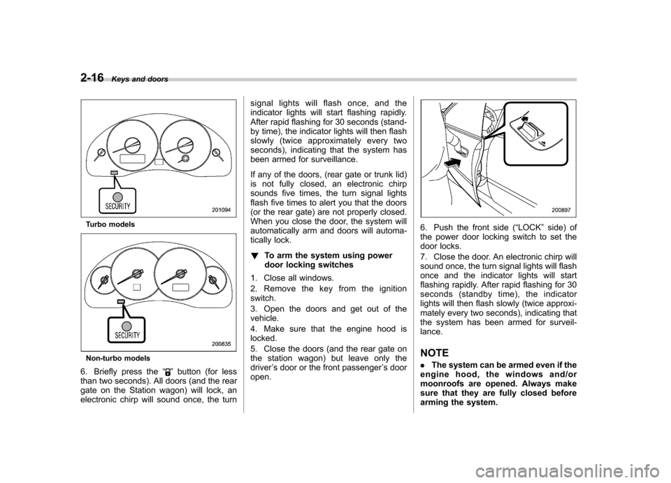
2-16Keys and doors
Turbo models
Non-turbo models
6. Briefly press the “
”button (for less
than two seconds). All doors (and the rear
gate on the Station wagon) will lock, an
electronic chirp will sound once, the turn signal lights will flash once, and the
indicator lights will start flashing rapidly.
After rapid flashing for 30 seconds (stand-
by time), the indicator lights will then flash
slowly (twice approximately every two
seconds), indicating that the system has
been armed for surveillance.
If any of the doors, (rear gate or trunk lid)
is not fully closed, an electronic chirp
sounds five times, the turn signal lights
flash five times to alert you that the doors
(or the rear gate) are not properly closed.
When you close the door, the system will
automatically arm and doors will automa-
tically lock. !
To arm the system using power
door locking switches
1. Close all windows.
2. Remove the key from the ignition switch.
3. Open the doors and get out of the vehicle.
4. Make sure that the engine hood is locked.
5. Close the doors (and the rear gate on
the station wagon) but leave only thedriver ’s door or the front passenger ’s door
open.
6. Push the front side ( “LOCK ”side) of
the power door locking switch to set the
door locks.
7. Close the door. An electronic chirp will
sound once, the turn signal lights will flash
once and the indicator lights will start
flashing rapidly. After rapid flashing for 30
seconds (standby time), the indicator
lights will then flash slowly (twice approxi-
mately every two seconds), indicating that
the system has been armed for surveil-lance. NOTE . The system can be armed even if the
engine hood, the windows and/or
moonroofs are opened. Always make
sure that they are fully closed before
arming the system.
Page 108 of 442

.The 30-second standby time can be
eliminated if you prefer. Have it per-
formed by your SUBARU dealer.. If your vehicle is a Sedan and you
unlock the trunk using the remotetransmitter ’s “
”button with the
alarm system armed, the system will
be temporarily placed in a standby
state. The system will go back to the
surveillance state upon locking thetrunk.. The system is in the standby mode
for a 30-second period after locking the
doors with the remote transmitter. The
security indicator light will flash at
short intervals during this period. . If any of the following actions is
done during the standby period, the
system will not switch to the surveil-
lance state.
.Doors are unlocked using the
remote transmitter. . Any door (including the rear gate
of a Station wagon or the trunk of a
Sedan) is opened. . Ignition switch is turned to the
“ ON ”position. &
Disarming the system
Briefly press the “
”button (for less than
two seconds) on the remote transmitter.
The driver ’s door will unlock, an electronic
chirp will sound twice, the turn signal lights
will flash twice and the indicator light will
go off.
To unlock all other doors and the rear gate
(Station wagon), briefly press the “
”
button a second time within 5 seconds. NOTE
If the interval between the first and
second presses of the “
”button (for
unlocking of all of the doors and the
rear gate) is extremely short, the sys-
tem may not respond.
Or the system can be disarmed by the
following method, too. . Insert the key in the door lock of the
driver ’s door and turn it to the unlock
position. ! Emergency disarming
If you cannot disarm the system using the
transmitter (i.e. the transmitter is lost,
broken or the transmitter battery is too
weak), you can disarm the system without
using the transmitter.
The system can be disarmed if you turn
the ignition switch from the “LOCK ”to the “
ON ”position with a registered key.
Insert the key in the door lock of thedriver ’s door and turn it to the unlock
position.
& Valet mode
When you choose the valet mode, the
alarm system does not operate. In valet
mode, the remote transmitter is used only
for locking and unlocking the doors and
rear gate (Station wagon) and panicactivation.
To enter the valet mode, change the
setting of your vehicle ’s alarm system for
deactivation mode. (Refer to “Activating
and deactivating the alarm system ”in this
section.) The security indicator light will
continue to flash once every three sec-
onds indicating that the system is in the
valet mode.
To exit valet mode, change the setting of
your vehicle ’s alarm system for activation
mode. (Refer to “Activating and deactivat-
ing the alarm system ”in this section.)
& Passive arming
When passive arming mode has been
programmed by the dealer, arming of the
system is automatically accomplished
without using the remote transmitter. Note Keys and doors
2-17
– CONTINUED –
Page 122 of 442

Ignition switch..................................................... 3-3
LOCK .................................................................. 3-3
ACC.................................................................... 3-4
ON...................................................................... 3-4
START ................................................................ 3-4
Key reminder chime ............................................ 3-5
Ignition switch light ............................................. 3-5
Hazard warning flasher ....................................... 3-5
Meters and gauges (Turbo models) ................... 3-5
Combination meter illumination ........................... 3-5
Speedometer ....................................................... 3-6
Tachometer ......................................................... 3-6
Fuel gauge .......................................................... 3-6
Temperature gauge ............................................. 3-7
ECO gauge ......................................................... 3-8
Multi-information display (Turbo models) .......... 3-8
Odometer and trip meter ..................................... 3-9
Current and average fuel consumption ............... 3-10
Outside temperature and journey time ................ 3-11
Driving range on remaining fuel .......................... 3-13
Clock (Vehicle with Navigation System) ............... 3-14
SI-DRIVE display ................................................ 3-14
Warning messages and driver ’s
information ...................................................... 3-15
Meters and gauges (Non-turbo models) ........... 3-18
Combination meter illumination .......................... 3-18
Canceling the function for meter/gauge needle movement upon turning on the ignition switch .............................................................. 3-18
Speedometer ...................................................... 3-18
Odometer ........................................................... 3-19 Double trip meter
............................................... 3-19
Tachometer ....................................................... 3-20
Fuel gauge ........................................................ 3-20
Temperature gauge ............................................ 3-21
Warning and indicator lights ............................. 3-22
Seatbelt warning light and chime ....................... 3-22
SRS airbag system warning light ........................ 3-24
Front passenger ’s frontal airbag ON and OFF
indicators ........................................................ 3-25
CHECK ENGINE warning light/Malfunction indicator lamp ................................................. 3-25
Charge warning light .......................................... 3-26
Oil pressure warning light .................................. 3-26
AT OIL TEMPerature warning light (AT vehicles) .................................................... 3-26
Low tire pressure warning light (if equipped) .................................................... 3-26
ABS warning light .............................................. 3-28
Brake system warning light ................................ 3-28
Low fuel warning light ....................................... 3-29
Door open warning light .................................... 3-29
All-Wheel Drive warning light (AT vehicles) .................................................... 3-30
Vehicle Dynamics Control operation indicator light (if equipped). ............................................ 3-30
Vehicle Dynamics Control warning light (if equipped)/Vehicle Dynamics Control OFF
indicator light (if equipped) .............................. 3-30
Security indicator light ....................................... 3-31
SPORT mode indicator light (if equipped) ........... 3-32
Shift-up indicator light (MT vehicles) (if equipped) .................................................... 3-32
Instruments and controls
3
Page 126 of 442

&Key reminder chime
The reminder chime sounds when the driver ’s door opens and the key is in the
“ LOCK ”or “ACC ”positions. The chime
stops when the key is removed from the
ignition switch.
& Ignition switch light
For easy access to the ignition switch in
the dark, the ignition switch light comes on
when any of the doors are opened. The
light remains on for a several seconds and
gradually goes out after all doors are
closed or if the key is inserted in the
ignition switch. Hazard warning flasher
The hazard warning flasher is used to
warn other drivers when you have to park
your vehicle under emergency conditions.
The hazard warning flasher works with the
ignition switch in any position.
To turn on the hazard warning flasher,
push the hazard warning button on the
instrument panel. To turn off the flasher,
push the button again. NOTE
When the hazard warning flasher is on,
the turn signals do not work.Meters and gauges (Turbo
models) NOTE
Liquid-crystal displays are used in
some of the meters and gauges in the
combination meter. You will find their
indications hard to see if you wear
polarized glasses. &
Combination meter illumina- tion
When the ignition switch is turned to the “ ON ”position, the various parts of the
combination meter are illuminated in the
following sequence:
1. Meter needles, gauge needles and
multi-information display (if equipped) lightup.
2. Meter needles and gauge needles
each show MAX position.
3. Meter needles and gauge needles
each show MIN position.
4. Dials in meters and gauges light up.
5. Regular illumination (for driving) be- gins. Instruments and controls
3-5
– CONTINUED –
Page 128 of 442

NOTE
You will see the“”sign in the fuel
gauge.
This indicates that the fuel filler door
(lid) is located on the right side of thevehicle. ! Low fuel warning light
The low fuel warning light comes on when
the tank is nearly empty [Approximately
2.6 US gal (10 liters, 2.2 lmp gal)].
It only operates when the ignition switch is
in the “ON ”position.
NOTE
This light does not go out unless the
tank is replenished up to an internal fuel quantity of approximately 4.0 US
gal (15 liters, 3.3 lmp gal).
CAUTION
Promptly put fuel in the tank when-
ever the low fuel warning light
comes on. Engine misfires as a
result of an empty tank could cause
damage to the engine.
& Temperature gauge
1) Normal operating range
2) S# PREP indicator light
The temperature gauge shows engine
coolant temperature when the ignition
switch is in the “ON ”position. The coolant temperature will vary in
accordance with the outside temperature
and driving conditions.
We recommend that you drive moderately
until the pointer of the temperature gauge
reaches near the middle of the range.
Engine operation is optimum with the
engine coolant at this temperature range
and high revving operation when the
engine is not warmed up enough should
be avoided.
When the engine is not warmed up
sufficiently, the S# PREP indicator light
turns on. While this indicator light is on,
the SI-DRIVE mode cannot be changed to
the Sport Sharp (S#) mode. For details
about the SI-DRIVE mode, refer to the
“SI-
DRIVE (Turbo models) ”section in chapter
7.
CAUTION
If the pointer exceeds the normal
operating range, safely stop the
vehicle as soon as possible.
See the “In case of emergency ”in
chapter 9. Instruments and controls
3-7
– CONTINUED –