oil SUBARU OUTBACK 2007 4.G Owners Manual
[x] Cancel search | Manufacturer: SUBARU, Model Year: 2007, Model line: OUTBACK, Model: SUBARU OUTBACK 2007 4.GPages: 442, PDF Size: 13.39 MB
Page 7 of 442
4
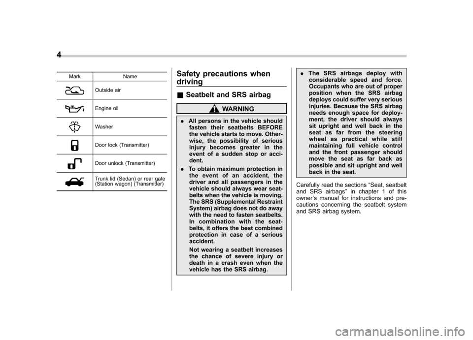
Mark Name
Outside air
Engine oil
Washer
Door lock (Transmitter)
Door unlock (Transmitter)
Trunk lid (Sedan) or rear gate
(Station wagon) (Transmitter)Safety precautions when driving &
Seatbelt and SRS airbag
WARNING
. All persons in the vehicle should
fasten their seatbelts BEFORE
the vehicle starts to move. Other-
wise, the possibility of serious
injury becomes greater in the
event of a sudden stop or acci-dent.
. To obtain maximum protection in
the event of an accident, the
driver and all passengers in the
vehicle should always wear seat-
belts when the vehicle is moving.
The SRS (Supplemental Restraint
System) airbag does not do away
with the need to fasten seatbelts.
In combination with the seat-
belts, it offers the best combined
protection in case of a seriousaccident.
Not wearing a seatbelt increases
the chance of severe injury or
death in a crash even when the
vehicle has the SRS airbag. .
The SRS airbags deploy with
considerable speed and force.
Occupants who are out of proper
position when the SRS airbag
deploys could suffer very serious
injuries. Because the SRS airbag
needs enough space for deploy-
ment, the driver should always
sit upright and well back in the
seat as far from the steering
wheel as practical while still
maintaining full vehicle control
and the front passenger should
move the seat as far back as
possible and sit upright and well
back in the seat.
Carefully read the sections “Seat, seatbelt
and SRS airbags ”in chapter 1 of this
owner ’s manual for instructions and pre-
cautions concerning the seatbelt system
and SRS airbag system.
Page 24 of 442

&Warning and indicator light
Mark Name Page
Seatbelt warning light 3-22
Front passenger ’s seat-
belt warning light 3-22
SRS airbag system warn-
ing light3-24
CHECK ENGINE warning
light/Malfunction indicator lamp3-25
Charge warning light 3-26
Oil pressure warning light 3-26
AT OIL temperature
warning light (if equipped)
3-26
orABS warning light 3-28
orBrake system warning light
3-28
orDoor open warning light 3-29 Mark Name Page
Low fuel warning light 3-29
All-Wheel Drive warning
light (if equipped)
3-30
Vehicle Dynamics Control
operation indicator light (if
equipped)3-30
Vehicle Dynamics Control
warning light/Vehicle Dy-
namics Control OFF indi-
cator light (if equipped)3-30
Security indicator light 3-31
Turn signal indicator lights 3-33
High beam indicator light 3-33
Cruise control indicator
light (if equipped)
3-33
Cruise control set indica-
tor light (if equipped)
3-33
Light indicator light 3-33
Low tire pressure warning
light (if equipped)3-26Mark Name Page
orPassenger airbag ON in-
dicator light
3-25
orPassenger airbag OFF
indicator light
3-25
SPORT mode indicator
light (if equipped)3-32
orDaytime running lights in-
dicator light3-40
Shift up indicator (MT ve-
hicles) (if equipped)
3-32
S# PREP indicator
(if equipped) 3-721
– CONTINUED –
Page 50 of 442
Sedan models
Wagon models
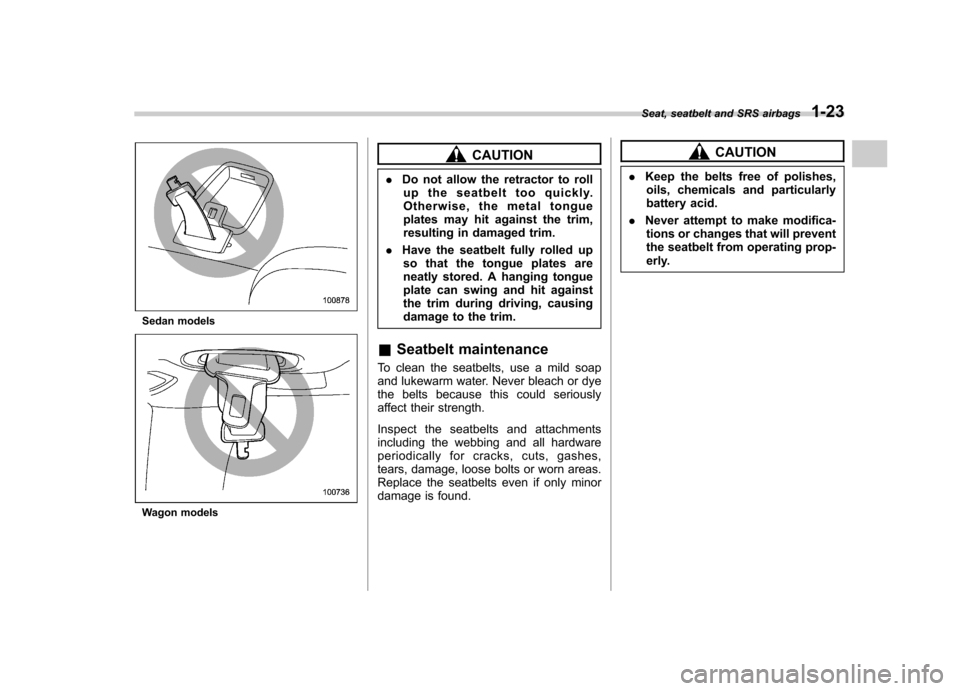
CAUTION
. Do not allow the retractor to roll
up the seatbelt too quickly.
Otherwise, the metal tongue
plates may hit against the trim,
resulting in damaged trim.
. Have the seatbelt fully rolled up
so that the tongue plates are
neatly stored. A hanging tongue
plate can swing and hit against
the trim during driving, causing
damage to the trim.
& Seatbelt maintenance
To clean the seatbelts, use a mild soap
and lukewarm water. Never bleach or dye
the belts because this could seriously
affect their strength.
Inspect the seatbelts and attachments
including the webbing and all hardware
periodically for cracks, cuts, gashes,
tears, damage, loose bolts or worn areas.
Replace the seatbelts even if only minor
damage is found.CAUTION
. Keep the belts free of polishes,
oils, chemicals and particularly
battery acid.
. Never attempt to make modifica-
tions or changes that will prevent
the seatbelt from operating prop-
erly.
Seat, seatbelt and SRS airbags
1-23
Page 101 of 442
2-10Keys and doors
when the “”button is pressed. This light
stays illuminated for approximately 30
seconds if any of the doors or the rear
gate (Station wagon) is not opened.
If the “
”button is pressed before 30
seconds have elapsed, this light will go
out. The interior light must be set to the
middle position in order for this function
to operate.
A SUBARU dealer can change the illumi-
nation period setting of the interior light in
accordance with your preference. Contact
the nearest SUBARU dealer for details. & Vehicle finder function
Use this function to find your vehicle
parked among many vehicles in a large
parking lot. Provided you are within 30 feet
(10 meters) of the vehicle, pressing the “
”
button three times in a five-second period
will cause your vehicle ’s horn to sound
once and its turn signal lights to flash threetimes.
NOTE
If the interval between presses is too
short when you press the “
”button
three times, the system may not re-
spond to the signals from the remote
transmitter. &
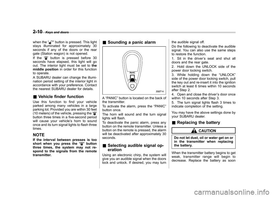
Sounding a panic alarm
A“PANIC ”button is located on the back of
the transmitter.
To activate the alarm, press the “PANIC ”
button once.
The horn will sound and the turn signal
lights will flash.
To deactivate the panic alarm, press any
button on the remote transmitter. Unless a
button on the remote is pressed, the alarm
will be deactivated after approximately 30seconds. & Selecting audible signal op- eration
Using an electronic chirp, the system will
give you an audible signal when the doors
lock and unlock. If desired, you may turn the audible signal off.
Do the following to deactivate the audible
signal. You can also use the same steps
to restore the function.
1. Sit in the driver
’s seat and shut all
doors and the rear gate.
2. Hold down the UNLOCK side of the
power door locking switch.
3. While holding down the “UNLOCK ”
side of the power door locking switch, pull
the key out and re-insert it into the ignition
switch at least 6 times within 10 seconds
after Step 2.
4. Open and close the driver ’s door once
within 10 seconds after Step 3.
5. The turn signal lights flash 3 times to
indicate completion of the setting.
You may have the above settings done by
your SUBARU dealer.
& Replacing the battery
CAUTION
Do not let dust, oil or water get on or
in the transmitter when replacing
the battery.
When the transmitter battery begins to get
weak, transmitter range will begin to
decrease. Replace the battery as soon
Page 122 of 442
Ignition switch..................................................... 3-3
LOCK .................................................................. 3-3
ACC.................................................................... 3-4
ON...................................................................... 3-4
START ................................................................ 3-4
Key reminder chime ............................................ 3-5
Ignition switch light ............................................. 3-5
Hazard warning flasher ....................................... 3-5
Meters and gauges (Turbo models) ................... 3-5
Combination meter illumination ........................... 3-5
Speedometer ....................................................... 3-6
Tachometer ......................................................... 3-6
Fuel gauge .......................................................... 3-6
Temperature gauge ............................................. 3-7
ECO gauge ......................................................... 3-8
Multi-information display (Turbo models) .......... 3-8
Odometer and trip meter ..................................... 3-9
Current and average fuel consumption ............... 3-10
Outside temperature and journey time ................ 3-11
Driving range on remaining fuel .......................... 3-13
Clock (Vehicle with Navigation System) ............... 3-14
SI-DRIVE display ................................................ 3-14
Warning messages and driver ’s
information ...................................................... 3-15
Meters and gauges (Non-turbo models) ........... 3-18
Combination meter illumination .......................... 3-18
Canceling the function for meter/gauge needle movement upon turning on the ignition switch .............................................................. 3-18
Speedometer ...................................................... 3-18
Odometer ........................................................... 3-19 Double trip meter
............................................... 3-19
Tachometer ....................................................... 3-20
Fuel gauge ........................................................ 3-20
Temperature gauge ............................................ 3-21
Warning and indicator lights ............................. 3-22
Seatbelt warning light and chime ....................... 3-22
SRS airbag system warning light ........................ 3-24
Front passenger ’s frontal airbag ON and OFF
indicators ........................................................ 3-25
CHECK ENGINE warning light/Malfunction indicator lamp ................................................. 3-25
Charge warning light .......................................... 3-26
Oil pressure warning light .................................. 3-26
AT OIL TEMPerature warning light (AT vehicles) .................................................... 3-26
Low tire pressure warning light (if equipped) .................................................... 3-26
ABS warning light .............................................. 3-28
Brake system warning light ................................ 3-28
Low fuel warning light ....................................... 3-29
Door open warning light .................................... 3-29
All-Wheel Drive warning light (AT vehicles) .................................................... 3-30
Vehicle Dynamics Control operation indicator light (if equipped). ............................................ 3-30
Vehicle Dynamics Control warning light (if equipped)/Vehicle Dynamics Control OFF
indicator light (if equipped) .............................. 3-30
Security indicator light ....................................... 3-31
SPORT mode indicator light (if equipped) ........... 3-32
Shift-up indicator light (MT vehicles) (if equipped) .................................................... 3-32
Instruments and controls
3
Page 143 of 442
3-22Instruments and controls
Warning and indicator lights
Several of the warning and indicator lights
come on momentarily and then go out
when the ignition switch is initially turned
to the“ON ”position. This permits check-
ing the operation of the bulbs.
Apply the parking brake and turn the
ignition switch to the “ON ”position. The
following lights come on:
: Seatbelt warning light
(The seatbelt warning light goes out only
when the driver fastens the seatbelt.)
: Front passenger ’s seatbelt warning
light
(The seatbelt warning light goes out only
when the front seat passenger fastens theseatbelt.)
: SRS airbag system warning light
: CHECK ENGINE warning light/Mal- function indicator lamp
: Charge warning light
: Oil pressure warning light
: AT OIL temperature warning light (ATvehicles)
/: ABS warning light
: Vehicle Dynamics Control operation indicator light (if equipped)
: Vehicle Dynamics Control warning light
(if equipped)/Vehicle Dynamics Control
OFF indicator light (if equipped)
/: Brake system warning light
: AWD warning light (AT vehicles)
: Low tire pressure warning light (if equipped)
: SPORT mode indicator light (AT vehicles)
/: Front passenger ’s frontal airbag
ON indicator light
/: Front passenger ’s frontal airbag
OFF indicator light
: Low fuel warning light
/: Door open warning light
: Cruise control indicator light (if equipped)
: Cruise control set indicator light (if
equipped)
: Shift-up indicator light (MT vehicles) (ifequipped)
: S# PREP indicator light (if equipped)
If any lights fail to come on, it indicates a burned-out bulb or a malfunction of the
corresponding system.
Consult your authorized SUBARU dealer
for repair.
& Seatbelt warning light
and chime
Your vehicle is equipped with a seatbelt
warning device at the driver ’s and front
passenger ’s seat, as required by current
safety standards.
With the ignition switch turned to the “ON ”
position, this device reminds the driver
and front passenger to fasten their seat-
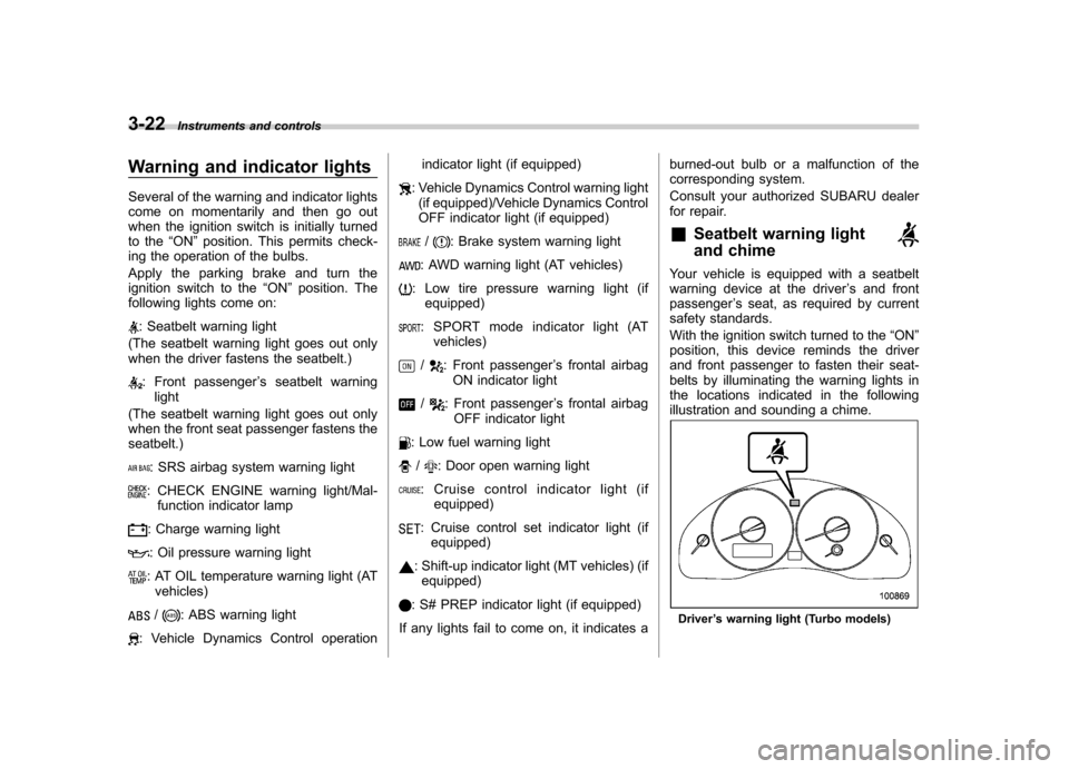
belts by illuminating the warning lights in
the locations indicated in the following
illustration and sounding a chime.
Driver ’s warning light (Turbo models)
Page 147 of 442

3-26Instruments and controls
turn off immediately. It may take several
driving trips. If the light does not go out,
take your vehicle to your authorized
SUBARU dealer immediately. !If the light is blinking:
If the light is blinking while driving, an
engine misfire condition has been de-
tected which may damage the emission
control system.
To prevent serious damage to the emis-
sion control system, you should do thefollowing. . Reduce vehicle speed.
. Avoid hard acceleration.
. Avoid steep uphill grades.
. Reduce the amount of cargo, if possi-
ble.. Stop towing a trailer as soon as
possible.
The CHECK ENGINE warning light/mal-
function indicator lamp may stop blinking
and come on steadily after several driving
trips. You should have your vehicle
checked by an authorized SUBARU deal-
er immediately. & Charge warning light
If this light comes on when the engine is
running, it may indicate that the charging system is not working properly.
If the light comes on while driving or does
not go out after the engine starts, stop the
engine at the first safe opportunity and
check the alternator belt. If the belt is
loose, broken or if the belt is in good
condition but the light remains on, contact
your nearest SUBARU dealer immedi-
ately.
& Oil pressure warning light
CAUTION
Do not operate the engine with the
oil pressure warning light on. This
may cause serious engine damage.
If this light comes on when the engine is
running, it may indicate that the engine oil
pressure is low and the lubricating system
is not working properly.
If the light comes on while driving or does
not go out after the engine starts, stop the
engine at the first safe opportunity and
check the engine oil level. If the oil level is
low, add oil immediately. If the engine oil is
at the proper level but the light remains on,
contact your nearest SUBARU dealer
immediately. &
AT OIL TEMPerature
warning light (AT vehi- cles)
The AT oil temperature warning light
comes on when the ignition switch is
turned to the “ON ”position and goes out
after approximately two seconds.
If this light comes on when the engine is
running, it may indicate that the automatic
transmission fluid temperature is too hot.
If the light comes on while driving, it is
unnecessary to stop the vehicle, but avoid
driving up steep grades or in stop-and-gotraffic. ! Automatic transmission control
system warning
If the light flashes after the engine starts, it
may indicate that the automatic transmis-
sion control system is not working prop-
erly. Contact your nearest SUBARU
dealer for service immediately. & Low tire pressure
warning light (ifequipped)
When the ignition switch is turned to the “ON ”position, the low tire pressure warn-
ing light will come on for approximately 2
seconds to check that the tire pressure
monitoring system (TPMS) is functioning
Page 174 of 442
Ventilator.............................................................. 4-2
Air flow selection ................................................ 4-2
Center and side ventilators .................................. 4-3
Manual climate control system (if equipped) ..................................................... 4-3
Control panel ...................................................... 4-3
Heater operation ................................................. 4-5
Air conditioner operation ..................................... 4-7
Automatic climate control system (if equipped) ..................................................... 4-8
Control panel ...................................................... 4-8
Temperature sensors .......................................... 4-11
Operating tips for heater and air conditioner ....................................................... 4-12
Cleaning ventilator grille ..................................... 4-12 Efficient cooling after parking in direct
sunlight ........................................................... 4-12
Lubrication oil circulation in the refrigerant circuit .............................................................. 4-12
Checking air conditioning system before summer season ............................................................ 4-12
Cooling and dehumidifying in high humidity and low temperature weather condition ................... 4-12
Air conditioner compressor shut-off when engine is heavily loaded .............................................. 4-13
Refrigerant for your climate control system ............................................................ 4-13
Air filtration system (if equipped) ..................... 4-13
Climate control
4
Page 185 of 442
4-12Climate control
–Interior air temperature sensor: on the
side of the driver-side part of the center panel – Outside temperature sensor: behind
front grille. Operating tips for heater and
air conditioner &
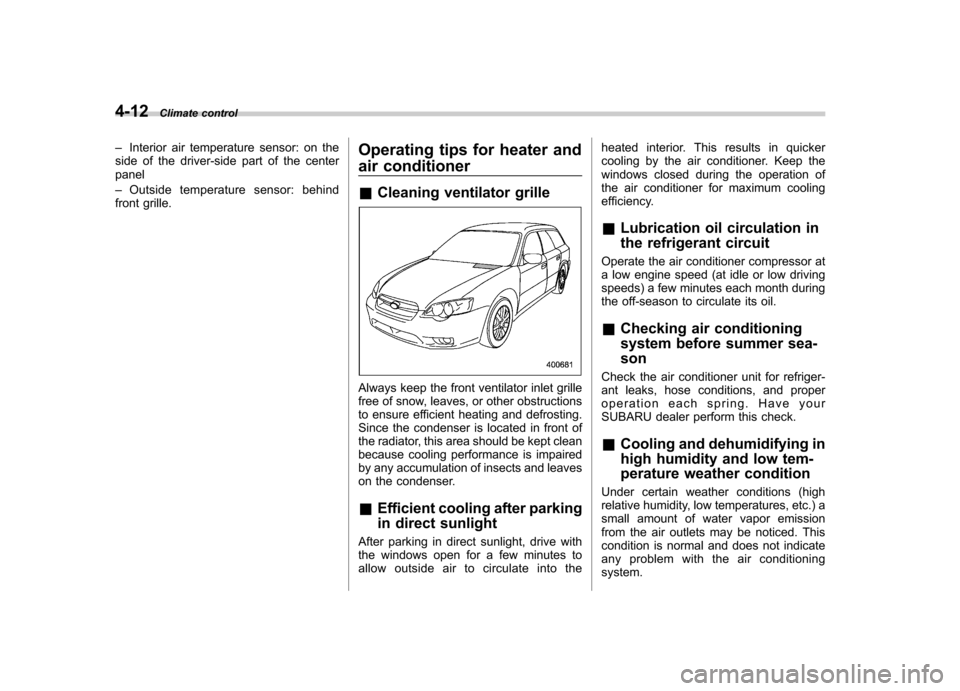
Cleaning ventilator grille
Always keep the front ventilator inlet grille
free of snow, leaves, or other obstructions
to ensure efficient heating and defrosting.
Since the condenser is located in front of
the radiator, this area should be kept clean
because cooling performance is impaired
by any accumulation of insects and leaves
on the condenser. &Efficient cooling after parking
in direct sunlight
After parking in direct sunlight, drive with
the windows open for a few minutes to
allow outside air to circulate into the heated interior. This results in quicker
cooling by the air conditioner. Keep the
windows closed during the operation of
the air conditioner for maximum cooling
efficiency. &
Lubrication oil circulation in
the refrigerant circuit
Operate the air conditioner compressor at
a low engine speed (at idle or low driving
speeds) a few minutes each month during
the off-season to circulate its oil. & Checking air conditioning
system before summer sea-son
Check the air conditioner unit for refriger-
ant leaks, hose conditions, and proper
operation each spring. Have your
SUBARU dealer perform this check. & Cooling and dehumidifying in
high humidity and low tem-
perature weather condition
Under certain weather conditions (high
relative humidity, low temperatures, etc.) a
small amount of water vapor emission
from the air outlets may be noticed. This
condition is normal and does not indicate
any problem with the air conditioningsystem.
Page 224 of 442

Outlet in cargo area
Accessory power outlets are provided
beside the front ashtray, in the center
console and in the cargo area. Electrical
power (12V DC) from the battery is
available at any of the outlets when the
ignition switch is in either the “ACC ”or
“ ON ”position.
You can use an in-car electrical appliance
by connecting it to an outlet.
The maximum power rating of an appli-
ance that can be connected varies among
outlets as shown in the following. Do not
use an appliance which exceeds the
indicated wattage for each outlet.
Outlet beside front pocket: 80W or less
Outlets in center console and cargo area:
120W or less
When using appliances connected to two or more outlets simultaneously, the total
power consumed by them must not
exceed 120W.
CAUTION
. Do not attempt to use a cigarette
lighter in the accessory power outlet.
. Do not place any foreign objects,
especially metal ones such as
coins or aluminum foil, into the
accessory power outlet. That
could cause a short circuit. Al-
ways put the cap on the acces-
sory power outlet when it is not
in use.
. Use only electrical appliances
which are designed for 12V DC.
The maximum power rating of an
appliance that can be connected
varies among outlets as shown in
the following. Do not use an
appliance which exceeds the in-
dicated wattage for each outlet.
Outlet beside front pocket: 80W
or less
Outlets in center console and
cargo area: 120W or less
When using appliances con-
nected to two or more outlets simultaneously, the total power
consumed by them must not
exceed 120W. Overloading the
accessory power outlet can
cause a short circuit. Do not use
double adapters or more than
one electrical appliance.
. If the plug on your electric appli-
ance is either too loose or too
tight for the accessory power
outlet, this can result in a poor
contact or cause the plug to get
stuck. Only use plugs that fit
properly.
. Use of an electric appliance in the
accessory power outlet for a long
period of time while the engine is
not running can cause batterydischarge.
. Before driving your vehicle, make
sure that the plug and the cord
on your electrical appliance will
not interfere with your shifting
gears and operating the accel-
erator and brake pedals. If they
do, do not use the electrical
appliance while driving. Interior equipment
6-9
– CONTINUED –