steering wheel SUBARU OUTBACK 2010 5.G User Guide
[x] Cancel search | Manufacturer: SUBARU, Model Year: 2010, Model line: OUTBACK, Model: SUBARU OUTBACK 2010 5.GPages: 448, PDF Size: 7.36 MB
Page 120 of 448

Instruments and controlsLight control switch ........................................... 3-27
Headlights. ......................................................... 3-27
High/low beam change (dimmer) ......................... 3-28
Headlight flasher ................................................ 3-28
Daytime running light system ............................. 3-29
Turn signal lever ................................................ 3-29
Illumination brightness control ......................... 3-30
Front fog light switch (if equipped) .................. 3-30Wiper and washer
.............................................. 3-31
Windshield wiper and washer switches .............. 3-32
Rear window wiper and washer switch (Outback) ........................................................ 3-34
Defogger and deicer .......................................... 3-34
Mirrors ................................................................ 3-36
Inside mirror ...................................................... 3-36
Auto-dimming mirror/compass (if equipped) ....... 3-36
Outside mirrors ................................................. 3-38
Tilt/telescopic steering wheel ........................... 3-38
Horn .................................................................... 3-39
Page 121 of 448
Ignition switch
WARNING
. Never turn the ignition switch to
“ LOCK ”while the vehicle is
being driven or towed because
that will lock the steering wheel,
preventing steering control. And
when the engine is turned off, it
takes a much greater effort than
usual to steer.
. Before leaving the vehicle, al-
ways remove the key from the
ignition switch for safety and
never allow an unattended child
to remain in the vehicle. Failure
to follow this procedure could
result in injury to a child or
others. Children could operate
the power windows, the sunroof
or other controls or even make
the vehicle move.
CAUTION
Do not attach a large key holder or
key case to either key. If it banged
against your knees or hands while
you are driving, it could turn the
ignition switch from the “ON ”posi- tion to the
“Acc ”or “LOCK ”posi-
tion, thereby stopping the engine.
Also, if the key is attached to a
keyholder or to a large bunch of
other keys, centrifugal force may act
on it as the vehicle moves, resulting
in unwanted turning of the ignitionswitch.
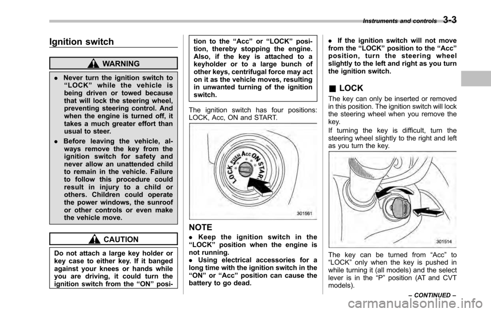
The ignition switch has four positions:
LOCK, Acc, ON and START.
NOTE . Keep the ignition switch in the
“ LOCK ”position when the engine is
not running. . Using electrical accessories for a
long time with the ignition switch in the“ ON ”or “Acc ”position can cause the
battery to go dead. .
If the ignition switch will not move
from the “LOCK ”position to the “Acc ”
position, turn the steering wheel
slightly to the left and right as you turn
the ignition switch.
& LOCK
The key can only be inserted or removed
in this position. The ignition switch will lock
the steering wheel when you remove the
key.
If turning the key is difficult, turn the
steering wheel slightly to the right and left
as you turn the key.
The key can be turned from “Acc ”to
“ LOCK ”only when the key is pushed in
while turning it (all models) and the select
lever is in the “P ” position (AT and CVT
models). Instruments and controls
3-3
– CONTINUED –
Page 156 of 448
3-38Instruments and controls
&Outside mirrors
! Convex mirror (passenger side)
WARNING
Objects look smaller in a convex
mirror and farther away than when
viewed in a flat mirror. Do not use
the convex mirror to judge the
distance of vehicles behind you
when changing lanes. Use the inside
mirror (or glance backwards) to
determine the actual size and dis-
tance of objects that you view in
convex mirror. !
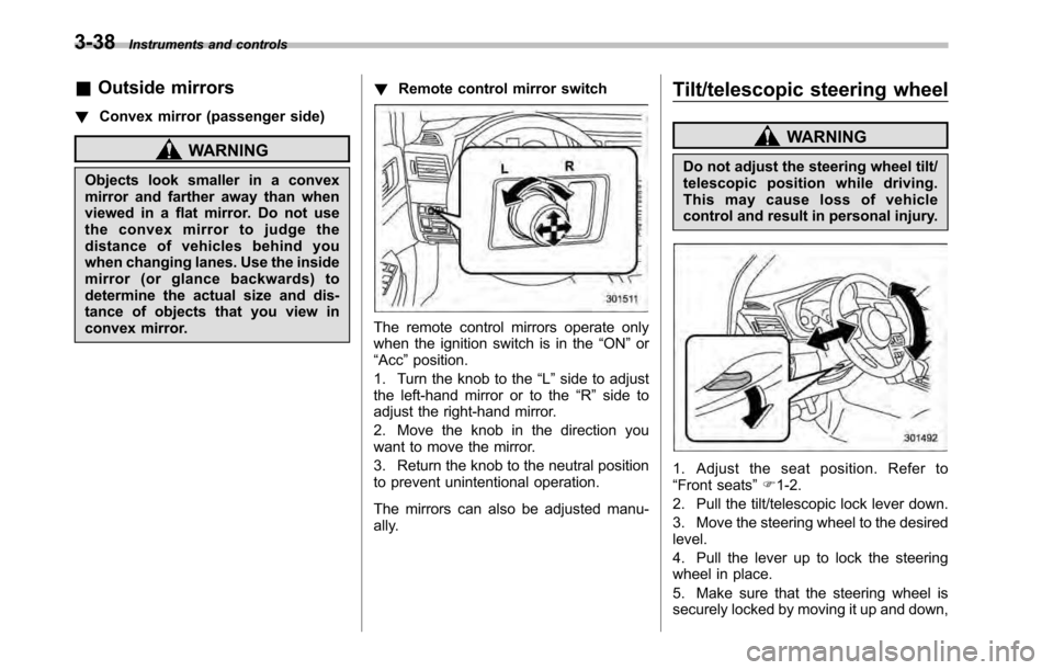
Remote control mirror switch
The remote control mirrors operate only
when the ignition switch is in the “ON ”or
“ Acc ”position.
1. Turn the knob to the “L ” side to adjust
the left-hand mirror or to the “R ” side to
adjust the right-hand mirror.
2. Move the knob in the direction you
want to move the mirror.
3. Return the knob to the neutral position
to prevent unintentional operation.
The mirrors can also be adjusted manu-
ally. Tilt/telescopic steering wheel
WARNING
Do not adjust the steering wheel tilt/
telescopic position while driving.
This may cause loss of vehicle
control and result in personal injury.
1. Adjust the seat position. Refer to “ Front seats ”F 1-2.
2. Pull the tilt/telescopic lock lever down.
3. Move the steering wheel to the desired level.
4. Pull the lever up to lock the steering
wheel in place.
5. Make sure that the steering wheel is
securely locked by moving it up and down,
Page 207 of 448
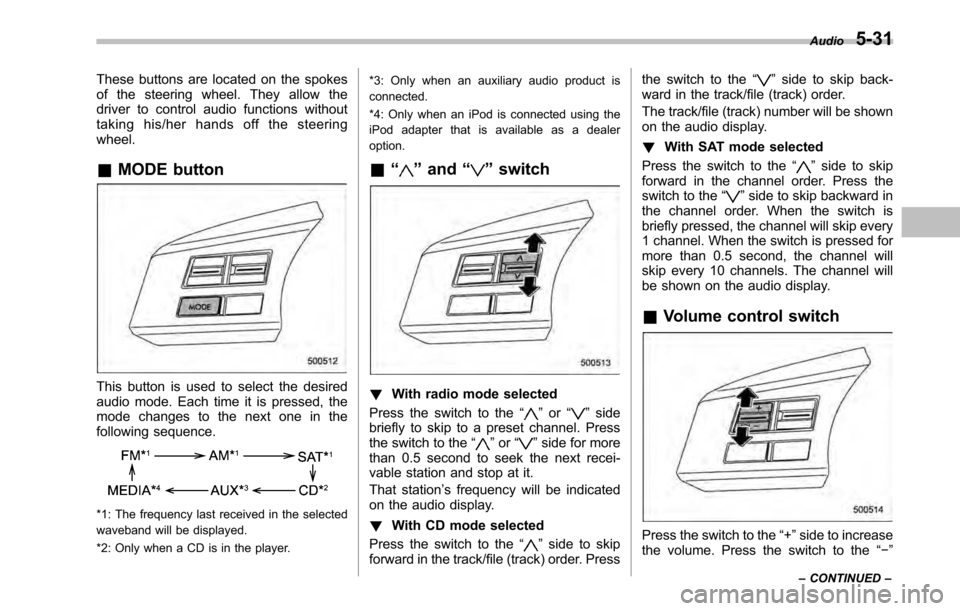
These buttons are located on the spokes
of the steering wheel. They allow the
driver to control audio functions without
taking his/her hands off the steeringwheel. &MODE button
This button is used to select the desired
audio mode. Each time it is pressed, the
mode changes to the next one in the
following sequence.
*1: The frequency last received in the selected
waveband will be displayed.
*2: Only when a CD is in the player. *3: Only when an auxiliary audio product is
connected.
*4: Only when an iPod is connected using the
iPod adapter that is available as a dealeroption.
& “
”and “”switch
! With radio mode selected
Press the switch to the “
”or “”side
briefly to skip to a preset channel. Press
the switch to the “
”or “”side for more
than 0.5 second to seek the next recei-
vable station and stop at it.
That station ’s frequency will be indicated
on the audio display. ! With CD mode selected
Press the switch to the “
”side to skip
forward in the track/file (track) order. Press the switch to the
“
”side to skip back-
ward in the track/file (track) order.
The track/file (track) number will be shown
on the audio display. ! With SAT mode selected
Press the switch to the “
”side to skip
forward in the channel order. Press the
switch to the “
”side to skip backward in
the channel order. When the switch is
briefly pressed, the channel will skip every
1 channel. When the switch is pressed for
more than 0.5 second, the channel will
skip every 10 channels. The channel will
be shown on the audio display.
& Volume control switch
Press the switch to the “+ ”side to increase
the volume. Press the switch to the “ ”
Audio
5-31
– CONTINUED –
Page 252 of 448
7-10Starting and operating
hard.
Stopping the engine
WARNING
Do not stop the engine when the
vehicle is moving. This will cause
loss of power to the power steering
and the brake booster, making steer-
ing and braking more difficult. It
could also result in accidental acti-
vation of the “LOCK ”position on the
ignition switch, causing the steering
wheel to lock.
The ignition switch should be turned off
only when the vehicle is stopped and the
engine is idling. Remote engine start system
(dealer option)
WARNING
. Do not remote start a vehicle in
an enclosed environment (e.g.
closed garage). Prolonged opera-
tion of a motor vehicle in an
enclosed environment can cause
a harmful build-up of Carbon
Monoxide. Carbon Monoxide is
harmful to your health. Exposure
to high levels of Carbon Monox-
ide can cause headaches, dizzi-
ness or in extreme cases uncon-
sciousness and/or death.
. Before performing any servicing
of the vehicle, temporarily place
the remote engine start system in
service mode to prevent the
system from unexpectedly start-
ing the engine.
Page 264 of 448
7-22Starting and operating
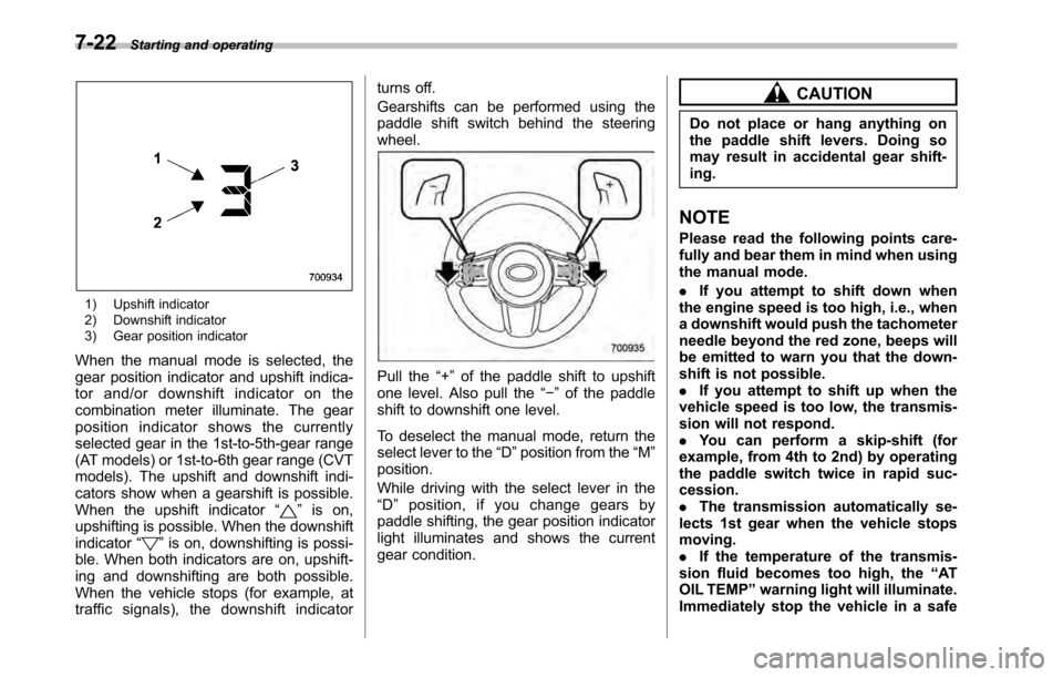
1) Upshift indicator
2) Downshift indicator
3) Gear position indicator
When the manual mode is selected, the
gear position indicator and upshift indica-
tor and/or downshift indicator on the
combination meter illuminate. The gear
position indicator shows the currently
selected gear in the 1st-to-5th-gear range
(AT models) or 1st-to-6th gear range (CVT
models). The upshift and downshift indi-
cators show when a gearshift is possible.
When the upshift indicator “
”is on,
upshifting is possible. When the downshift indicator “
”is on, downshifting is possi-
ble. When both indicators are on, upshift-
ing and downshifting are both possible.
When the vehicle stops (for example, at
traffic signals), the downshift indicator turns off.
Gearshifts can be performed using the
paddle shift switch behind the steeringwheel.
Pull the
“+ ” of the paddle shift to upshift
one level. Also pull the “ ” of the paddle
shift to downshift one level.
To deselect the manual mode, return the
select lever to the “D ”position from the “M ”
position.
While driving with the select lever in the “ D ” position, if you change gears by
paddle shifting, the gear position indicator
light illuminates and shows the current
gear condition.
CAUTION
Do not place or hang anything on
the paddle shift levers. Doing so
may result in accidental gear shift-ing.
NOTE
Please read the following points care-
fully and bear them in mind when using
the manual mode. . If you attempt to shift down when
the engine speed is too high, i.e., when
a downshift would push the tachometer
needle beyond the red zone, beeps will
be emitted to warn you that the down-
shift is not possible.. If you attempt to shift up when the
vehicle speed is too low, the transmis-
sion will not respond.. You can perform a skip-shift (for
example, from 4th to 2nd) by operating
the paddle switch twice in rapid suc-cession.. The transmission automatically se-
lects 1st gear when the vehicle stopsmoving.. If the temperature of the transmis-
sion fluid becomes too high, the “AT
OIL TEMP ”warning light will illuminate.
Immediately stop the vehicle in a safe
Page 265 of 448

place and let the engine idle until the
warning light turns off. &Driving tips
. On a road surface where there is a risk
of wheelspin (for example, a snow- or
gravel-covered road), you can pull away
from a standstill safely and easily by first
selecting the 2nd gear of the manualmode. . Always apply the foot or parking brake
when the vehicle is stopped in the “D ”or
“ R ”position.
. Always apply the parking brake when
parking your vehicle. Do not hold the
vehicle with only the transmission. . Do not keep the vehicle in a stationary
position on an uphill grade by using the “ D ”position. Use the brake instead.
. The engine may, on rare occasions,
knock when the vehicle rapidly acceler-
ates or rapidly pulls away from a standstill.
This phenomenon does not indicate afault. . A slight reduction in output torque may
occur in the models with a 2.5 L turbo or
3.6 L engine before the engine warms up. Power steering
CAUTION
Do not hold the steering wheel at the
fully locked position left or right for
more than 5 seconds. This may
damage the power steering pump.
The power steering system operates only
when the engine is running.
If you lose power steering assist because
the engine stops or the system fails to
function, you can steer but it will take
much more effort.
NOTE
Right after the engine has been started
and before it has warmed up, you may
hear a noise coming from areas adja-
cent to the power steering pump which
is located at the right-front area of the
engine compartment. This noise is
normal. It does not indicate power
steering system trouble. Braking &
Braking tips
WARNING
Never rest your foot on the brake
pedal while driving. This can cause
dangerous overheating of the
brakes and needless wear on the
brake pads and linings.
! When the brakes get wet
When driving in rain or after washing the
vehicle, the brakes may get wet. As a
result, brake stopping distance will be
longer. To dry the brakes, drive the vehicle
at a safe speed while lightly depressing
the brake pedal to heat up the brakes. ! Use of engine braking
Remember to make use of engine braking
in addition to foot braking. When descend-
ing a grade, if only the foot brake is used,
the brakes may start working improperly
because of brake fluid overheating,
caused by overheated brake pads. To
help prevent this, shift into a lower gear to
get stronger engine braking. ! Braking when a tire is punctured
Do not depress the brake pedal suddenly
when a tire is punctured. This could cause Starting and operating
7-23
– CONTINUED –
Page 267 of 448
ABS (Anti-lock Brake Sys- tem)
WARNING
Always use the utmost care in driving –overconfidence because
youaredrivingwithanABS
equipped vehicle could easily lead
to a serious accident.
CAUTION
. The ABS system does not always
decrease stopping distance. You
should always maintain a safe
following distance from othervehicles.
. When driving on badly surfaced
roads, gravel roads, icy road, or
over deep newly fallen snow,
stopping distances may be long-
er for a vehicle with the ABS
system than one without. When
driving under these conditions,
therefore, reduce your speed and
leave ample distance from othervehicles.
. When you feel the ABS system
operating, you should maintain constant brake pedal pressure.
Do not pump the brake pedal
since doing so may defeat the
operation of the ABS system.
The ABS system prevents the lock-up of
wheels which may occur during sudden
braking or braking on slippery road sur-
faces. This helps prevent the loss of
steering control and directional stability
caused by wheel lock-up.
When the ABS system is operating, you
may hear a chattering noise or feel a slight
vibration in the brake pedal. This is normal
when the ABS operates.
The ABS system will not operate when the
vehicle speed is below approximately 6
mph (10 km/h).
& ABS system self-check
You may feel a slight shock in the brake
pedal and hear the operating sound of
ABS from the engine compartment just
after the vehicle is started. This is caused
by an automatic functional test of the ABS
system being carried out and does not
indicate any abnormal condition. &
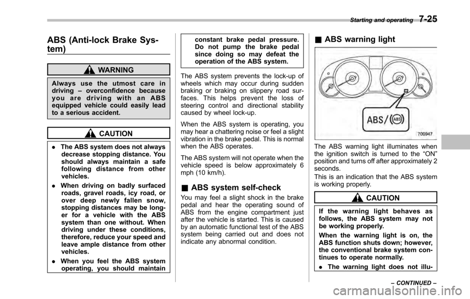
ABS warning light
The ABS warning light illuminates when
the ignition switch is turned to the “ON ”
position and turns off after approximately 2seconds.
This is an indication that the ABS system
is working properly.
CAUTION
If the warning light behaves as
follows, the ABS system may not
be working properly.
When the warning light is on, the
ABS function shuts down; however,
the conventional brake system con-
tinues to operate normally. . The warning light does not illu- Starting and operating
7-25
– CONTINUED –
Page 270 of 448
7-28Starting and operating
Vehicle Dynamics Control system
WARNING
Always use the utmost care in driving –overconfidence because
you are driving with a Vehicle Dy-
namics Control system equipped
vehicle could easily lead to a ser-
ious accident.
CAUTION
. Even if your vehicle is equipped
with Vehicle Dynamics Control
system, winter tires should be
used when driving on snow-cov-
ered or icy roads; in addition,
vehicle speed should be reduced
considerably. Simply having a
Vehicle Dynamics Control sys-
tem does not guarantee that the
vehicle will be able to avoid
accidents in any situation.
. Activation of the Vehicle Dy-
namics Control system is an
indication that the road being
travelled on has a slippery sur-
face; since having Vehicle Dy-
namics Control is no guarantee that full vehicle control will be
maintained at all times and under
all conditions, its activation
should be seen as a sign that
the speed of the vehicle should
be reduced considerably.
. Whenever suspension compo-
nents, steering components, or
an axle are removed from a
vehicle equipped with Vehicle
Dynamics Control, have an
authorized SUBARU dealer per-
form an inspection of that sys-tem.
. The following precautions should
be observed in order to ensure
that the Vehicle Dynamics Con-
trol system is operating properly. – All four wheels should be
fitted with tires of the same
size, type, and brand. Further-
more, the amount of wear
should be the same for all
four tires.
– Keep the tire pressure at the
proper level as shown on the
vehicle placard attached to
the driver ’s side door pillar.
– Use only the specified tem-
porary spare tire to replace a
flat tire. With a temporary spare tire, the effectiveness of
the Vehicle Dynamics Control
system is reduced and this
should be taken into account
when driving the vehicle in
such a condition.
In the event of wheelspin and/or skidding
on a slippery road surface and/or during
cornering and/or an evasive maneuver,
the Vehicle Dynamics Control system
adjusts the engine ’s output and the
wheels ’respective braking forces to help
maintain traction and directional control. . Traction Control Function
The traction control function is designed to
prevent spinning of the driving wheels on
slippery road surfaces, thereby helping to
maintain traction and directional control.
Activation of this function is indicated by
flashing of the Vehicle Dynamics Control
operation indicator light. . Skid Suppression Function
The skid suppression function is designed
to help maintain directional stability by
suppressing the wheels ’tendency to slide
sideways during steering operations. Acti-
vation of this function is indicated by
flashing of the Vehicle Dynamics Control
operation indicator light.
Page 271 of 448

NOTE .Slight twitching of the brake pedal
may be felt when the Vehicle Dynamics
Control system operates; a small de-
gree of vehicle or steering wheel shak-
ing may also be noticed in this situa-
tion. These are normal characteristics
of Vehicle Dynamics Control operation
and are no cause for alarm.. When driving off immediately after
starting the engine, a short-lived opera-
tion noise may be noticed coming from
the engine compartment. This noise is
generated as a result of a check being
performed on the Vehicle Dynamics
Control system and is normal.. Depending on the timing of activa-
tion of the brakes, the brake pedal may
seem to jolt when you drive off after
starting the engine. This is a conse-
quence of the Vehicle Dynamics Con-
trol operational check and is normal.. In the circumstances shown in the
following list, the vehicle may be more
unstable than it feels to the driver. The
Vehicle Dynamics Control System may
therefore operate. Such operation does
not indicate a system fault.
–on gravel-covered or rutted
roads – on unfinished roads
– when the vehicle is towing a trailer–
when the vehicle is fitted with
snow tires or winter tires
. Activation of the Vehicle Dynamics
Control system will cause operation of
the steering wheel to feel slightly
different compared to that for normalconditions. . Even if the vehicle is equipped with
a Vehicle Dynamics Control system, it
is important that winter tires be used
when driving on snow-covered or icy
roads. (All four wheels should be fitted
with tires of the same size and brand.) . It is always important to reduce
speed when appro aching a corner,
even if the vehicle is equipped with
Vehicle Dynamics Control. . All four wheels should be fitted with
tires of the same size, type, and brand;
furthermore, the amount of wear
should be the same for all four tires. If
these precautions are not observed
and non-matching tires are used, it is
quite possible that the Vehicle Dy-
namics Control system will be unable
to operate correctly as intended. . Always turn off the engine before
replacing a tire as failure to do so may
render the Vehicle Dynamics Control
system unable to operate correctly. &
Vehicle Dynamics Control
system monitor
! Vehicle Dynamics Control warning
light/Vehicle Dynamics Control op-
eration indicator light
The light illuminates when the ignition
switch is turned to the “ON ”position and
turns off several seconds after the engine
has started. This lighting pattern indicates
that the Vehicle Dynamics Control system
is operating normally. ! Vehicle Dynamics Control warning light
CAUTION
Because the Vehicle Dynamics Con-
trol system controls each brake Starting and operating
7-29
– CONTINUED –