ABS SUBARU OUTBACK 2012 5.G Owners Manual
[x] Cancel search | Manufacturer: SUBARU, Model Year: 2012, Model line: OUTBACK, Model: SUBARU OUTBACK 2012 5.GPages: 474, PDF Size: 17.45 MB
Page 5 of 474
2
Chapter 12: Specifications
This chapter informs you about the dimen-
sions and capacities of your SUBARU.
Chapter 13: Consumer information and
Reporting safety defects
This chapter informs you about Tire
information, Uniform tire quality grading
standards and Reporting safety defects.
Chapter 14: Index
This is an alphabetical listing of all that’sin
this manual. You can use it to quickly find
something you want to read. & Safety warnings
You will find a number of WARNINGs,
CAUTIONs and NOTEs in this manual.
These safety warnings alert you to poten-
tial hazards that could result in injury to
you or others.
Please read these safety warnings as well
as all other portions of this manual care-
fully in order to gain a better understand-
ing of how to use your SUBARU vehicle
safely.
WARNING
A WARNING indicates a situation in
which serious injury or death could
result if the warning is ignored.
CAUTION
A CAUTION indicates a situation in
which injury or damage to your
vehicle, or both, could result if the
caution is ignored.
NOTE
A NOTE gives information or sugges-
tions how to make better use of yourvehicle. & Safety symbol
You will find a circle with a slash through it
in this manual. This symbol means “Do
not ”, “Do not do this ”,or “Do not let this
happen ”, depending upon the context. &
Abbreviation list
You will find several abbreviations in this
manual. The meanings of the abbrevia-
tions are shown in the following list.
Abbreviation Meaning
A/C Air conditioner A/ELR Automatic/Emergency locking retractor
ABS Anti-lock brake system
AKI Anti knock index
ALR Automatic locking retractor
AT Automatic transmission
ATF Automatic transmission fluid
AWD All-wheel drive CVT Continuously variable trans- mission
DRL Daytime running light EBD Electronic brake force distri- bution
ELR Emergency locking retractor
FWD Front-wheel drive
GAW Gross axle weight
GAWR Gross axle weight rating
GPS Global positioning system
GVW Gross vehicle weight
GVWR Gross vehicle weight rating
Page 22 of 474

&Warning and indicator lights
Mark Name Page
Seatbelt warning light 3-9
Front passenger ’s
seatbelt warning light 3-9
SRS airbag system
warning light3-11
CHECK ENGINE warn-
ing light/Malfunction in-
dicator light3-12
Coolant temperature
low indicator light/Cool-
ant temperature high
warning light3-13
Charge warning light 3-14
Oil pressure warning light
3-14
Engine oil level warning light3-14
AT OIL TEMP warning
light (AT and CVT mod- els)3-14
/ABS warning light 3-16 Mark Name Page
/Brake system warning light
3-17
Hill Holder indicator light3-19
Door open indicator light
3-19
Low fuel warning light 3-19
All-Wheel Drive warn-
ing light (AT and CVT models)3-20
Vehicle Dynamics Con-
trol warning light/Vehi-
cle Dynamics Control
operation indicator light3-20
Vehicle Dynamics Con-
trol OFF indicator light
3-21
Security indicator light 3-21
Turn signal indicator lights
3-22
High beam indicator light3-22
Front fog light indicator
light (if equipped)3-23Mark Name Page
Cruise control indicator light
3-23
Cruise control set indi-
cator light3-23
Headlight indicator light 3-23
Low tire pressure
warning light
(U.S. spec. models)3-15
/Front passenger
’s fron-
tal airbag ON indicator light 3-11
/Front passenger
’s fron-
tal airbag OFF indicator light 3-11
Shift-up indicator 3-22
Windshield washer fluid
warning light
3-1919
Page 120 of 474
Ignition switch..................................................... 3-3
LOCK .................................................................. 3-3
Acc..................................................................... 3-4
ON...................................................................... 3-4
START ................................................................ 3-4
Key reminder chime ............................................ 3-4
Ignition switch light ............................................. 3-4
Hazard warning flasher ....................................... 3-5
Meters and gauges. ............................................. 3-5
Combination meter illumination ........................... 3-5
Canceling the function for meter/gauge needle movement upon turning on the ignition switch ............................................................... 3-5
Speedometer ....................................................... 3-6
Odometer ............................................................ 3-6
Double trip meter ................................................ 3-6
Tachometer ......................................................... 3-7
Fuel gauge .......................................................... 3-7
ECO gauge ......................................................... 3-8
Warning and indicator lights .............................. 3-9
Seatbelt warning light and chime ......................... 3-9
SRS airbag system warning light ........................ 3-11
Front passenger ’s frontal airbag ON and OFF
indicators ......................................................... 3-11
CHECK ENGINE warning light/Malfunction indicator light ................................................... 3-12
Coolant temperature low indicator light/Coolant temperature high warning light ......................... 3-13
Charge warning light .......................................... 3-14
Oil pressure warning light .................................. 3-14
Engine low oil level warning light ....................... 3-14AT OIL TEMP warning light (AT and CVT
models) ........................................................... 3-14
Low tire pressure warning light (U.S. spec. models) ........................................................... 3-15
ABS warning light .............................................. 3-16
Brake system warning light ................................ 3-17
Hill Holder indicator light ................................... 3-19
Low fuel warning light ....................................... 3-19
Door open indicator light ................................... 3-19
Windshield washer fluid warning light ................ 3-19
All-Wheel Drive warning light (AT and CVT models) ........................................................... 3-20
Vehicle Dynamics Control warning light/Vehicle Dynamics Control operation indicator light .. ..... 3-20
Vehicle Dynamics Control OFF indicator light ..... 3-21
Security indicator light ....................................... 3-21
Select lever/gear position indicator ..................... 3-22
Turn signal indicator lights ................................. 3-22
High beam indicator light ................................... 3-22
Cruise control indicator light .............................. 3-23
Cruise control set indicator light ........................ 3-23
Headlight indicator light ..................................... 3-23
Front fog light indicator light (if equipped) ..... ..... 3-23
Clock .................................................................. 3-23
Multi function display ........................................ 3-24
Outside temperature indicator .. .......................... 3-24
Average fuel consumption ................................. 3-25
Current fuel consumption .................................. 3-26
Driving range on remaining fuel ......................... 3-26
Light control switch ........................................... 3-27
Headlights ......................................................... 3-27
Instruments and controls
3
Page 128 of 474

Warning and indicator lights
Several of the warning and indicator lights
illuminate momentarily and then go out
when the ignition switch is initially turned
to the“ON ”position. This permits check-
ing the operation of the bulbs.
Apply the parking brake and turn the
ignition switch to the “ON ”position. For
the system check, the following lights
illuminate and turn off after several sec-
onds or after the engine has started:
: Seatbelt warning light (The seatbelt warning light turns off
only when the driver fastens the seatbelt.)
: Front passenger ’s seatbelt warning
light
(The seatbelt warning light turns off
only when the front seat passenger
fastens the seatbelt.)
: SRS airbag system warning light
ON /
: Front passenger ’s frontal airbag
ON indicator light
/: Front passenger ’s frontal airbag
OFF indicator light
: CHECK ENGINE warning light/Mal- function indicator light
: Coolant temperature high warning light
: Charge warning light
: Oil pressure warning light
: Engine low oil level warning light
: Windshield washer fluid warning light
: AT OIL TEMP warning light(AT and CVT models)
/: ABS warning light
: Vehicle Dynamics Control warning light/Vehicle Dynamics Control opera-
tion indicator light
: Vehicle Dynamics Control OFF indica-
tor light
/: Brake system warning light
: Hill Holder indicator light
: All-Wheel Drive warning light (AT andCVT models)
: Low tire pressure warning light (U.S. spec. models)
: Low fuel warning light
: Door open indicator light
: Cruise control indicator light
: Cruise control set indicator light
: Select lever/gear position indicator
If any lights fail to illuminate, it indicates a
burned-out bulb or a malfunction of the
corresponding system.
Consult your authorized SUBARU dealer
for repair. & Seatbelt warning light
and chime
Your vehicle is equipped with a seatbelt
warning device at the driver ’s and front
passenger ’s seat, as required by current
safety standards.
With the ignition switch turned to the “ON ”
position, this device reminds the driver
and front passenger to fasten their seat-
belts by the warning lights in the locations
indicated in the following illustration and achime. Instruments and controls
3-9
– CONTINUED –
Page 135 of 474
3-16Instruments and controls
ally reducing speed. Then slowly
pull off the road to a safe place.
Otherwise an accident involving
serious vehicle damage and serious
personal injury could occur.
If this light still illuminates while
driving after adjusting the tire pres-
sure, a tire may have significant
damage and a fast leak that causes
the tire to lose air rapidly. If you have
a flat tire, replace it with a spare tire
as soon as possible.
When a spare tire is mounted or a
wheel rim is replaced without the
original pressure sensor/transmitter
being transferred, the Low tire pres-
sure warning light will illuminate
steadily after blinking for approxi-
mately one minute. This indicates
the TPMS is unable to monitor all
four road wheels. Contact your
SUBARU dealer as soon as possible
for tire and sensor replacement and/
or system resetting. If the light
illuminates steadily after blinking
for approximately one minute,
promptly contact a SUBARU dealer
to have the system inspected.CAUTION
The tire pressure monitoring system
is NOT a substitute for manually
checking tire pressure. The tire
pressure should be checked peri-
odically (at least monthly) using a
tire gauge. After any change to tire
pressure(s), the tire pressure mon-
itoring system will not re-check tire
inflation pressures until the vehicle
is first driven more than 20 mph (32
km/h). After adjusting the tire pres-
sures, increase the vehicle speed to
at least 20 mph (32 km/h) to start the
TPMS re-checking of the tire infla-
tion pressures. If the tire pressures
are now above the severe low
pressure threshold, the low tire
pressure warning light should turn
off a few minutes later. Therefore, be
sure to install the specified size for
the front and rear tires.
& ABS warning light
CAUTION
. If any of the following conditions
occur, we recommend that you
have the ABS system repaired at
the first available opportunity by your SUBARU dealer. –
The warning light does not
illuminate when the ignition
switch is turned to the “ON ”
position.
– The warning light illuminates
when the ignition switch is
turned to the “ON ”position,
but it does not turn off even
when the vehicle speed ex-
ceeds approximately 12 km/h
(8 mph).
– The warning light illuminates
during driving.
– The warning light flashes.
. When the warning light is on (and
brake system warning light is
off), the ABS function shuts
down; however, the conventional
brake system continues to oper-
ate normally.
. When the warning light is flash-
ing, the ABS system may be
malfunctioning. However, the
conventional brake system con-
tinues to operate normally.
The ABS warning light illuminates to-
gether with the brake system warning light
if the EBD system malfunctions. For
further details of the EBD system mal-
Page 136 of 474
function warning, refer to“Brake system
warning light ”F 3-17.
NOTE
If the warning light behavior is as
described in the following conditions,
the ABS system may be considered normal. . The warning light illuminates right
after the engine is started but turns off
immediately, remaining off.. The warning light remains illumi-
nated after the engine has been started,
but it turns off when the vehicle speed
reaches approximately 8 mph (12km/h).. The warning light illuminates during
driving, but it turns off immediately and
remains off.
When driving with an insufficient battery
voltage such as when the engine is jump
started, the ABS warning light may illumi-
nate. This is due to the low battery voltage
and does not indicate a malfunction.
When the battery becomes fully charged,
the light will turn off. &
Brake system
warning light
WARNING
. Driving with the brake system
warning light on is dangerous.
This indicates your brake system
may not be working properly. If
the light remains illuminated,
have the brakes inspected by a
SUBARU dealer immediately.
. If at all in doubt about whether
the brakes are operating prop-
erly, do not drive the vehicle.
Have your vehicle towed to the
nearest SUBARU dealer for re-
pair.
. If the brake system warning light
flashes, the electronic parking
brake system may be malfunc-
tioning. Immediately stop your
vehicle in a safe location, use
tire stops under the tires to
prevent the vehicle from moving
and contact your SUBARU deal-
er. For details, refer to “Electro-
nic parking brake ”F 7-31. NOTE .
When the ignition switch is turned to
the “LOCK ”position with the electronic
parking brake applied, the brake sys-
tem warning light remains illuminated
for approximately 30 seconds and then
turns off.. When the electronic parking brake
switch is pressed to apply the electro-
nic parking brake while the ignition
switch is in the “LOCK ”position, the
brake system warning light illuminates,
remains illuminated for approximately
30 seconds and then turns off.. Even if the brake system warning
light flashes, if the warning light beha-
vior is as described in the following
examples, the electronic parking brake
system is not malfunctioning.
–The warning light turns off when
the electronic parking brake is ap-
plied or released. – The warning light turns off when
the ignition switch is turned to the “ ON ”position again.
. The brake system warning light may
flash immediately after the engine is
started. However, it is not malfunction-
ing if the warning light turns off after
the electronic parking brake is re-leased. . The brake system warning light may Instruments and controls
3-17
– CONTINUED –
Page 137 of 474
3-18Instruments and controls
flash after the electronic parking brake
is frequently applied and released.
However, the electronic parking brake
system is not malfunctioning if the light
turns off for a short period of time.
This light has the following functions: ! Parking brake warning
The light illuminates with the parking
brake applied while the ignition switch is
in the “ON ”position. It turns off when the
parking brake is released. ! Brake fluid level warning
This light illuminates when the brake fluid
level has dropped to near the “MIN ”level
of the brake fluid reservoir with the ignition
switch in the “ON ”position and with the
parking brake released.
If the brake system warning light should
illuminate while driving (with the parking
brake released and with the ignition switch
positioned in “ON ”), it could be an indica-
tion of leaking of brake fluid or worn brake
pads. If this occurs, immediately stop the
vehicle at the nearest safe place and
check the brake fluid level. If the fluid level
is below the “MIN ”mark in the reservoir,
do not drive the vehicle. Have the vehicle
towed to the nearest SUBARU dealer for
repair. !
Electronic Brake Force Distribution
(EBD) system warning
The brake system warning light also
illuminates if a malfunction occurs in the
EBD system. In that event, it illuminates
together with the ABS warning light.
The EBD system may be malfunctioning if
the brake system warning light and ABS
warning light illuminate simultaneously
during driving.
Even if the EBD system fails, the conven-
tional braking system will still function.
However, the rear wheels will be more
prone to locking when the brakes are
applied harder than usual and the vehi-cle ’s motion may therefore become some-
what harder to control.
If the brake system warning light and ABS
warning light illuminate simultaneously,
take the following steps:
1. Stop the vehicle in the nearest safe,
flat place.
2. Shut down the engine, then restart it.
3. Release the parking brake. If both
warning lights turn off, the EBD system
may be malfunctioning.
Drive carefully to the nearest SUBARU
dealer and have the system inspected.
4. If both warning lights illuminate again
and remain illuminated after the engine
has been restarted, shut down the engine again, apply the parking brake, and check
the brake fluid level. Refer to
“Brake fluid ”
F 11-25.
5. If the brake fluid level is not below the“ MIN ”mark, the EBD system may be
malfunctioning. Drive carefully to the
nearest SUBARU dealer and have the
system inspected.
6. If the brake fluid level is below the “ MIN ”mark, DO NOT drive the vehicle.
Instead, have the vehicle towed to the
nearest SUBARU dealer for repair. ! Electronic parking brake system warning
The brake system warning light flashes
when the electronic parking brake system
is malfunctioning. If the warning light
flashes, promptly park in a safe location
as soon as possible and contact your
SUBARU dealer.
The brake system warning light remains
illuminated when the parking brake cannot
be released even if the parking brake
switch is pulled. For details, refer to“ Electronic parking brake ”F 7-31.
! Parking brake apply inhibit warning
The brake system warning light flashes for
10 seconds and a chirp sound will be
heard if the parking brake switch is
operated when the parking brake cannot
Page 139 of 474
3-20Instruments and controls
&All-Wheel Drive
warning light (AT and
CVT models)
WARNING
Continued driving with the AWD
warning light flashing can lead to
powertrain damage. If the AWD
warning light flashes, promptly park
in a safe place then check whether
all four tires are the same diameter
and whether any of the tires has a
puncture or has lost air pressure for
some other reason.
NOTE
If the temporary spare tire is used, the
AWD warning light may flash. Use of
the temporary spare tire should there-
fore be restricted to the minimum time
necessary. Replace the temporary
spare tire with a conventional tire as
soon as possible.
This light flashes if the vehicle is driven
with tires of different diameters fitted on its
wheels or with the air pressure exces-
sively low in any of its tires. &
Vehicle Dynamics
Control warning light/
Vehicle Dynamics Con-
trol operation indicatorlight
!Vehicle Dynamics Control warning light
CAUTION
The Vehicle Dynamics Control sys-
tem provides its ABS control
through the electrical circuit of the
ABS system. Accordingly, if the ABS
is inoperative, the Vehicle Dynamics
Control system becomes unable to
provide ABS control. As a result, the
Vehicle Dynamics Control system
becomes inoperative, causing the
warning light to illuminate. Although
both the Vehicle Dynamics Control
and ABS systems are inoperative in
this case, the ordinary functions of
the brake system are still available.
You will be safe while driving in this
condition, but drive carefully and
have your vehicle checked at a
SUBARU dealer as soon as possi-ble. NOTE .
If the electrical circuit of the Vehicle
Dynamics Control system itself mal-
functions, the warning light only illumi-
nates. At this time, the ABS (Anti-lock
Brake System) remains fully opera-tional.. The warning light illuminates when
the electronic control system of the
ABS/Vehicle Dynamics Control systemmalfunctions.
The Vehicle Dynamics Control system is
probably inoperative under any of the
following conditions. Have your vehicle
checked at a SUBARU dealer immedi-
ately. . The warning light does not illuminate
when the ignition switch is turned to the “ ON ”position.
. The warning light illuminates while the
vehicle is running. NOTE
If the warning light behavior is as
described in the following examples,
the Vehicle Dynamics Control system
may be considered normal. . The warning light illuminates right
after the engine is started but turns off
immediately and remains off.. The warning light illuminates after
the engine has started and turns off
Page 191 of 474
5-8Audio
Power and audio controls &Power switch and volume control
Type A audio
Type B audio
Type C audio
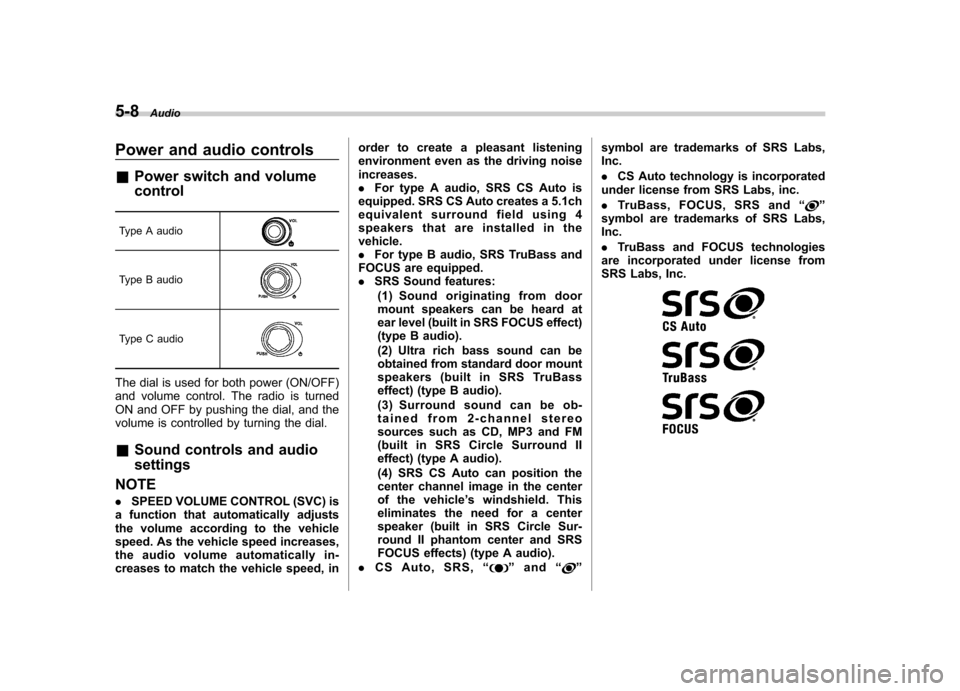
The dial is used for both power (ON/OFF)
and volume control. The radio is turned
ON and OFF by pushing the dial, and the
volume is controlled by turning the dial. & Sound controls and audio settings
NOTE . SPEED VOLUME CONTROL (SVC) is
a function that automatically adjusts
the volume according to the vehicle
speed. As the vehicle speed increases,
the audio volume automatically in-
creases to match the vehicle speed, in order to create a pleasant listening
environment even as the driving noiseincreases..
For type A audio, SRS CS Auto is
equipped. SRS CS Auto creates a 5.1ch
equivalent surround field using 4
speakers that are installed in thevehicle.. For type B audio, SRS TruBass and
FOCUS are equipped.. SRS Sound features:
(1) Sound originating from door
mount speakers can be heard at
ear level (built in SRS FOCUS effect)
(type B audio).
(2) Ultra rich bass sound can be
obtained from standard door mount
speakers (built in SRS TruBass
effect) (type B audio).
(3) Surround sound can be ob-
tained from 2-channel stereo
sources such as CD, MP3 and FM
(built in SRS Circle Surround II
effect) (type A audio).
(4) SRS CS Auto can position the
center channel image in the center
of the vehicle ’s windshield. This
eliminates the need for a center
speaker (built in SRS Circle Sur-
round II phantom center and SRS
FOCUS effects) (type A audio).
. CS Auto, SRS, “
”and “”symbol are trademarks of SRS Labs, Inc. .
CS Auto technology is incorporated
under license from SRS Labs, inc.. TruBass, FOCUS, SRS and “
”
symbol are trademarks of SRS Labs, Inc. . TruBass and FOCUS technologies
are incorporated under license from
SRS Labs, Inc.
Page 235 of 474
5-52Audio
&Safety precautions
WARNING
. For safety reasons, avoid operat-
ing the cell phone while driving.
. Do not make a phone call while
driving. When you have an in-
coming call, stop the vehicle in a
safe location before taking the
incoming phone call. When you
have to absolutely take a phone
call, tell the caller “I’ ll call you
back ”. And then call the caller
back after stopping the vehicle in
a safe location.
. Part 15 FCC Rules
FCC Warning:
Any unauthorized changes of
modifications to this equipment
would void the user ’s authority to
operate this device.
CAUTION
. Do not leave the cell phone in the
vehicle. The temperature in the
vehicle may become extremely
high and cause a malfunction of
the cell phone. .
When using the cell phone, be
careful not to get it close to the
in-vehicle equipment. Getting it
too close to the in-vehicle equip-
ment may result in deterioration
in tone quality or a poor connect-
ing condition.
. In the frequency band used by
this equipment, along with indus-
trial, scientific and medical
equipment such as a microwave
oven, radio stations (a license is
required) to be used by the
production line in the factory to
identify movable bodies, specific
small power radio stations (a
license is not required) and ama-
teur radio stations (a license is
required) are being operated.
(These three types of radio sta-
tions are hereinafter referred toas “other radio stations ”.) Before
using this equipment, be sure to
check to see if “other radio
stations ”are being operated in
the vicinity. If there is detrimental
radio interference from this
equipment to “other radio sta-
tions ”, move the equipment to
another location as soon as
possible to avoid radio interfer-
ence. The frequency band used by this equipment is in the 2.4
GHz zone. The FH-SS modulation
is employed as a modulation
method. The expected inflicting
interference distance is less than
33 ft (10 m). This equipment uses
a full band and can avoid a band
used by a movable body identifi-
cation device.
& Using the Hands-free system
! Turning on/off the Hands-free mode
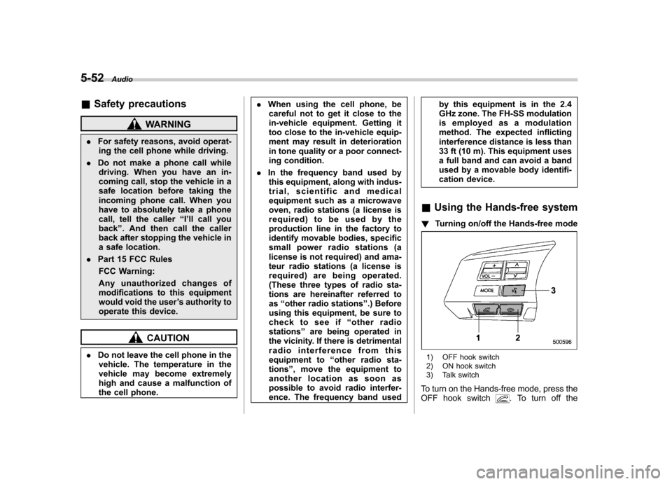
1) OFF hook switch
2) ON hook switch
3) Talk switch
To turn on the Hands-free mode, press the
OFF hook switch
. To turn off the