blue light SUBARU OUTBACK 2012 5.G Owners Manual
[x] Cancel search | Manufacturer: SUBARU, Model Year: 2012, Model line: OUTBACK, Model: SUBARU OUTBACK 2012 5.GPages: 474, PDF Size: 17.45 MB
Page 132 of 474

&Coolant temperature
low indicator light/Cool-
ant temperature high
warning light
CAUTION
. After turning the ignition switch
to the “ON ”position, if this
indicator light/warning light be-
haves under any of the following
conditions, the electrical system
may be malfunctioning. Contact
your SUBARU dealer immedi-
ately for an inspection. – It remains blinking in RED.
– It remains illuminated in RED
for more than 2 seconds.
– It remains blinking in RED and
BLUE alternately.
. While driving, if this indicator
light/warning light behaves under
any of the following conditions,
take the specified appropriate
measure listed below. – Blinking in RED:
Decelerate the vehicle. After
the blinking RED light turns
off, you can drive the vehicle
normally.
– Illuminated in RED: Safely stop the vehicle as
soon as possible, and refer
to the emergency steps for the
case of engine overheating.
After that, have the system
checked by your nearest
SUBARU dealer. Refer to
“En-
gine overheating ”F 9-13.
– Blinking in RED and BLUE
alternately:
The electrical system may be
malfunctioning. Contact your
SUBARU dealer for an inspec-tion.
This coolant temperature low indicator
light/coolant temperature high warning
light has the following three functions. . Illumination in BLUEindicates insuffi-
cient warming up of the engine. Blinking in REDindicates that the
engine is close to overheating. Illumination in REDindicates overheat-
ing condition of the engine
For the system check, this indicator light/
warning light illuminates in REDfor
approximately 2 seconds when the igni-
tion switch is turned to the “ON ”position.
After that, this indicator light/warning light
changes to BLUEand maintains illumina-
tion in BLUE. This BLUE illuminated light turns off when the engine is warmed up
sufficiently.
If the engine coolant temperature in-
creases over the specified range, the
indicator light/warning light blinks in RED
. At this time, decelerate the vehicle.
After the blinking REDlight turns off, you
can drive the vehicle normally. However, if
the indicator light/warning light often blinksin RED , the electrical system may be
malfunctioning. Contact your SUBARU
dealer for an inspection.
If the engine coolant temperature in-
creases further, the indicator light/warning
light illuminates in REDcontinuously. At
this time, the engine may be overheating.
Safely stop the vehicle as soon as
possible, and refer to the emergency
steps for the case of engine overheating.
Refer to “Engine overheating ”F9-13.
After that, have the system checked by
your nearest SUBARU dealer.
NOTE
If the engine is restarted after a certain
driving condition, this indicator light/
warning light may illuminate in RED.
However, this is not a malfunction if the
indicator light/warning light turns off
after a short time. Instruments and controls
3-13
– CONTINUED –
Page 178 of 474

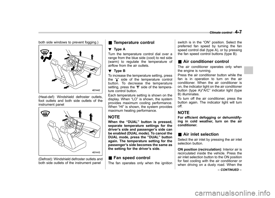
both side windows to prevent fogging.)
(Heat-def): Windshield defroster outlets,
foot outlets and both side outlets of the
instrument panel
(Defrost): Windshield defroster outlets and
both side outlets of the instrument panel&
Temperature control
! Type A
Turn the temperature control dial over a
range from the blue side (cool) to red side
(warm) to regulate the temperature of
airflow from the air outlets. ! Type B
To increase the temperature setting, press the “
”side of the temperature control
button. To decrease the temperature
setting, press the “
”side of the tempera-
ture control button.
Each temperature setting is shown on the
display. When “LO ”is shown, the system
provides maximum cooling performance.When “HI ”is shown, the system provides
maximum heating performance.
NOTE
When the “DUAL ”button is pressed,
separate temperature settings for the driver ’s side and passenger ’s side can
be enabled (DUAL mode). To cancel the
DUAL mode, press the “DUAL ”button
again. The temperature setting for thepassenger ’s side becomes the same as
the setting for the driver ’s side.
& Fan speed control
The fan operates only when the ignition switch is in the
“ON ”position. Select the
preferred fan speed by turning the fan
speed control dial (type A), or by pressing
the fan speed control buttons (type B).
& Air conditioner control
The air conditioner operates only when
the engine is running.
Press the air conditioner button while the
fan is in operation to turn on the air
conditioner. When the air conditioner is
on, the indicator light on the air conditioner
button (type A)/ “A/C ”indicator light (type
B) illuminates.
To turn off the air conditioner, press the
button again. The indicator light will turnoff. NOTE
For efficient defogging or dehumidify-
ing in cold weather, turn on the air
conditioner. & Air inlet selection
Select the air inlet by pressing the air inlet
selection button.
ON position (recirculation) : Interior air is
recirculated inside the vehicle. Press the
air inlet selection button to the ON position
for fast cooling with the air conditioner or
when driving on a dusty road. When the Climate control
4-7
– CONTINUED –
Page 386 of 474

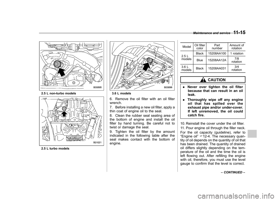
2.5 L non-turbo models
2.5 L turbo models
3.6 L models
6. Remove the oil filter with an oil filter wrench.
7. Before installing a new oil filter, apply a
thin coat of engine oil to the seal.
8. Clean the rubber seal seating area of
the bottom of engine and install the oil
filter by hand turning. Be careful not to
twist or damage the seal.
9. Tighten the oil filter by the amount
indicated in the following table after the
seal makes contact with the bottom of engine. Model
Oil filter
color Part
number Amount of
rotation
2.5 L models Black 15208AA100 1 rotation
Blue 15208AA12A 7/8
rotation
3.6 Lmodels Black 15208AA031 3/4
rotation
CAUTION
. Never over tighten the oil filter
because that can result in an oil leak.
. Thoroughly wipe off any engine
oil that has spilled over the
exhaust pipe and/or under-cover.
If left unremoved, the oil could
catch fire.
10. Reinstall the cover under the oil filter.
11. Pour engine oil through the filler neck.
For the oil capacity (guideline), refer to “ Engine oil ”F 12-4. The necessary quan-
tity of oil depends on the quantity of oil that
has been drained. The quantity of drained
oil differs slightly depending on the tem-
perature of the oil and the time the oil is
left flowing out. After refilling the engine
with oil, therefore, you must use the level
gauge to confirm that the level is correct. Maintenance and service
11-15
– CONTINUED –
Page 463 of 474

14-2Index
A
ABS (Anti-lock Brake System) ..................................... 7-24
Warning light ......................................................... 3-16
Accessories ....................................................... 5-3, 11-45
Accessory power outlet ............................................... 6-10
Air cleaner element ................................................... 11-18
Air conditioner Manual climate control system ................................... 4-6
Air filtration system ....................................................... 4-9
Airflow selection Automatic climate control system ............................... 4-5
Manual climate control system ................................... 4-6
Alarm system ............................................................ 2-15
All-Wheel Drive warning light ....................................... 3-20
Aluminum wheel ....................................................... 11-37
Cleaning ............................................................... 10-3
Antenna system ........................................................... 5-3
Anti-lock Brake System (ABS) ..................................... 7-24
Arming the system ..................................................... 2-16
Armrest ..................................................................... 1-12
Ashtray ..................................................................... 6-12
AT OIL TEMP warning light ......................................... 3-14
Audio Antenna system ....................................................... 5-3
Auxiliary input jack ................................................. 5-30
Bluetooth
®audio .................................................... 5-43
CD player operation ............................................... 5-23
Control button ........................................................ 5-41
FM/AM radio operation ........................................... 5-12
iPod
®operations .................................................... 5-33
Satellite radio operations ......................................... 5-19 Set ........................................................................ 5-4
USB storage device operations
................................ 5-33
Auto on/off headlights ................................................. 3-27
Sensor .................................................................. 3-27
Auto-dimming mirror/compass ..................... 3-36, 3-43, 3-45
Automatic climate control system ................................... 4-5
Automatic rain sensing windshield wipers ...................... 3-32
Automatic transmission ............................................... 7-17
Fluid ........................................................... 11-21, 12-8
Manual mode ......................................................... 7-21
Oil temperature warning light (AT OIL TEMP) ............. 3-14
Select lever ........................................................... 7-18
Shift lock function ................................................... 7-20
Automatic/Emergency Locking Retractor (A/ELR) ........... 1-13
Auxiliary input jack ...................................................... 5-30
B Battery .................................................................... 11-43
Drainage prevention function ..................................... 2-6
Jump starting ......................................................... 9-10
Replacement (remote engine start transmitter) ........... 7-14
Replacement (remote keyless entry system) .............. 2-10
Bluetooth
®audio ........................................................ 5-43
Booster seat .............................................................. 1-29
Bottle holder ............................................................... 6-9
Brake Assist .................................................................... 7-24
Booster ....................................................... 7-23, 11-27
Fluid ........................................................... 11-25, 12-8
Pad and lining ...................................................... 11-30
Parking ................................................................. 7-31