warning lights SUBARU OUTBACK 2012 5.G Owners Manual
[x] Cancel search | Manufacturer: SUBARU, Model Year: 2012, Model line: OUTBACK, Model: SUBARU OUTBACK 2012 5.GPages: 474, PDF Size: 17.45 MB
Page 6 of 474
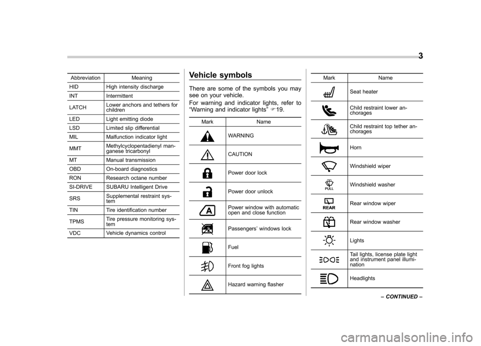
Abbreviation Meaning
HID High intensity discharge
INT Intermittent
LATCH Lower anchors and tethers for children
LED Light emitting diode
LSD Limited slip differential
MIL Malfunction indicator light MMT Methylcyclopentadienyl man-
ganese tricarbonyl
MT Manual transmission
OBD On-board diagnostics
RON Research octane number
SI-DRIVE SUBARU Intelligent Drive SRS Supplemental restraint sys- tem
TIN Tire identification number TPMS Tire pressure monitoring sys- tem
VDC Vehicle dynamics control Vehicle symbols
There are some of the symbols you may
see on your vehicle.
For warning and indicator lights, refer to “
Warning and indicator lights ”F 19.
Mark Name
WARNING
CAUTION
Power door lock
Power door unlock
Power window with automatic
open and close function
Passengers ’windows lock
Fuel
Front fog lights
Hazard warning flasher Mark Name
Seat heater
Child restraint lower an-
chorages
Child restraint top tether an-
chorages
Horn
Windshield wiper
Windshield washer
Rear window wiper
Rear window washer
Lights
Tail lights, license plate light
and instrument panel illumi-nation
Headlights3
– CONTINUED –
Page 22 of 474

&Warning and indicator lights
Mark Name Page
Seatbelt warning light 3-9
Front passenger ’s
seatbelt warning light 3-9
SRS airbag system
warning light3-11
CHECK ENGINE warn-
ing light/Malfunction in-
dicator light3-12
Coolant temperature
low indicator light/Cool-
ant temperature high
warning light3-13
Charge warning light 3-14
Oil pressure warning light
3-14
Engine oil level warning light3-14
AT OIL TEMP warning
light (AT and CVT mod- els)3-14
/ABS warning light 3-16 Mark Name Page
/Brake system warning light
3-17
Hill Holder indicator light3-19
Door open indicator light
3-19
Low fuel warning light 3-19
All-Wheel Drive warn-
ing light (AT and CVT models)3-20
Vehicle Dynamics Con-
trol warning light/Vehi-
cle Dynamics Control
operation indicator light3-20
Vehicle Dynamics Con-
trol OFF indicator light
3-21
Security indicator light 3-21
Turn signal indicator lights
3-22
High beam indicator light3-22
Front fog light indicator
light (if equipped)3-23Mark Name Page
Cruise control indicator light
3-23
Cruise control set indi-
cator light3-23
Headlight indicator light 3-23
Low tire pressure
warning light
(U.S. spec. models)3-15
/Front passenger
’s fron-
tal airbag ON indicator light 3-11
/Front passenger
’s fron-
tal airbag OFF indicator light 3-11
Shift-up indicator 3-22
Windshield washer fluid
warning light
3-1919
Page 23 of 474

20
Function settings
A SUBARU dealer can change the settings of the functions shown in the following table to meet your personal requirements. Contact
the nearest SUBARU dealer for details.Item Function Possible settings Default setting Page
Alarm system Alarm system Operation/Non-operation Operation 2-15 Monitoring start delay time (after closure
of doors) 0 second/30 seconds 30 seconds 2-17
Impact sensor operation (only models
with shock sensors (dealer option)) Operation/Non-operation Non-operation 2-19
Passive arming Operation/Non-operation Non-operation 2-18
Map light/Dome light/Cargo area light illumination ON/OFF OFF 2-15
Remote keyless entry sys-tem Hazard warning flasher Operation/Non-operation Operation 2-7
Audible signal Operation/Non-operation Operation 2-10
Key lock-in prevention Key lock-in prevention Operation/Non-operation Operation 2-6
Defogger and deicer system
for models with the automatic
climate control system Rear window defogger, outside mirror
defogger and windshield wiper deicer
Operation for 15 minutes/
Continuous operationOperation for 15 minutes 3-34
Map light/Dome light/Cargo
area light Operation of map light/Dome light/Cargo
area light OFF delay timer OFF/Short/Normal/Long Long 6-2
Battery drainage preventionfunction Battery drainage prevention function Operation/Non-operation Operation 2-6
Seatbelt warning Sounds a chime while driving Operation/Non-operation Operation 1-14
Auto on/off headlights Sensitivity of the operation of the auto on/ off headlights Low/Normal/High/Very high Normal 3-27
Page 108 of 474
!Disarming the system
To disarm the system, briefly press the “
” button on the transmitter.
& Tripped sensor identification
The security indicator light flashes when
the alarm system has been triggered.
Also, the number of flashes indicates the
location of unauthorized intrusion or the
severity of impact on the vehicle.
When the ignition switch is turned to the “ ON ”position, the indicator light will
illuminate for 1 second and then flash asfollows: . When a door or rear gate (Outback)
was opened: 5 times. When the trunk (Legacy) was opened:
4 times . When a strong impact or multiple
impacts were sensed: twice (only models
with shock sensors (dealer option)) . When a light impact was sensed: once
(only models with shock sensors (dealer option))
& Shock sensors (dealer op- tion)
The shock sensors trigger the alarm
system when they sense impacts applied
to the vehicle and when any of their
electric wires is cut. The alarm system causes the horn to sound and the turn
signal lights to flash for a short time when
the sensed impact is weak, but it warns of
a strong impact or multiple impacts by
sounding the horn and flashing the turn
signal lights, both lasting approximately 30seconds.
If you desire, your SUBARU dealer can
connect them and set them for activation
or deactivation.
NOTE . The shock sensors are not always
able to sense impacts caused by break-
ing in, and cannot sense an impact that
does not cause vibration (such as
breaking the glass using a rescuehammer).. The shock sensors may sense vi-
bration like those shown in the follow-
ing and trigger the alarm system.
Select the settings of the alarm system
and shock sensors appropriately de-
pending on where you usually park
your vehicle.Examples:
–Vibration from construction site
– Vibration in multistory car park
– Vibration from trains
. You can have the sensitivity of the
shock sensors adjusted to your pre-
ference by your SUBARU dealer. Child safety locksWARNING
Always turn the child safety locks to the “LOCK ”position when children
sit on the rear seat. Serious injury
could result if a child accidentally
opens the door and falls out.
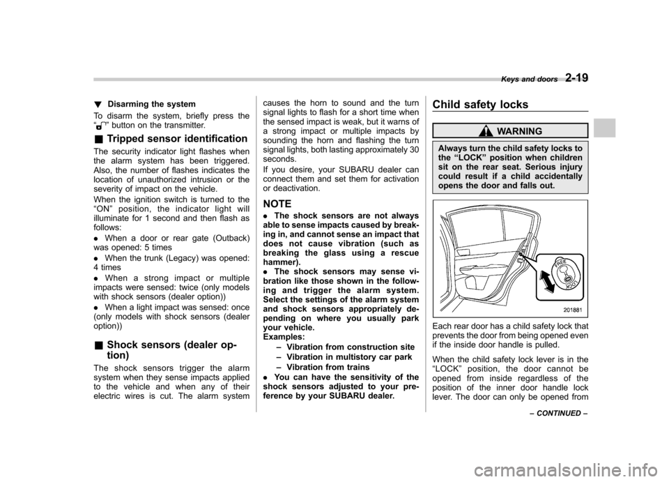
Each rear door has a child safety lock that
prevents the door from being opened even
if the inside door handle is pulled.
When the child safety lock lever is in the “ LOCK ”position, the door cannot be
opened from inside regardless of the
position of the inner door handle lock
lever. The door can only be opened from Keys and doors
2-19
– CONTINUED –
Page 120 of 474
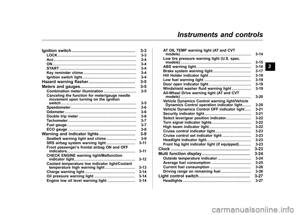
Ignition switch..................................................... 3-3
LOCK .................................................................. 3-3
Acc..................................................................... 3-4
ON...................................................................... 3-4
START ................................................................ 3-4
Key reminder chime ............................................ 3-4
Ignition switch light ............................................. 3-4
Hazard warning flasher ....................................... 3-5
Meters and gauges. ............................................. 3-5
Combination meter illumination ........................... 3-5
Canceling the function for meter/gauge needle movement upon turning on the ignition switch ............................................................... 3-5
Speedometer ....................................................... 3-6
Odometer ............................................................ 3-6
Double trip meter ................................................ 3-6
Tachometer ......................................................... 3-7
Fuel gauge .......................................................... 3-7
ECO gauge ......................................................... 3-8
Warning and indicator lights .............................. 3-9
Seatbelt warning light and chime ......................... 3-9
SRS airbag system warning light ........................ 3-11
Front passenger ’s frontal airbag ON and OFF
indicators ......................................................... 3-11
CHECK ENGINE warning light/Malfunction indicator light ................................................... 3-12
Coolant temperature low indicator light/Coolant temperature high warning light ......................... 3-13
Charge warning light .......................................... 3-14
Oil pressure warning light .................................. 3-14
Engine low oil level warning light ....................... 3-14AT OIL TEMP warning light (AT and CVT
models) ........................................................... 3-14
Low tire pressure warning light (U.S. spec. models) ........................................................... 3-15
ABS warning light .............................................. 3-16
Brake system warning light ................................ 3-17
Hill Holder indicator light ................................... 3-19
Low fuel warning light ....................................... 3-19
Door open indicator light ................................... 3-19
Windshield washer fluid warning light ................ 3-19
All-Wheel Drive warning light (AT and CVT models) ........................................................... 3-20
Vehicle Dynamics Control warning light/Vehicle Dynamics Control operation indicator light .. ..... 3-20
Vehicle Dynamics Control OFF indicator light ..... 3-21
Security indicator light ....................................... 3-21
Select lever/gear position indicator ..................... 3-22
Turn signal indicator lights ................................. 3-22
High beam indicator light ................................... 3-22
Cruise control indicator light .............................. 3-23
Cruise control set indicator light ........................ 3-23
Headlight indicator light ..................................... 3-23
Front fog light indicator light (if equipped) ..... ..... 3-23
Clock .................................................................. 3-23
Multi function display ........................................ 3-24
Outside temperature indicator .. .......................... 3-24
Average fuel consumption ................................. 3-25
Current fuel consumption .................................. 3-26
Driving range on remaining fuel ......................... 3-26
Light control switch ........................................... 3-27
Headlights ......................................................... 3-27
Instruments and controls
3
Page 124 of 474
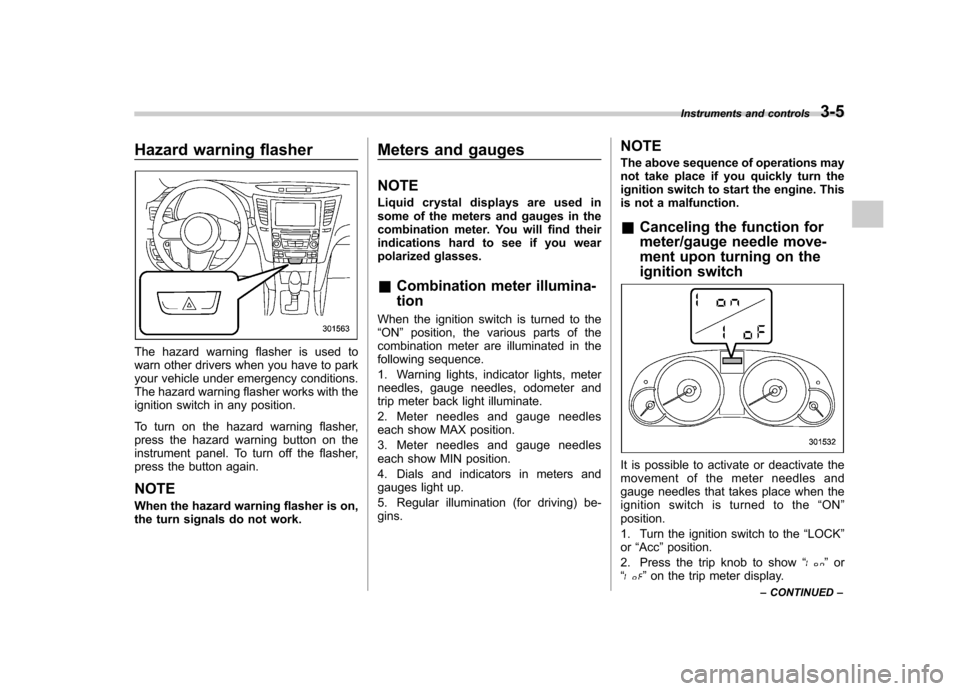
Hazard warning flasher
The hazard warning flasher is used to
warn other drivers when you have to park
your vehicle under emergency conditions.
The hazard warning flasher works with the
ignition switch in any position.
To turn on the hazard warning flasher,
press the hazard warning button on the
instrument panel. To turn off the flasher,
press the button again. NOTE
When the hazard warning flasher is on,
the turn signals do not work.Meters and gauges NOTE
Liquid crystal displays are used in
some of the meters and gauges in the
combination meter. You will find their
indications hard to see if you wear
polarized glasses. &
Combination meter illumina- tion
When the ignition switch is turned to the “ ON ”position, the various parts of the
combination meter are illuminated in the
following sequence.
1. Warning lights, indicator lights, meter
needles, gauge needles, odometer and
trip meter back light illuminate.
2. Meter needles and gauge needles
each show MAX position.
3. Meter needles and gauge needles
each show MIN position.
4. Dials and indicators in meters and
gauges light up.
5. Regular illumination (for driving) be- gins. NOTE
The above sequence of operations may
not take place if you quickly turn the
ignition switch to start the engine. This
is not a malfunction. &
Canceling the function for
meter/gauge needle move-
ment upon turning on the
ignition switch
It is possible to activate or deactivate the
movement of the meter needles and
gauge needles that takes place when the
ignition switch is turned to the “ON ”
position.
1. Turn the ignition switch to the “LOCK ”
or “Acc ”position.
2. Press the trip knob to show “
”or
“” on the trip meter display. Instruments and controls
3-5
– CONTINUED –
Page 128 of 474

Warning and indicator lights
Several of the warning and indicator lights
illuminate momentarily and then go out
when the ignition switch is initially turned
to the“ON ”position. This permits check-
ing the operation of the bulbs.
Apply the parking brake and turn the
ignition switch to the “ON ”position. For
the system check, the following lights
illuminate and turn off after several sec-
onds or after the engine has started:
: Seatbelt warning light (The seatbelt warning light turns off
only when the driver fastens the seatbelt.)
: Front passenger ’s seatbelt warning
light
(The seatbelt warning light turns off
only when the front seat passenger
fastens the seatbelt.)
: SRS airbag system warning light
ON /
: Front passenger ’s frontal airbag
ON indicator light
/: Front passenger ’s frontal airbag
OFF indicator light
: CHECK ENGINE warning light/Mal- function indicator light
: Coolant temperature high warning light
: Charge warning light
: Oil pressure warning light
: Engine low oil level warning light
: Windshield washer fluid warning light
: AT OIL TEMP warning light(AT and CVT models)
/: ABS warning light
: Vehicle Dynamics Control warning light/Vehicle Dynamics Control opera-
tion indicator light
: Vehicle Dynamics Control OFF indica-
tor light
/: Brake system warning light
: Hill Holder indicator light
: All-Wheel Drive warning light (AT andCVT models)
: Low tire pressure warning light (U.S. spec. models)
: Low fuel warning light
: Door open indicator light
: Cruise control indicator light
: Cruise control set indicator light
: Select lever/gear position indicator
If any lights fail to illuminate, it indicates a
burned-out bulb or a malfunction of the
corresponding system.
Consult your authorized SUBARU dealer
for repair. & Seatbelt warning light
and chime
Your vehicle is equipped with a seatbelt
warning device at the driver ’s and front
passenger ’s seat, as required by current
safety standards.
With the ignition switch turned to the “ON ”
position, this device reminds the driver
and front passenger to fasten their seat-
belts by the warning lights in the locations
indicated in the following illustration and achime. Instruments and controls
3-9
– CONTINUED –
Page 137 of 474

3-18Instruments and controls
flash after the electronic parking brake
is frequently applied and released.
However, the electronic parking brake
system is not malfunctioning if the light
turns off for a short period of time.
This light has the following functions: ! Parking brake warning
The light illuminates with the parking
brake applied while the ignition switch is
in the “ON ”position. It turns off when the
parking brake is released. ! Brake fluid level warning
This light illuminates when the brake fluid
level has dropped to near the “MIN ”level
of the brake fluid reservoir with the ignition
switch in the “ON ”position and with the
parking brake released.
If the brake system warning light should
illuminate while driving (with the parking
brake released and with the ignition switch
positioned in “ON ”), it could be an indica-
tion of leaking of brake fluid or worn brake
pads. If this occurs, immediately stop the
vehicle at the nearest safe place and
check the brake fluid level. If the fluid level
is below the “MIN ”mark in the reservoir,
do not drive the vehicle. Have the vehicle
towed to the nearest SUBARU dealer for
repair. !
Electronic Brake Force Distribution
(EBD) system warning
The brake system warning light also
illuminates if a malfunction occurs in the
EBD system. In that event, it illuminates
together with the ABS warning light.
The EBD system may be malfunctioning if
the brake system warning light and ABS
warning light illuminate simultaneously
during driving.
Even if the EBD system fails, the conven-
tional braking system will still function.
However, the rear wheels will be more
prone to locking when the brakes are
applied harder than usual and the vehi-cle ’s motion may therefore become some-
what harder to control.
If the brake system warning light and ABS
warning light illuminate simultaneously,
take the following steps:
1. Stop the vehicle in the nearest safe,
flat place.
2. Shut down the engine, then restart it.
3. Release the parking brake. If both
warning lights turn off, the EBD system
may be malfunctioning.
Drive carefully to the nearest SUBARU
dealer and have the system inspected.
4. If both warning lights illuminate again
and remain illuminated after the engine
has been restarted, shut down the engine again, apply the parking brake, and check
the brake fluid level. Refer to
“Brake fluid ”
F 11-25.
5. If the brake fluid level is not below the“ MIN ”mark, the EBD system may be
malfunctioning. Drive carefully to the
nearest SUBARU dealer and have the
system inspected.
6. If the brake fluid level is below the “ MIN ”mark, DO NOT drive the vehicle.
Instead, have the vehicle towed to the
nearest SUBARU dealer for repair. ! Electronic parking brake system warning
The brake system warning light flashes
when the electronic parking brake system
is malfunctioning. If the warning light
flashes, promptly park in a safe location
as soon as possible and contact your
SUBARU dealer.
The brake system warning light remains
illuminated when the parking brake cannot
be released even if the parking brake
switch is pulled. For details, refer to“ Electronic parking brake ”F 7-31.
! Parking brake apply inhibit warning
The brake system warning light flashes for
10 seconds and a chirp sound will be
heard if the parking brake switch is
operated when the parking brake cannot
Page 142 of 474

&Cruise control indica-
tor light
This light illuminates when the “CRUISE ”
main switch is pressed to activate the
cruise control function. NOTE . If you press the main switch button
while turning the ignition switch “ON ”,
the cruise control function is deacti-
vated and the “CRUISE ”indicator light
flashes. To reactivate the cruise control
function, turn the ignition switch back
to the “Acc ”or “LOCK ”position, and
then turn it again to the “ON ”position.
. If this indicator light and the CHECK
ENGINE warning light/malfunction in-
dicator light flash simultaneously dur-
ing driving, have the vehicle checked
by your nearest SUBARU dealer.
& Cruise control set in-
dicator light
This light illuminates when vehicle speed
has been set to use the cruise controlfunction. &
Headlight indicator light
This indicator light illuminates under the
following conditions. .when the light switch is turned to the
“
” or “”position
. when the light switch is in the “AUTO ”
position and the headlights illuminate automatically & Front fog light indicator
light (if equipped)
This indicator light illuminates while the
front fog lights are illuminated. Clock NOTE
Your SUBARU dealer can change the
settings of activating/deactivating the
automatic adjustment of the clock by
the GPS (Global Positioning System)
(for models with the genuine SUBARU
navigation system). Contact your
SUBARU dealer for details.
The clock shows the time while the
ignition switch is in the
“Acc ”or “ON ”
position.
To adjust the time shown by the clock,
press the “+ ” button or the “� ” button. If
you press the “+ ” button, the indicated
time will change in one-minute incre-
ments. If you press the “� ” button, the
Instruments and controls
3-23
– CONTINUED –
Page 147 of 474
3-28Instruments and controls
CAUTION
If any object is placed on or near the
sensor, the sensor may not detect
the level of the ambient light cor-
rectly and the auto on/off headlights
may not operate properly.
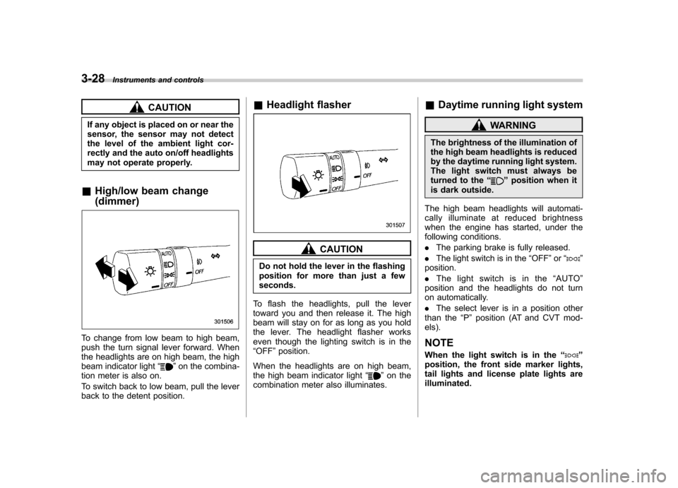
& High/low beam change (dimmer)
To change from low beam to high beam,
push the turn signal lever forward. When
the headlights are on high beam, the high
beam indicator light “
”on the combina-
tion meter is also on.
To switch back to low beam, pull the lever
back to the detent position. &
Headlight flasher
CAUTION
Do not hold the lever in the flashing
position for more than just a fewseconds.
To flash the headlights, pull the lever
toward you and then release it. The high
beam will stay on for as long as you hold
the lever. The headlight flasher works
even though the lighting switch is in the“ OFF ”position.
When the headlights are on high beam,
the high beam indicator light “
”on the
combination meter also illuminates. &
Daytime running light system
WARNING
The brightness of the illumination of
the high beam headlights is reduced
by the daytime running light system.
The light switch must always be
turned to the “
”position when it
is dark outside.
The high beam headlights will automati-
cally illuminate at reduced brightness
when the engine has started, under the
following conditions. . The parking brake is fully released.
. The light switch is in the “OFF ”or “
”
position. . The light switch is in the “AUTO ”
position and the headlights do not turn
on automatically. . The select lever is in a position other
than the “P ” position (AT and CVT mod-
els).
NOTE
When the light switch is in the “
”
position, the front side marker lights,
tail lights and license plate lights areilluminated.