oil temperature SUBARU TRIBECA 2008 Owners Manual
[x] Cancel search | Manufacturer: SUBARU, Model Year: 2008, Model line: TRIBECA, Model: SUBARU TRIBECA 2008Pages: 409, PDF Size: 5.75 MB
Page 21 of 409
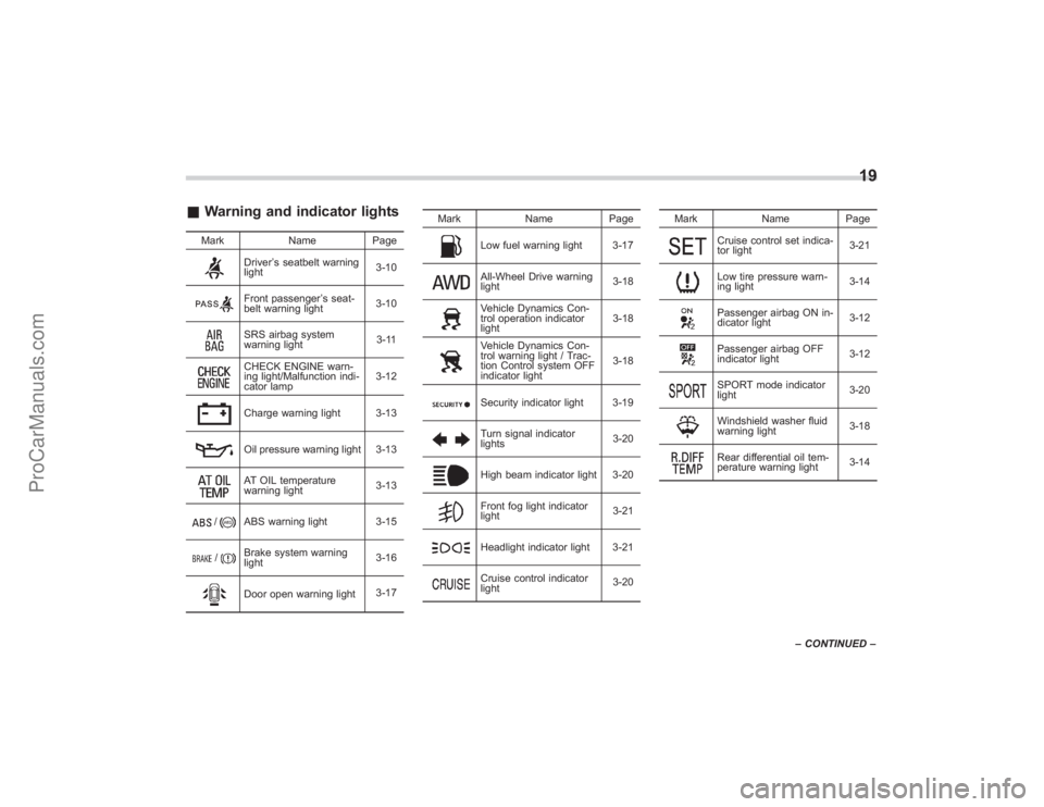
&Warning and indicator lights
Mark NamePage
Driver’s seatbelt warning
light 3-10Front passenger
’s seat-
belt warning light 3-10SRS airbag system
warning light 3-11CHECK ENGINE warn-
ing light/Malfunction indi-
cator lamp3-12Charge warning light 3-13Oil pressure warning light 3-13AT OIL temperature
warning light
3-13
/
ABS warning light 3-15
/
Brake system warning
light3-16Door open warning light
3-17Mark Name Page
Low fuel warning light 3-17All-Wheel Drive warning
light
3-18Vehicle Dynamics Con-
trol operation indicator
light3-18Vehicle Dynamics Con-
trol warning light / Trac-
tion Control system OFF
indicator light3-18Security indicator light 3-19Turn signal indicator
lights
3-20High beam indicator light 3-20Front fog light indicator
light3-21Headlight indicator light 3-21Cruise control indicator
light3-20Mark Name Page
Cruise control set indica-
tor light
3-21Low tire pressure warn-
ing light3-14Passenger airbag ON in-
dicator light
3-12Passenger airbag OFF
indicator light3-12SPORT mode indicator
light
3-20Windshield washer fluid
warning light3-18Rear differential oil tem-
perature warning light3-14
19
–
CONTINUED –
ProCarManuals.com
Page 121 of 409
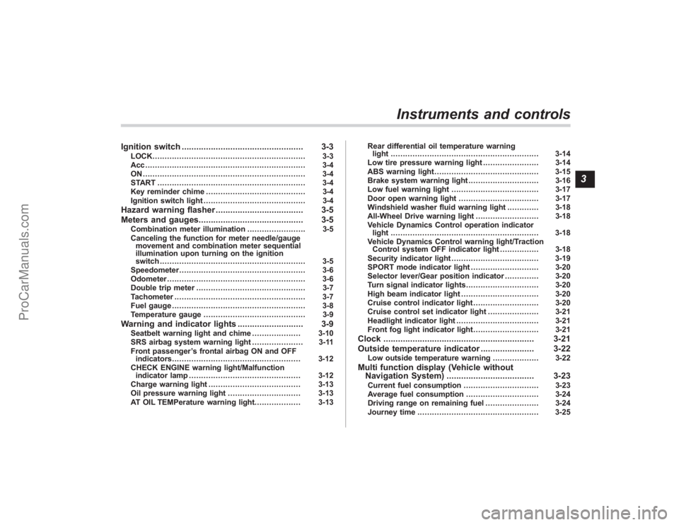
Ignition switch.................................................. 3-3
LOCK............................................................... 3-3
Acc.................................................................. 3-4
ON................................................................... 3-4
START ............................................................. 3-4
Key reminder chime ......................................... 3-4
Ignition switch light .......................................... 3-4
Hazard warning flasher .................................... 3-5
Meters and gauges. .......................................... 3-5
Combination meter illumination ........................ 3-5
Canceling the function for meter needle/gauge movement and combination meter sequential
illumination upon turning on the ignition
switch ............................................................ 3-5
Speedometer .................................................... 3-6
Odometer ......................................................... 3-6
Double trip meter ............................................. 3-7
Tachometer ...................................................... 3-7
Fuel gauge ....................................................... 3-8
Temperature gauge .......................................... 3-9
Warning and indicator lights ........................... 3-9
Seatbelt warning light and chime .................... 3-10
SRS airbag system warning light ..................... 3-11
Front passenger ’s frontal airbag ON and OFF
indicators ..................................................... 3-12
CHECK ENGINE warning light/Malfunction indicator lamp .............................................. 3-12
Charge warning light ...................................... 3-13
Oil pressure warning light .............................. 3-13
AT OIL TEMPerature warning light. .................. 3-13Rear differential oil temperature warning
light ............................................................. 3-14
Low tire pressure warning light ....................... 3-14
ABS warning light ........................................... 3-15
Brake system warning light ............................. 3-16
Low fuel warning light .................................... 3-17
Door open warning light ................................. 3-17
Windshield washer fluid warning light ............. 3-18
All-Wheel Drive warning light .......................... 3-18
Vehicle Dynamics Control operation indicator light ............................................................. 3-18
Vehicle Dynamics Control warning light/Traction Control system OFF indicator light ................ 3-18
Security indicator light .................................... 3-19
SPORT mode indicator light ............................ 3-20
Selector lever/Gear position indicator .............. 3-20
Turn signal indicator lights .............................. 3-20
High beam indicator light ................................ 3-20
Cruise control indicator light ........................... 3-20
Cruise control set indicator light ..................... 3-21
Headlight indicator light .................................. 3-21
Front fog light indicator light ........................... 3-21
Clock.............................................................. 3-21
Outside temperature indicator ...................... 3-22
Low outside temperature warning ................... 3-22
Multi function display (Vehicle without
Navigation System) .................................... 3-23
Current fuel consumption ............................... 3-23
Average fuel consumption .............................. 3-24
Driving range on remaining fuel ...................... 3-24
Journey time .................................................. 3-25
Instruments and controls
3
ProCarManuals.com
Page 129 of 409
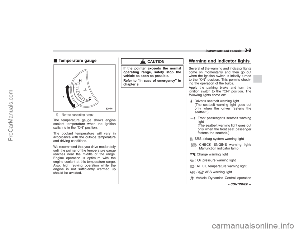
&Temperature gauge1) Normal operating rangeThe temperature gauge shows engine
coolant temperature when the ignition
switch is in the “ON”position.
The coolant temperature will vary in
accordance with the outside temperature
and driving conditions.
We recommend that you drive moderately
until the pointer of the temperature gauge
reaches near the middle of the range.
Engine operation is optimum with the
engine coolant at this temperature range.
Also, high revving operation while the
engine is not sufficiently warmed up
should be avoided.
CAUTION
If the pointer exceeds the normal
operating range, safely stop the
vehicle as soon as possible.
Refer to “In case of emergency ”in
chapter 9.
Warning and indicator lightsSeveral of the warning and indicator lights
come on momentarily and then go out
when the ignition switch is initially turned
to the “ON ”position. This permits check-
ing the operation of the bulbs.
Apply the parking brake and turn the
ignition switch to the “ON ”position. The
following lights come on:
: Driver ’s seatbelt warning light
(The seatbelt warning light goes out
only when the driver fastens the
seatbelt.): Front passenger ’s seatbelt warning
light
(The seatbelt warning light goes out
only when the front seat passenger
fastens the seatbelt.): SRS airbag system warning light: CHECK ENGINE warning light/ Malfunction indicator lamp: Charge warning light: Oil pressure warning light: AT OIL temperature warning light/
: ABS warning light
: Vehicle Dynamics Control operation
Instruments and controls
3-9
–CONTINUED –
ProCarManuals.com
Page 130 of 409
3-10
Instruments and controls
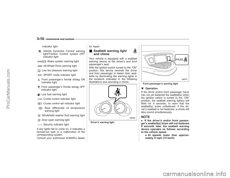
indicator light: Vehicle Dynamics Control warninglight/Traction Control system OFF
indicator light/
: Brake system warning light
: All-Wheel Drive warning light: Low tire pressure warning light: SPORT mode indicator light: Front passenger ’s frontal airbag ON
indicator light: Front passenger ’s frontal airbag OFF
indicator light: Low fuel warning light: Cruise control indicator light: Cruise control set indicator light: Rear differential oil temperature warning light: Windshield washer fluid warning light: Door open warning light: Security indicator light
If any lights fail to come on, it indicates a
burned-out bulb or a malfunction of the
corresponding system.
Consult your authorized SUBARU dealer for repair.
&
Seatbelt warning light
and chime
Your vehicle is equipped with a seatbelt
warning device at the driver
’s and front
passenger ’s seat.
With the ignition switch turned to the “ON”
position, this device reminds the driver
and front passenger to fasten their seat-
belts by illuminating the warning lights in
the locations indicated in the following
illustrations and sounding a chime.Driver ’s warning light
Front passenger ’s warning light! Operation
If the driver and/or front passenger have/
has not yet fastened the seatbelt(s) when
the ignition switch is turned to the “ON”
position, the seatbelt warning light(s) will
flash for 6 seconds, to warn that the
seatbelt(s) is/are unfastened. If the dri-
ver ’s seatbelt is not fastened, a chime will
also sound simultaneously.NOTE. If the driver ’s and/or front passen-
ger ’s seatbelt(s) is/are still not fastened
6 seconds later, the seatbelt warning
device operates as follows according
to the vehicle speed.
.At speeds lower than approxi-
mately 9 mph (15 km/h)
ProCarManuals.com
Page 133 of 409
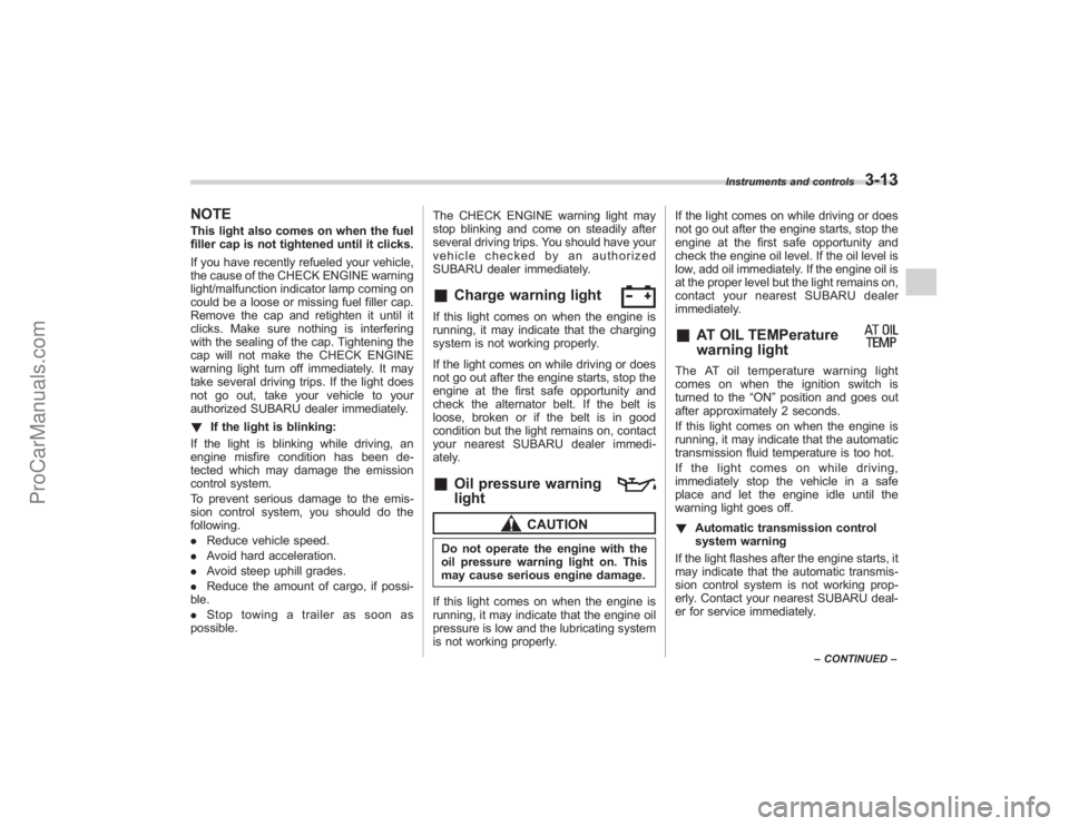
NOTEThis light also comes on when the fuel
filler cap is not tightened until it clicks.
If you have recently refueled your vehicle,
the cause of the CHECK ENGINE warning
light/malfunction indicator lamp coming on
could be a loose or missing fuel filler cap.
Remove the cap and retighten it until it
clicks. Make sure nothing is interfering
with the sealing of the cap. Tightening the
cap will not make the CHECK ENGINE
warning light turn off immediately. It may
take several driving trips. If the light does
not go out, take your vehicle to your
authorized SUBARU dealer immediately.
!If the light is blinking:
If the light is blinking while driving, an
engine misfire condition has been de-
tected which may damage the emission
control system.
To prevent serious damage to the emis-
sion control system, you should do the
following.
. Reduce vehicle speed.
. Avoid hard acceleration.
. Avoid steep uphill grades.
. Reduce the amount of cargo, if possi-
ble.
. Stop towing a trailer as soon as
possible. The CHECK ENGINE warning light may
stop blinking and come on steadily after
several driving trips. You should have your
vehicle checked by an authorized
SUBARU dealer immediately.
&
Charge warning light
If this light comes on when the engine is
running, it may indicate that the charging
system is not working properly.
If the light comes on while driving or does
not go out after the engine starts, stop the
engine at the first safe opportunity and
check the alternator belt. If the belt is
loose, broken or if the belt is in good
condition but the light remains on, contact
your nearest SUBARU dealer immedi-
ately.&
Oil pressure warning
light
CAUTION
Do not operate the engine with the
oil pressure warning light on. This
may cause serious engine damage.
If this light comes on when the engine is
running, it may indicate that the engine oil
pressure is low and the lubricating system
is not working properly. If the light comes on while driving or does
not go out after the engine starts, stop the
engine at the first safe opportunity and
check the engine oil level. If the oil level is
low, add oil immediately. If the engine oil is
at the proper level but the light remains on,
contact your nearest SUBARU dealer
immediately.
&
AT OIL TEMPerature
warning light
The AT oil temperature warning light
comes on when the ignition switch is
turned to the
“ON”position and goes out
after approximately 2 seconds.
If this light comes on when the engine is
running, it may indicate that the automatic
transmission fluid temperature is too hot.
If the light comes on while driving,
immediately stop the vehicle in a safe
place and let the engine idle until the
warning light goes off.
! Automatic transmission control
system warning
If the light flashes after the engine starts, it
may indicate that the automatic transmis-
sion control system is not working prop-
erly. Contact your nearest SUBARU deal-
er for service immediately.
Instruments and controls
3-13
– CONTINUED –
ProCarManuals.com
Page 134 of 409
3-14
Instruments and controls
&
Rear differential oil
temperature warning
light
CAUTION
Reduce vehicle speed and park the
vehicle in a safe place as soon as
possible if the R.DIFF TEMP light
comes on. Continued driving with
this light on can damage the rear
differential and other parts of the
powertrain.
If this light comes on when the engine is
running, it may indicate that the rear
differential oil temperature is too hot.
If the light comes on while driving, reduce
vehicle speed and stop the vehicle at the
nearest safe place.
Park the vehicle for several minutes. After
the light goes out, you can start driving.
If the light does not go out, contact the
nearest SUBARU dealer for service.NOTE. If the tire pressures are not correct
and/or the tires are not all the same
size and brand, the rear differential will
be heavily loaded when the vehicle is
driven, resulting in an abnormally high
oil temperature. .
The rear differential oil will deterio-
rate if its temperature increases en-
ough for the rear differential oil tem-
perature warning light to come on. It is
advisable to have the rear differential
oil replaced as soon as possible.
&
Low tire pressure
warning light
When the ignition switch is turned to the
“ON ”position, the low tire pressure warn-
ing light will come on for approximately 2
seconds to check that the tire pressure
monitoring system (TPMS) is functioning
properly. If there is no problem and all tires
are properly inflated, the light will go out.
Each tire, including the spare (if provided),
should be checked monthly when cold
and inflated to the inflation pressure
recommended by the vehicle manufac-
turer on the vehicle placard or tire inflation
pressure label. (If your vehicle has tires of
a different size than the size indicated on
the vehicle placard or tire inflation pres-
sure label, you should determine the
proper inflation pressure for those tires.)
As an added safety feature, your vehicle
has been equipped with a tire pressure
monitoring system (TPMS) that illuminates
a low tire pressure telltale when one or
more of your tires is significantly under- inflated. Accordingly, when the low tire
pressure telltale illuminates, you should
stop and check your tires as soon as
possible, and inflate them to the proper
pressure. Driving on a significantly under-
inflated tire causes the tire to overheat and
can lead to tire failure. Under-inflation also
reduces fuel efficiency and tire tread life,
and may affect the vehicle
’s handling and
stopping ability.
Please note that the TPMS is not a
substitute for proper tire maintenance,
and it is the driver ’s responsibility to
maintain correct tire pressure, even if
under-inflation has not reached the level
to trigger illumination of the TPMS low tire
pressure telltale.
Your vehicle has also been equipped with
a TPMS malfunction indicator to indicate
when the system is not operating properly.
The TPMS malfunction indicator is com-
bined with the low tire pressure telltale.
When the system detects a malfunction,
the telltale will flash for approximately one
minute and then remain continuously
illuminated. This sequence will continue
upon subsequent vehicle start-ups as long
as the malfunction exists. When the
malfunction indicator is illuminated, the
system may not be able to detect or signal
low tire pressure as intended. TPMS
malfunctions may occur for a variety of
ProCarManuals.com
Page 163 of 409
Ventilator........................................................... 4-2
Air flow............................................................ 4-2
Ventilator ......................................................... 4-4
Automatic climate control system .................. 4-5
Control panel................................................... 4-5
Rear air conditioner (if equipped) ...................... 4-8
Temperature sensors ........................................ 4-9
Operating tips for heater and air
conditioner ................................................... 4-10
Cleaning ventilator grille ................................. 4-10
Efficient cooling after parking in direct sunlight ....................................................... 4-10 Lubrication oil circulation in the refrigerant
circuit ........................................................... 4-10
Checking air conditioning system before summer season ......................................................... 4-10
Cooling and dehumidifying in high humidity and low temperature weather conditions .............. 4-10
Air conditioner compressor shut-off when engine is heavily loaded ........................................... 4-10
Refrigerant for your climate control system ......................................................... 4-10
Air filtration system ........................................ 4-11
Replacing the air filter ..................................... 4-11
Climate control
4
ProCarManuals.com
Page 172 of 409
4-10
Climate control
Operating tips for heater and
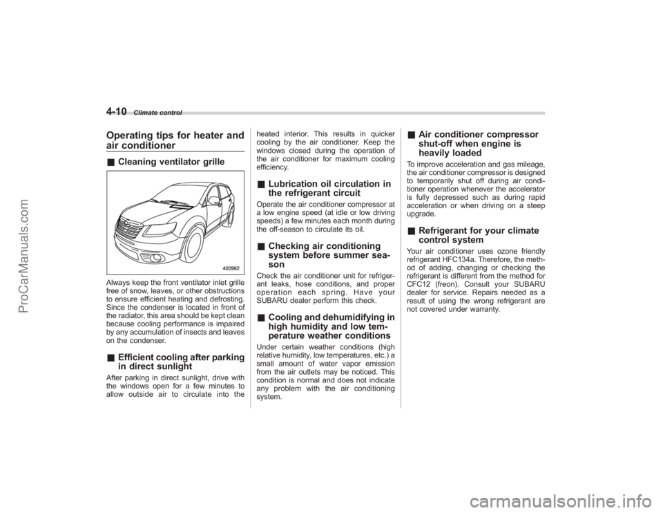
air conditioner&Cleaning ventilator grilleAlways keep the front ventilator inlet grille
free of snow, leaves, or other obstructions
to ensure efficient heating and defrosting.
Since the condenser is located in front of
the radiator, this area should be kept clean
because cooling performance is impaired
by any accumulation of insects and leaves
on the condenser.&Efficient cooling after parking
in direct sunlightAfter parking in direct sunlight, drive with
the windows open for a few minutes to
allow outside air to circulate into the heated interior. This results in quicker
cooling by the air conditioner. Keep the
windows closed during the operation of
the air conditioner for maximum cooling
efficiency.
&
Lubrication oil circulation in
the refrigerant circuitOperate the air conditioner compressor at
a low engine speed (at idle or low driving
speeds) a few minutes each month during
the off-season to circulate its oil.&Checking air conditioning
system before summer sea-
sonCheck the air conditioner unit for refriger-
ant leaks, hose conditions, and proper
operation each spring. Have your
SUBARU dealer perform this check.&Cooling and dehumidifying in
high humidity and low tem-
perature weather conditionsUnder certain weather conditions (high
relative humidity, low temperatures, etc.) a
small amount of water vapor emission
from the air outlets may be noticed. This
condition is normal and does not indicate
any problem with the air conditioning
system.
&Air conditioner compressor
shut-off when engine is
heavily loadedTo improve acceleration and gas mileage,
the air conditioner compressor is designed
to temporarily shut off during air condi-
tioner operation whenever the accelerator
is fully depressed such as during rapid
acceleration or when driving on a steep
upgrade.&Refrigerant for your climate
control systemYour air conditioner uses ozone friendly
refrigerant HFC134a. Therefore, the meth-
od of adding, changing or checking the
refrigerant is different from the method for
CFC12 (freon). Consult your SUBARU
dealer for service. Repairs needed as a
result of using the wrong refrigerant are
not covered under warranty.
ProCarManuals.com
Page 249 of 409
If you inadvertently have turned the igni-
tion switch to the“LOCK”position with the
selector lever in the “N”position, proceed
as follows. By referring to the “Shift lock
release ”section in this chapter, remove
the cover. Then, with a screwdriver in-
serted into the hole, move the selector
lever to the “P”position while pressing the
release button. If the selector lever re-
verse inhibiting function fails, have the
vehicle inspected by the nearest SUBARU
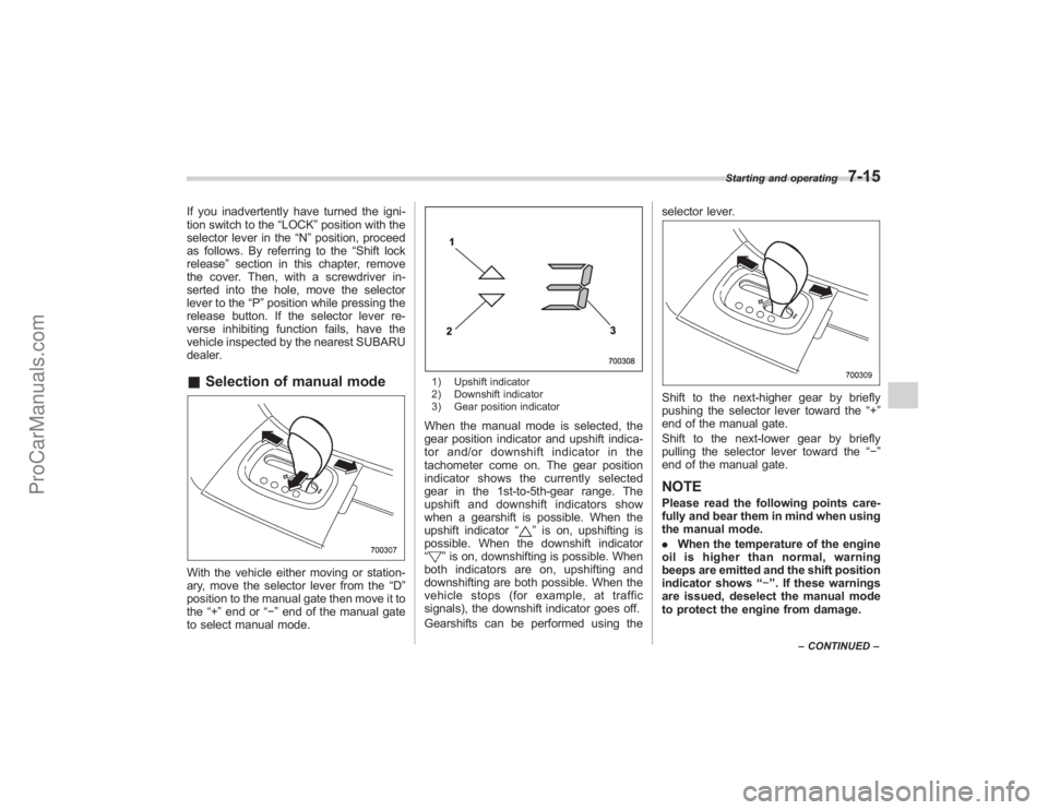
dealer.& Selection of manual modeWith the vehicle either moving or station-
ary, move the selector lever from the “D”
position to the manual gate then move it to
the “+”end or “−”end of the manual gate
to select manual mode.
1) Upshift indicator
2) Downshift indicator
3) Gear position indicatorWhen the manual mode is selected, the
gear position indicator and upshift indica-
tor and/or downshift indicator in the
tachometer come on. The gear position
indicator shows the currently selected
gear in the 1st-to-5th-gear range. The
upshift and downshift indicators show
when a gearshift is possible. When the
upshift indicator “
”is on, upshifting is
possible. When the downshift indicator
“
” is on, downshifting is possible. When
both indicators are on, upshifting and
downshifting are both possible. When the
vehicle stops (for example, at traffic
signals), the downshift indicator goes off.
Gearshifts can be performed using the selector lever.
Shift to the next-higher gear by briefly
pushing the selector lever toward the
“+”
end of the manual gate.
Shift to the next-lower gear by briefly
pulling the selector lever toward the “−”
end of the manual gate.NOTEPlease read the following points care-
fully and bear them in mind when using
the manual mode.
. When the temperature of the engine
oil is higher than normal, warning
beeps are emitted and the shift position
indicator shows “− ”. If these warnings
are issued, deselect the manual mode
to protect the engine from damage.
Starting and operating
7-15
– CONTINUED –
ProCarManuals.com
Page 250 of 409
7-16
Starting and operating
.The transmission does not automa-
tically shift up in the manual mode.
Perform gearshifts in accordance with
road conditions so that the tachometer
needle does not enter the red zone. If
the engine speed reaches a predeter-
mined level, a fuel-cut function will
operate. Shift up if this happens. Also,
the transmission may automatically
shift up to protect the engine.
. If you attempt to shift down when
the engine speed is too high, i.e., when
a downshift would push the tachometer
needle beyond the red zone, beeps will
be emitted to warn you that the down-
shift is not possible.
. If you attempt to shift up when the
vehicle speed is too low, the transmis-
sion will not respond.
. You can perform a skip-shift (for
example, from 4th to 2nd) by operating
the selector lever twice in rapid suc-
cession.
. The transmission automatically se-
lects 1st gear when the vehicle stops
moving.
. If the temperature of the automatic
transmission fluid becomes too high,
the “AT OIL TEMP ”warning light will
come on and upshifts to 5th gear will
not be possible. Immediately stop the
vehicle in a safe place and let the
engine idle until the warning light goes off.
&
Maximum speeds
WARNING
When down shifting, ensure that the
vehicle is not travelling at a speed
exceeding the Maximum Allowable
Speed for the gear which is about to
be selected. Failure to observe this
precaution can lead to engine over-
revving and this in turn can result in
engine damage.
In addition, sudden application of
engine braking caused by down
shifting when the vehicle is travel-
ling on a slippery surface can lead
to wheel locking; as a consequence,
control of the vehicle may be lost
and the risk of an accident in-
creased.
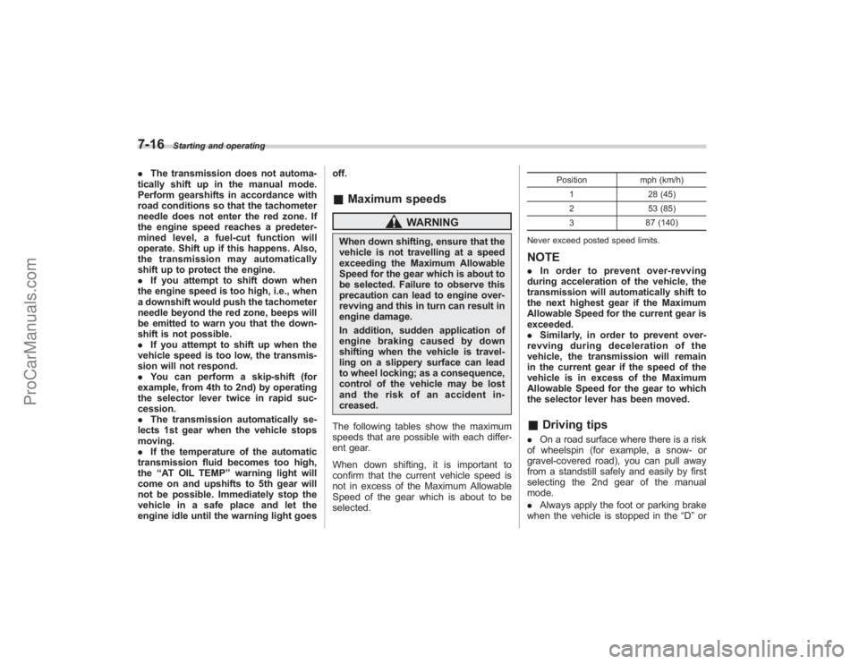
The following tables show the maximum
speeds that are possible with each differ-
ent gear.
When down shifting, it is important to
confirm that the current vehicle speed is
not in excess of the Maximum Allowable
Speed of the gear which is about to be
selected.
Position mph (km/h)
1 28 (45)
2 53 (85)
3 87 (140)
Never exceed posted speed limits.
NOTE. In order to prevent over-revving
during acceleration of the vehicle, the
transmission will automatically shift to
the next highest gear if the Maximum
Allowable Speed for the current gear is
exceeded.
. Similarly, in order to prevent over-
revving during deceleration of the
vehicle, the transmission will remain
in the current gear if the speed of the
vehicle is in excess of the Maximum
Allowable Speed for the gear to which
the selector lever has been moved.& Driving tips. On a road surface where there is a risk
of wheelspin (for example, a snow- or
gravel-covered road), you can pull away
from a standstill safely and easily by first
selecting the 2nd gear of the manual
mode.
. Always apply the foot or parking brake
when the vehicle is stopped in the “D”or
ProCarManuals.com