sport mode SUBARU TRIBECA 2010 1.G Owners Manual
[x] Cancel search | Manufacturer: SUBARU, Model Year: 2010, Model line: TRIBECA, Model: SUBARU TRIBECA 2010 1.GPages: 422, PDF Size: 12.87 MB
Page 22 of 422

&Warning and indicator lights
Mark Name Page
Driver ’s seatbelt warning
light 3-10
Front passenger
’s seat-
belt warning light 3-10
SRS airbag system
warning light 3-11
CHECK ENGINE warn-
ing light/Malfunction indi-
cator lamp3-12
Charge warning light 3-13
Oil pressure warning light 3-13
AT OIL TEMP warning light
3-13
/ABS warning light 3-15
/Brake system warning light
3-16
Door open warning light
3-17Mark Name Page
Low fuel warning light 3-17
AWD warning light 3-18
Vehicle Dynamics Con-
trol operation indicator light
3-18
Vehicle Dynamics Con-
trol warning light/Traction
Control system OFF in-
dicator light3-18
Security indicator light 3-19
Turn signal indicator lights
3-20
High beam indicator light 3-20
Front fog light indicator light3-21
Headlight indicator light 3-21
Cruise control indicator light3-20Mark Name Page
Cruise control set indica-
tor light
3-21
Low tire pressure warn-
ing light3-14
Passenger airbag ON in-
dicator light
3-12
Passenger airbag OFF
indicator light3-12
SPORT mode indicator light
3-20
Windshield washer fluid
warning light3-18
Rear differential oil tem-
perature warning light3-1419
– CONTINUED –
Page 130 of 422
Ignition switch..................................................... 3-3
LOCK .................................................................. 3-3
Acc..................................................................... 3-4
ON...................................................................... 3-4
START ................................................................ 3-4
Key reminder chime ............................................ 3-4
Ignition switch light ............................................. 3-4
Hazard warning flasher ....................................... 3-5
Meters and gauges. ............................................. 3-5
Combination meter illumination ........................... 3-5
Canceling the function for meter needle/gauge movement and combination meter sequential
illumination upon turning on the ignition switch ............................................................... 3-5
Speedometer ....................................................... 3-6
Odometer ............................................................ 3-6
Double trip meter ................................................ 3-7
Tachometer ......................................................... 3-7
Fuel gauge .......................................................... 3-8
Temperature gauge ............................................. 3-9
Warning and indicator lights .............................. 3-9
Seatbelt warning light and chime ........................ 3-10
SRS airbag system warning light ........................ 3-11
Front passenger ’s frontal airbag ON and OFF
indicators ......................................................... 3-12
CHECK ENGINE warning light/Malfunction indicator lamp .................................................. 3-12
Charge warning light .......................................... 3-13
Oil pressure warning light .................................. 3-13
AT OIL TEMP warning light ................................. 3-13 Rear differential oil temperature warning
light ................................................................ 3-14
Low tire pressure warning light .......................... 3-14
ABS warning light .............................................. 3-15
Brake system warning light ................................ 3-16
Low fuel warning light ....................................... 3-17
Door open warning light .................................... 3-17
Windshield washer fluid warning light ................ 3-18
All-Wheel Drive warning light ... .......................... 3-18
Vehicle Dynamics Control operation indicator light ................................................................ 3-18
Vehicle Dynamics Control warning light/Traction Control system OFF indicator light ................... 3-18
Security indicator light ....................................... 3-19
SPORT mode indicator light ............................... 3-20
Select lever/Gear position indicator .................... 3-20
Turn signal indicator lights ................................. 3-20
High beam indicator light ................................... 3-20
Cruise control indicator light .............................. 3-20
Cruise control set indicator light ........................ 3-21
Headlight indicator light ..................................... 3-21
Front fog light indicator light .............................. 3-21
Clock .................................................................. 3-21
Outside temperature indicator .......................... 3-22
Low outside temperature warning ...................... 3-22
Multi function display (vehicles without a genuine SUBARU navigation system) ........... 3-23
Current fuel consumption .................................. 3-23
Average fuel consumption ................................. 3-24
Driving range on remaining fuel ......................... 3-24
Journey time ..................................................... 3-25
Instruments and controls
3
Page 139 of 422
3-10Instruments and controls
: Vehicle Dynamics Control operation
indicator light
: Vehicle Dynamics Control warning light/Traction Control system OFF
indicator light
/: Brake system warning light
: AWD warning light
: Low tire pressure warning light
: SPORT mode indicator light
: Front passenger ’s frontal airbag ON
indicator light
: Front passenger ’s frontal airbag OFF
indicator light
: Low fuel warning light
: Cruise control indicator light
: Cruise control set indicator light
: Rear differential oil temperature warn-
ing light
: Windshield washer fluid warning light
: Door open warning light
If any lights do not illuminate, it indicates a
burned-out bulb or a malfunction of the
corresponding system.
Consult your authorized SUBARU dealer for repair.
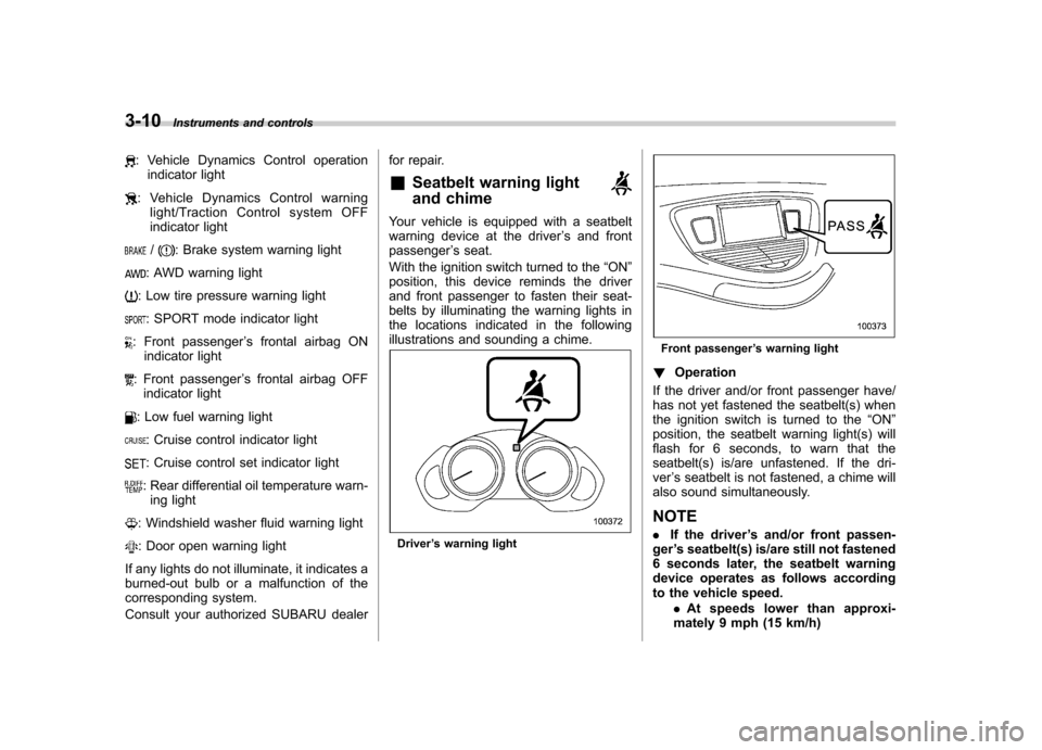
& Seatbelt warning light
and chime
Your vehicle is equipped with a seatbelt
warning device at the driver ’s and front
passenger ’s seat.
With the ignition switch turned to the “ON ”
position, this device reminds the driver
and front passenger to fasten their seat-
belts by illuminating the warning lights in
the locations indicated in the following
illustrations and sounding a chime.
Driver ’s warning light
Front passenger ’s warning light
! Operation
If the driver and/or front passenger have/
has not yet fastened the seatbelt(s) when
the ignition switch is turned to the “ON ”
position, the seatbelt warning light(s) will
flash for 6 seconds, to warn that the
seatbelt(s) is/are unfastened. If the dri-ver ’s seatbelt is not fastened, a chime will
also sound simultaneously. NOTE . If the driver ’s and/or front passen-
ger ’s seatbelt(s) is/are still not fastened
6 seconds later, the seatbelt warning
device operates as follows according
to the vehicle speed.
.At speeds lower than approxi-
mately 9 mph (15 km/h)
Page 149 of 422
3-20Instruments and controls
If the indicator light does not flash, it may
indicate that immobilizer system may be
malfunctioning. Contact your nearest
SUBARU dealer immediately.
In the event that an unauthorized key (for
example, an unauthorized duplicate) is
used, the security indicator light illumi-nates. & SPORT mode indicator light
This light illuminates when the ignition
switch is turned to the “ON ”position and
turns off after the engine has started.
When the select lever is moved to the
manual gate, the SPORT mode is se-
lected and the indicator light illuminates.
Refer to “SPORT mode ”F 7-18. &
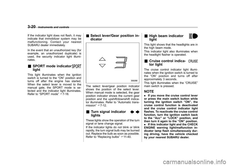
Select lever/Gear position in- dicator
The select lever/gear position indicator
shows the position of the select lever.
When manual mode is selected, the gear
position indicator shows the current gear
position and the upshift/downshift indica-
tor illuminates. Refer to “Automatic trans-
mission ”F 7-12.
& Turn signal indicator lights
These lights show the operation of the turn
signal or lane change signal.
If the indicator lights do not blink or blink
rapidly, the turn signal bulb may be burned
out. Replace the bulb as soon as possible.
Refer to “Replacing bulbs ”F 11-40. &
High beam indicator light
This light shows that the headlights are in
the high beam mode.
This indicator light also illuminates when
the headlight flasher is operated. &Cruise control indica-
tor light
The cruise control indicator light illumi-
nates when the ignition switch is turned tothe “ON ”position and turns off after
approximately 3 seconds.
This light illuminates when the “CRUISE ”
main switch is pressed. NOTE . If you move the cruise control lever
or press the main switch button while
turning the ignition switch “ON ”, the
cruise control function is deactivated
and the cruise control indicator light
flashes. To reactivate the cruise control
function, turn the ignition switch back
to the “Acc ”or “LOCK ”position, and
then turn it again to the “ON ”position.
. If this indicator light and the CHECK
ENGINE warning light/malfunction in-
dicator lamp flash simultaneously dur-
ing driving, have the vehicle checked
by your nearest SUBARU dealer.
Page 195 of 422
5-8Audio
! XM
TMsatellite radio
XMTMis a continental U.S. based satellite
radio service, including music, news,
sports, talk and children ’s programming.
XM
TMprovides digital quality audio and
text information, including song title and
artist name. A service fee is required to
receive the XM
TMservice. For more
information, contact your SUBARU dealer
or XM
TMatwww.xmradio.com or call 1-800-
XMRADIO (1-800-967-2346) for U.S.
www.xmradio.ca or call 1-877-GET-XMSR
(1-877-438-9677) for Canada. ! Satellite radio reception
Satellite radio signals are best received in
areas with a clear view of the open sky. In
areas where there are tall buildings, trees,
tunnels or other structures that may
obstruct the signal of the satellites, there
may be signal interruptions. Other circum-
stances that may result in signal loss
include driving near a wall, steep cliff or
hill, or driving on the lower level of a multi-
tiered road or inside a parking garage.
To help reduce this condition, satellite
radio providers have installed ground-
based repeaters in heavily populated
areas. However, you may still experience
reception problems in some areas. !
Displaying satellite radio ID of tuner
When you activate satellite radio, you
should have your satellite radio tuner ID
ready because each tuner is identified by
its unique satellite radio tuner ID.
The satellite radio ID will be needed when
you activate satellite radio and receive
satellite radio customer support.
The satellite radio ID can be found on the
audio display by tuning the channel to “0 ”.
Turn the “TUNE TRACK ”button (4) to
select the satellite radio channel. ! Band selection button
Push the “SAT ”button (1) when the radio
is off to turn on the radio.
Push the “SAT ”button when the radio is
on to select SAT1, SAT2 or SAT3 recep- tion. ! Channel selection
Press “
”of the “TUNE TRACK ”button
(4) to select the next channel and press “
” of the button to select the previous
channel.
Keep pressing “
”of the button to
change to the next channel continuously
and keep pressing “
”of the button to
change to the previous channel continu-
ously. !
Category selection
Press “
”or “”of the “SEEK FLDR ”
button (7) to display the current category.
Press “
”again to select the next
category, and press “”again to select
the previous category. ! Channel scan
Press the “SCAN ”button (8) to change the
radio to the SCAN mode. In this mode, the
radio scans through the channels until a
station is found. The radio will stop at the
station for 5 seconds while displaying the
channel number, after which scanning will
continue until the entire channel has been
scanned from the low end to the high end.
Also during the category selection, chan-
nel scan can be performed in that cate-
gory.
Press the “SCAN ”button again to cancel
the SCAN mode and to stop on any
displayed channel. ! Selecting preset channels
Presetting a channel with a preset button
(10) allows you to select that channel in a
single operation. Up to six, SAT1, SAT2
and SAT3 channels each may be preset. ! How to preset channels
1. Press the “SAT ”button (1) to select
SAT1, SAT2 and SAT3 reception.
Page 206 of 422

!XMTMsatellite radio
XMTMis a continental U.S. based satellite
radio service, including music, news,
sports, talk and children ’s programming.
XM
TMprovides digital quality audio and
text information, including song title and
artist name. A service fee is required to
receive the XM
TMservice. For more
information, contact your SUBARU dealer
or XM
TMatwww.xmradio.com or call 1-800-
XMRADIO (1-800-967-2346) for U.S.
www.xmradio.ca or call 1-877-GET-XMSR
(1-877-438-9677) for Canada. ! Satellite radio reception
Satellite radio signals are best received in
areas with a clear view of the open sky. In
areas where there are tall buildings, trees,
tunnels or other structures that may
obstruct the signal of the satellites, there
may be signal interruptions. Other circum-
stances that may result in signal loss
include driving near a wall, steep cliff or
hill, or driving on the lower level of a multi-
tiered road or inside a parking garage.
To help reduce this condition, satellite
radio providers have installed ground-
based repeaters in heavily populated
areas. However, you may still experience
reception problems in some areas. !
Displaying satellite radio ID of tuner
When you activate satellite radio, you
should have your satellite radio tuner ID
ready because each tuner is identified by
its unique satellite radio tuner ID.
The satellite radio ID will be needed when
you activate satellite radio and receive
satellite radio customer support.
The satellite radio ID can be found on the
audio display by tuning the channel to “0 ”.
Turn the “TUNE/TRACK ”button (4) to
select the satellite radio channel. ! Band selection button
Push the “SAT ”button (1) when the radio
is off to turn on the radio.
Push the “SAT ”button when the radio is
on to select SAT1, SAT2 or SAT3 recep- tion. ! Channel selection
Press “
”of the “TUNE TRACK ”button
(4) to select the next channel and press “
” of the button to select the previous
channel.
Keep pressing “
”of the button to
change to the next channel continuously
and keep pressing “
”of the button to
change to the previous channel continu-
ously. !
Category selection
Press “
”or “”of the “SEEK FLDR ”
button (7) to display the current category.
Press “
”again to select the next
category, and press “”again to select
the previous category. ! Channel scan
Press the “SCAN ”button (8) to change the
radio to the SCAN mode. In this mode, the
radio scans through the channels until a
station is found. The radio will stop at the
station for 5 seconds while displaying the
channel number, after which scanning will
continue until the entire channel has been
scanned from the low end to the high end.
Also during the category selection, chan-
nel scan can be performed in that cate-
gory.
Press the “SCAN ”button again to cancel
the SCAN mode and to stop on any
displayed channel. ! Selecting preset channels
Presetting a channel with a preset button
(10) allows you to select that channel in a
single operation. Up to six, SAT1, SAT2
and SAT3 channels each may be preset. ! How to preset channels
1. Press the “SAT ”button (1) to select
SAT1, SAT2 and SAT3 reception. Audio
5-19
– CONTINUED –
Page 244 of 422
Fuel...................................................................... 7-2
Fuel requirements ............................................... 7-2
Fuel filler lid and cap ........................................... 7-3
State emission testing (U.S. only) ...................... 7-5
Preparing to drive ............................................... 7-7
Starting the engine .............................................. 7-7
Stopping the engine ............................................ 7-8
Remote engine start system (dealer option) ..... 7-8
Starting your vehicle ........................................... 7-9
Remote start safety features ................................ 7-9
Entering the vehicle while it is running via remote start .................................................................. 7-9
Entering the vehicle following remote engine start shutdown .......................................................... 7-9
Pre-heating or pre-cooling the interior of the vehicle ............................................................. 7-10
Service mode ..................................................... 7-10
Remote engine start transmitter programming and programmable feature option ..................... 7-10
System maintenance .......................................... 7-11
Automatic transmission ..................................... 7-12
Select lever ........................................................ 7-13
Shift lock function .............................................. 7-14
Selection of manual mode .................................. 7-16
Driving tips ........................................................ 7-17
SPORT mode ..................................................... 7-18 Power steering
................................................... 7-18
Braking ............................................................... 7-19
Braking tips ....................................................... 7-19
Brake system .................................................... 7-19
Disc brake pad wear warning indicators ............. 7-20
ABS (Anti-lock Brake System) .......................... 7-20
ABS system self-check ...................................... 7-21
ABS warning light .............................................. 7-21
Electronic Brake Force Distribution (EBD) system ............................................................. 7-22
Steps to take if EBD system malfunctions ..... ..... 7-22
Vehicle Dynamics Control system .................... 7-23
Vehicle Dynamics Control system monitor..... ..... 7-25
Traction Control system OFF switch ................... 7-27
Tire pressure monitoring system (TPMS) ........ 7-28
Parking your vehicle ......................................... 7-29
Parking brake .................................................... 7-29
Parking tips ....................................................... 7-30
Cruise control .................................................... 7-30
To set cruise control .......................................... 7-31
To temporarily cancel the cruise control ............. 7-31
To turn off the cruise control .............................. 7-32
To change the cruising speed .. .......................... 7-32
Cruise control indicator light .............................. 7-33
Cruise control set indicator light ........................ 7-33
Starting and operating
7
Page 255 of 422
7-12Starting and operating
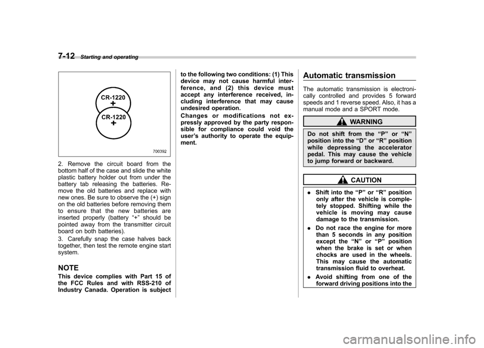
2. Remove the circuit board from the
bottom half of the case and slide the white
plastic battery holder out from under the
battery tab releasing the batteries. Re-
move the old batteries and replace with
new ones. Be sure to observe the (+) sign
on the old batteries before removing them
to ensure that the new batteries are
inserted properly (battery “+ ” should be
pointed away from the transmitter circuit
board on both batteries).
3. Carefully snap the case halves back
together, then test the remote engine startsystem.
NOTE
This device complies with Part 15 of
the FCC Rules and with RSS-210 of
Industry Canada. Operation is subject to the following two conditions: (1) This
device may not cause harmful inter-
ference, and (2) this device must
accept any interference received, in-
cluding interference that may cause
undesired operation.
Changes or modifications not ex-
pressly approved by the party respon-
sible for compliance could void theuser
’s authority to operate the equip-
ment. Automatic transmission
The automatic transmission is electroni-
cally controlled and provides 5 forward
speeds and 1 reverse speed. Also, it has a
manual mode and a SPORT mode.
WARNING
Do not shift from the “P ” or “N ”
position into the “D ” or “R ” position
while depressing the accelerator
pedal. This may cause the vehicle
to jump forward or backward.
CAUTION
. Shift into the “P ” or “R ” position
only after the vehicle is comple-
tely stopped. Shifting while the
vehicle is moving may cause
damage to the transmission.
. Do not race the engine for more
than 5 seconds in any position
except the “N ” or “P ” position
when the brake is set or when
chocks are used in the wheels.
This may cause the automatic
transmission fluid to overheat.
. Avoid shifting from one of the
forward driving positions into the
Page 256 of 422
“R ” position or vice versa until
the vehicle has completely
stopped. Such shifting may
cause damage to the transmis-sion.
. When parking the vehicle, first
securely apply the parking brake
and then place the select lever inthe “P ” position. Avoid parking
for a long time with the select
lever in any other position as
doing so could result in a dead
battery.
NOTE . When the engine coolant tempera-
ture is still low, the automatic transmis-
sion will upshift to higher engine
speeds than when the coolant tempera-
ture is sufficiently high in order to
shorten the warm-up time and improve
driveability. The gearshift timing will
automatically shift to the normal timing
after the engine has warmed up.. Immediately after ATF (automatic
transmission fluid) is replaced, you
may feel that the automatic transmis-
sion operation is somewhat unusual.
This results from invalidation of data
which the on-board computer has
collected and stored in memory to allow the transmission to shift at the
most appropriate times for the current
condition of your vehicle. Optimized
shifting will be restored as the vehicle
continues to be driven for a while.
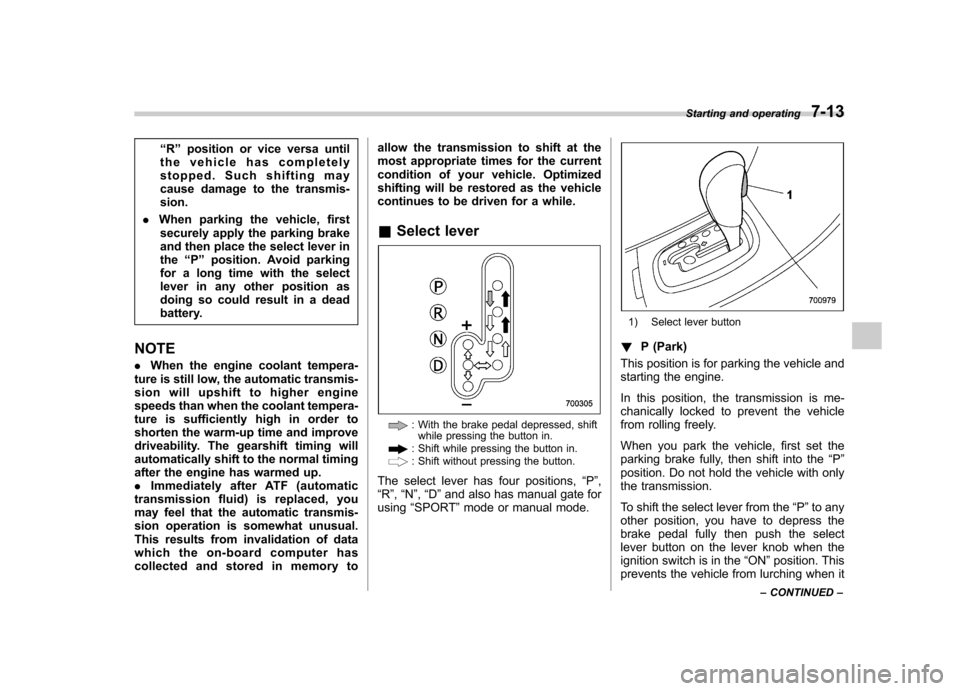
& Select lever
: With the brake pedal depressed, shift
while pressing the button in.
: Shift while pressing the button in.: Shift without pressing the button.
The select lever has four positions, “P ”,
“ R ”, “N ”, “D ”and also has manual gate for
using “SPORT ”mode or manual mode.
1) Select lever button
! P (Park)
This position is for parking the vehicle and
starting the engine.
In this position, the transmission is me-
chanically locked to prevent the vehicle
from rolling freely.
When you park the vehicle, first set the
parking brake fully, then shift into the “P ”
position. Do not hold the vehicle with only
the transmission.
To shift the select lever from the “P ”to any
other position, you have to depress the
brake pedal fully then push the select
lever button on the lever knob when the
ignition switch is in the “ON ”position. This
prevents the vehicle from lurching when it Starting and operating
7-13
– CONTINUED –
Page 257 of 422
7-14Starting and operating
is started.
If the select lever does not move from the “P ” position with the brake pedal de-
pressed, the select lever button pushed
in, and the ignition switch in the ON
position, refer to “Shift lock function ”F 7-
14. ! R (Reverse)
This position is for backing the vehicle.
To shift from the “N ” to “R ”position, stop
the vehicle completely then move the
lever to the “R ” position while pushing
the select lever button. ! N (Neutral)
This position is for restarting a stalled engine.
In this position the wheels and transmis-
sion are not locked. In this position, the
transmission is neutral; the vehicle will roll
freely, even on the slightest incline unless
the parking brake or foot brake is applied.
Avoid coasting with the transmission neutral.
During coasting, there is no engine brak-
ing effect.
NOTE
When the ignition switch has been
turned to the “LOCK ”position, move-
ment of the select lever from the “N ” position to the
“R ” position is possible
for a limited time period by depressing
the brake pedal and then becomes
impossible. If the select lever becomes
impossible to be moved after a limited
time period, turn the ignition switch tothe “ON ”position. You will then be able
to move the select lever to the “P ”
position.
WARNING
Do not drive the vehicle with the
select lever in the “N ” (Neutral)
position. Engine braking has no
effect in this condition and the risk
of an accident is consequently in-creased.
! D (Drive)
This position is for normal driving.
The transmission automatically shifts into
a suitable gear from 1st to 5th according to
the vehicle speed and the acceleration
you require.
When more acceleration is required in this
position, depress the accelerator pedal
fully to the floor and hold that position. The
transmission will automatically downshift
to 4th, 3rd, 2nd or 1st gear. When you
release the pedal, the transmission will return to the original gear position.
To use the SPORT mode, move the lever
from this position into the manual gate.
To use the manual mode, move the lever
from this position into the manual gate
then move it toward the
“+ ” and “� ” ends.
! While climbing a grade
When driving up a hill, undesired upshift to
4th or 5th gear is prevented from taking
place when the accelerator is released.
This minimizes the chance of subsequent
downshifting to a lower gear when accel-
erating again. This prevents repeated
upshifting and downshifting resulting in a
smoother operation of the vehicle.
NOTE
The transmission may downshift to 2nd
or 1st gear, depending on the way the
accelerator pedal is depressed to ac-
celerate the vehicle again. & Shift lock function
The shift lock function helps prevent the
improper operation of the select lever. . The select lever cannot be operated
unless the ignition switch is turned to the “ ON ”position and the brake pedal is
depressed. . The select lever cannot be moved from