wheel size SUBARU TRIBECA 2014 1.G User Guide
[x] Cancel search | Manufacturer: SUBARU, Model Year: 2014, Model line: TRIBECA, Model: SUBARU TRIBECA 2014 1.GPages: 426, PDF Size: 6.37 MB
Page 311 of 426
9-4In case of emergency
and pull it through the center of thetemporary spare tire.
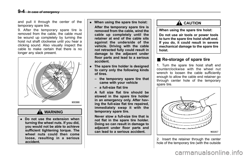
9. After the temporary spare tire isremoved from the cable, the cable mustbe wound up completely by turning thehoist nut shaft clockwise until you hear aclicking sound. Also visually inspect thecable to make certain that there is nolonger any slack present.
WARNING
.Do not use the extension whenturning the wheel nuts. If you did,you would not be able to achievesufficient tightening torque. Thewheel nuts could then comeloose, resulting in a seriousaccident.
.When using the spare tire hoist:
After the temporary spare tire isremoved from the cable, wind thecable up completely until theretainer at end of the cable sitsagainst the underside of thevehicle. Driving with the cablenot retracted fully could result indamage to the adjacent underfloor partsand lead to a seriousaccident.
.The spare tire holder is designedto carry only the following kindsof tires.
–the temporaryspare tire thatcame with your vehicle
–a full-size flat tire
A full size flat tire should bestowed in the spare tire holderin an emergency only. After hav-ing the full-sizeflat tire repaired,immediately swap it with thetemporary spare tire.
Never stow a full-size tire that isnot flat in the spare tire holder.Doing so can result in damage toadjacent under floor parts andcan lead to a serious accident.
CAUTION
When using the spare tire hoist:
Do not use air tools or power toolsto turn the spare tire hoist shaft end.If you do, it could result in severemechanical damage to the spare tirehoist.
&Re-storage of spare tire
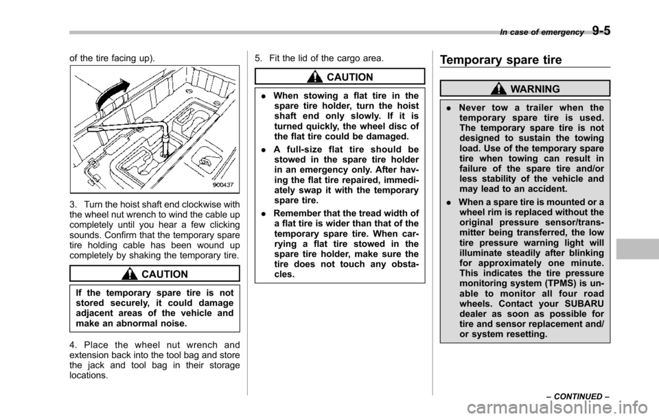
1. Turn the spare tire hoist shaft endcounterclockwise with the wheel nutwrench to loosen the cable sufficientlyenough to allow the cable end retainer gothrough center hole of the temporaryspare tire.
2. Insert the retainer through the centerhole of the temporary tire (with the outside
Page 312 of 426
of the tire facing up).
3. Turn the hoist shaft end clockwise withthe wheel nut wrench to wind the cable upcompletely until you hear a few clickingsounds.Confirm that the temporary sparetire holding cable has been wound upcompletely by shaking the temporary tire.
CAUTION
If the temporary spare tire is notstored securely, it could damageadjacent areas of the vehicle andmake an abnormal noise.
4. Place the wheel nut wrench andextension back into the tool bag and storethe jackand tool bag in their storagelocations.
5. Fit the lid of the cargo area.
CAUTION
.When stowing a flat tire in thespare tire holder, turn the hoistshaft end only slowly. If it isturned quickly, the wheel disc ofthe flat tire could be damaged.
.Afull-sizeflattireshouldbestowed in the spare tire holderin an emergency only. After hav-ingthe flat tire repaired, immedi-ately swap it with the temporaryspare tire.
.Remember that the tread width ofa flat tire is wider than that of thetemporary spare tire. When car-rying a flat tire stowed in thespare tire holder, make sure thetiredoes not touch any obsta-cles.
Temporary spare tire
WARNING
.Never tow a trailer when thetemporary spare tire is used.The temporary spare tire is notdesigned to sustain the towingload. Use of the temporary sparetire when towing can result infailure of the spare tire and/orless stability of the vehicle andmay lead to an accident.
.When a spare tire is mounted or awheel rim is replaced without theoriginal pressure sensor/trans-mitter being transferred, the lowtire pressure warning light willilluminate steadily after blinkingfor approximately one minute.This indicates the tire pressuremonitoring system (TPMS) is un-able to monitor all four roadwheels. Contact your SUBARUdealer as soon as possible fortire and sensor replacement and/or system resetting.
In case of emergency9-5
–CONTINUED–
Page 313 of 426
9-6In case of emergency
CAUTION
Never use any temporary spare tireother than the original. Using othersizes may result in severe mechan-ical damage to the drive train of yourvehicle.
The temporary spare tire is smaller andlighter than a conventional tire and isdesigned for emergency use only. Re-move thetemporary spare tire and re-install the conventional tire as soon aspossible because the spare tire is de-signed only for temporary use.
Check the inflation pressure of the tem-porary spare tire periodically to keep thetire ready for use. The correct pressure is60 psi (420 kPa, 4.2 kgf/cm2).
When using the temporary spare tire, notethe following.
.Do not exceed 50 mph (80 km/h).
.Do not put a tire chain on the temporaryspare tire.Because of the smaller tire size,a tire chain will not fit properly.
.Do not use two or more temporaryspare tires at the same time.
.Do not drive over obstacles. This tirehas a smaller diameter, so road clearanceis reduced.
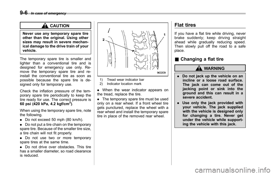
1) Tread wear indicator bar2) Indicator location mark
.When the wear indicator appears onthe tread, replace the tire.
.The temporary spare tire must be usedonly on a rear wheel. If a front wheel tiregets punctured, replace the wheel with arear wheel and install the temporary sparetire in place of the removed rear wheel.
Flat tires
If you have a flat tire while driving, neverbrake suddenly; keep driving straightahead while gradually reducing speed.Then slowly pull off the road to a safeplace.
&Changing a flat tire
WARNING
.Do not jack up the vehicle on anincline or a loose road surface.The jack can come out of thejacking point or sink into theground and this can result in asevere accident.
.Use only the jack provided withyour vehicle. The jack suppliedwith the vehicle is designed onlyfor changing a tire. Never getunder the vehicle while support-ing the vehicle with this jack.
Page 317 of 426
9-10In case of emergency
holder.
Refer to“Spare tire”F9-2 for its location,instructions and precautions.
CAUTION
.When stowing a flat tire in thespare tire holder, turn the hoistshaft end only slowly. If it isturned quickly, the wheel disc ofthe flat tire could be damaged.
.Afull-sizeflattireshouldbestowed in the spare tire holderin an emergency only. After hav-ing the flat tire repaired, immedi-ately swap it with the temporaryspare tire.
.Remember that the tread width ofa flat tire is wider than that of thetemporary spare tire. When car-rying a flat tire stowed in thespare tire holder, make sure thetire does not touch any obsta-cles.
WARNING
Never place a tire or tire changingtools in the passenger compartmentafter changing wheels. In a suddenstop or collisions, loose equipment
could strike occupants and causeinjury. Store the tire and all tools inthe proper place.
&Tire pressure monitoring
system (TPMS)
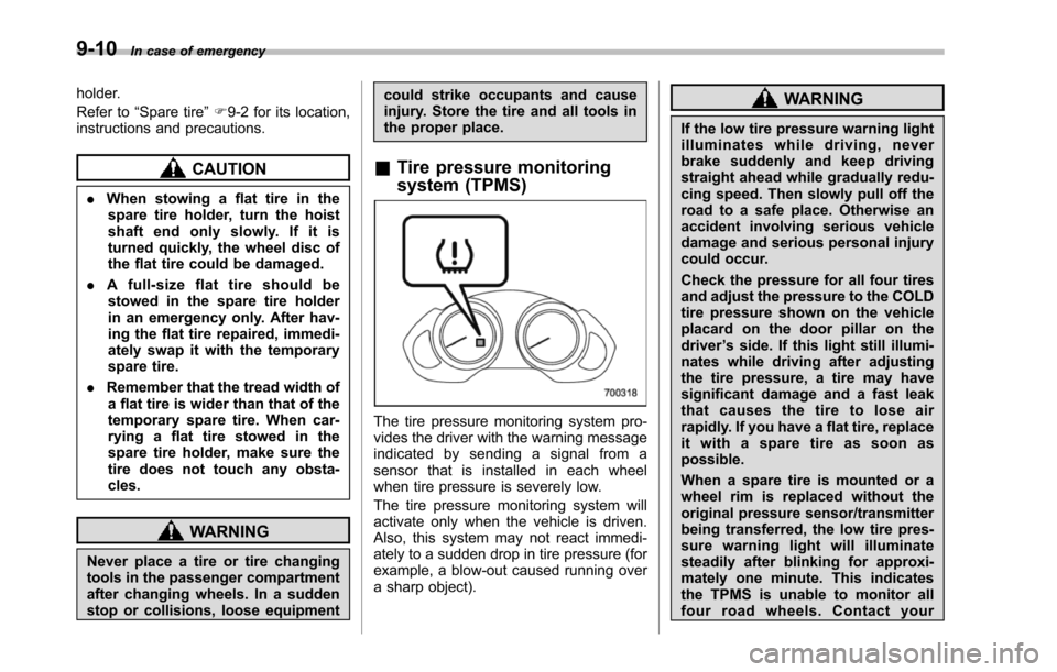
The tire pressure monitoring system pro-vides the driver with the warning messageindicated by sending a signal from asensor that is installed in each wheelwhen tire pressure is severely low.
The tire pressure monitoring system willactivate only when the vehicle is driven.Also, this system may not react immedi-ately to a sudden drop in tire pressure (forexample, a blow-out caused running overa sharp object).
WARNING
If the low tire pressure warning lightilluminates while driving, neverbrake suddenly and keep drivingstraight ahead while gradually redu-cing speed. Then slowly pull off theroad to a safe place. Otherwise anaccident involving serious vehicledamageand serious personal injurycould occur.
Check the pressure for all four tiresand adjust the pressure to the COLDtire pressure shown on the vehicleplacard on the door pillar on thedriver’s side. If this light still illumi-nates while driving after adjustingthe tire pressure, a tire may havesignificant damage and a fast leakthat causes the tire to lose airrapidly. If you have a flat tire, replaceit with a spare tire as soon aspossible.
When a spare tire is mounted or awheel rim is replaced without theoriginal pressure sensor/transmitterbeing transferred, the low tire pres-sure warning light will illuminatesteadily afterblinking for approxi-mately one minute. This indicatesthe TPMS is unable to monitor allfour road wheels. Contact your
Page 330 of 426
nents.
!Using a warm water washer
.Keep a good distance of 12 in (30 cm)or more between the washer nozzle andthe vehicle.
.Do not wash the same area continu-ously.
.If a stain will not come out easily, washby hand. Some warm water washers areof the high temperature, high pressuretype, and they can damage or deform theresin parts such as mouldings, or causewater to leak into the vehicle.
&Waxing and polishing
Always wash and dry the vehicle beforewaxing and polishing.
Use a good quality polish and wax andapply them according to the manufac-turer’s instructions. Wax or polish whenthe painted surface is cool.
Be sure to polish and wax the chrome trim,as well as the painted surfaces. Loss ofwax on a painted surface leads to loss ofthe original luster and also quickens thedeterioration of the surface. It is recom-mended that a coat of wax be applied atleast once a month, or whenever thesurface no longer repels water.
If the appearance of the paint has dimin-
ished to the point where the luster or tonecannot be restored, lightly polish thesurface with a fine-grained compound.Never polish just the affected area, butinclude the surrounding area as well.Always polish in only one direction. ANo. 2000 grain compound is recom-mended. Never use a coarse-grainedcompound. Coarser grained compoundshave a smaller grain-size number andcould damage the paint. After polishingwith a compound, coat with wax to restorethe original luster. Frequent polishing withacompoundoranincorrectpolishingtechnique will result in removing the paintlayer and exposing the undercoat. Whenin doubt, it is always best to contact yourSUBARU dealer or an auto paint specia-list.
CAUTION
Do not use any agents with organicsolventson the surface of the bulbassembly cover. However, if a polishor wax with organic solvents isapplied to the cover surface, com-pletely wipe off the polish or wax.Otherwise, the cover surface may bedamaged.
NOTE
Be careful not to block the windshieldwasher nozzles with wax when waxingthe vehicle.
&Cleaning aluminum wheels
.Promptly wipethe aluminum wheelsclean of any kind of grime or agent. If dirtis left on too long, it may be difficult toclean off.
.Do not use soap containing grit toclean the wheels. Be sure to use a neutralcleaning agent, and later rinse thoroughlywith water. Do not clean the wheels with astiff brush or expose them to a high-speedwashing device.
.Clean the vehicle (including the alumi-num wheels) with water as soon aspossible when it has been splashed withsea water, exposed to sea breezes, ordriven on roads treated with salt or otheragents.
Appearance care10-3
Page 359 of 426

11-26Maintenance and service
the direction mark facing forward.
&Tire rotation
Vehicles equipped with 4 non-unidirec-tional tires1) Front
Vehicles equipped with unidirectional tires1) Front
Tire wear varies from wheel to wheel. Tomaximize the life of each tire and ensurethat the tires wear uniformly, it is best torotate the tires every 7,500 miles (12,000km). Move the tires to the positions shownin the illustration each time they arerotated.
Replace any damaged or unevenly worntire at the time of rotation. After tirerotation, adjust the tire pressures andmake sure the wheel nuts are correctlytightened.
After driving approximately 600 miles(1,000 km), check the wheel nuts againand retighten any nut that has becomeloose.
&Tire replacement
The wheels and tires are important andintegral parts of your vehicle’s design;they cannot be changed arbitrarily. Thetires fitted as standard equipment areoptimally matched to the characteristicsof the vehicle and were selected to givethe best possible combination of runningperformance, ride comfort, and servicelife. It is essential for every tire to have asize and construction matching thoseshown on the tire placard and to have aspeed symbol and load index matchingthose shown on the tire placard.
Usingtires of a non-specified size detractsfrom controllability, ride comfort, brakingperformance, speedometer accuracy andodometer accuracy. It also creates incor-rect body-to-tire clearances and inappro-priately changes the vehicle’sgroundclearance.
All four tires must be the same in terms ofmanufacturer, brand (tread pattern), con-struction, and size. You are advised toreplace the tires with new ones that areidentical to those fitted as standard equip-ment.
For safe vehicle operation, SUBARUrecommends replacing all four tires atthe same time.
Page 360 of 426
WARNING
.When replacing a tire, you mustuse a tire that is of the same size,circumference, speed symboland load index as the originaltires listed on the tire placard.Using tires of other sizes, cir-cumferences or constructionsmay result in severe mechanicaldamage to the drive train of yourvehicle and may affect ride,handling, braking, speedometer/odometer calibration, and clear-ance betweenthe body and tires.It also may be dangerous andlead to loss of vehicle control.
.You must install four tires that areof the same size, circumference,construction, manufacturer,brand(tread pattern), degree ofwear, speed symbol and loadindex. Mixing tires of differenttypes, sizes or degrees of wearcan result in damage to thevehicle’spowertrain.Useofdifferent types or sizes of tirescan also dangerously reducecontrollability and braking per-formance and can lead to anaccident.
.Use only radial tires. Do not use
radial tires together with beltedbias tires and/or bias-ply tires.Doing so can dangerously re-duce controllability, resulting inan accident.
&Wheel replacement
When replacing wheels due, for example,to damage, make sure the replacementwheels match the specifications of thewheels that are fitted as standard equip-ment. Replacement wheels are availablefrom SUBARUdealers.
WARNING
Use only those wheels that arespecified for your vehicle. Wheelsnot meeting specifications couldinterfere with brake caliper opera-tion and may cause the tires to rubagainst the wheel well housing dur-ing turns. The resulting loss ofvehicle control could lead to anaccident.
Aluminum wheels
.Aluminum wheels can be scratchedand damaged easily. Handle them care-fully to maintain their appearance, perfor-mance, and safety.
.When any of the wheels are removedand replaced for tire rotation or to changea flat tire, always check the tightness ofthe wheel nuts after driving approximately600 miles (1,000 km). If any nut is loose,tighten it to the specified torque.–For the wheel nut tightening torque,refer to“Tires”F12-8.–For the wheel nut tightening proce-dure, refer to“Changing a flat tire”F9-6..Never apply oil to the threaded parts,wheel nuts, or tapered surface of thewheel.
.Never let the wheel rub against sharpprotrusions or curbs.
.When wheel nuts, balance weights, orthe center cap is replaced, be sure toreplace them with genuine SUBARU partsdesigned for the specific wheel.
Maintenance and service11-27
Page 385 of 426

12-8Specifications
&Tires
Tire sizeP255/55R18 104H 255/55R18 105H
Wheel size1868JJ
Pressure Front33 psi (230 kPa, 2.3 kgf/cm2)
Rear 32 psi (220 kPa, 2.2 kgf/cm2)
Temporary spare tireSize T165/80R17
Pressure 60 psi (420 kPa, 4.2 kgf/cm2)
Wheel nut tightening torqueAluminum wheels (silver-colored) 89 lbf·ft (120 N·m, 12 kgf·m)*1*3
Chrome-finished wheels 111 lbf·ft (150 N·m, 15 kgf·m)*2*3
Temporary spare tire wheel89 lbf·ft (120 N·m, 12 kgf·m)*1*3
*1: This torque is equivalent to applying the following load at the end of the wheel nut wrench.When you use a wheel nut wrench of the10.8-inch (275 mm)length: Approximately 96 to 115 lbf (43 to 52 kgf)When you use a wheel nut wrench of the13.2-inch (335 mm)length: Approximately 73 to 87 lbf (33 to 40 kgf)If you have tightened the wheel nuts by yourself, have the tightening torque checked at the nearest automotive service facility as soon as possible.
*2: This torque is equivalent to applying approximately 87 to 109 lbf (40 to 49 kgf) at the end of the wheel nut wrench with a length of13.2 inches (335mm). If you have tightened the wheel nuts by yourself, have the tightening torque checked at the nearest automotive service facility as soon as possible.
*3: For informationabout the length of the wheelnut wrenchand the wheel nut tightening procedure, refer to“Changinga flat tire”F9-6.
Page 400 of 426
.Measuring rim
The rim on which a tire is fitted for
physical dimension requirements.
.Normal occupant weight
150 lbs (68 kg) times the number of
occupants specified in the second
column of Table 1 that is appended
to the end of this section.
.Occupant distribution
Distribution of occupants in a vehi-
cle as specified in the third column
of Table 1 that is appended to the
end of this section.
.Open splice
Any parting at any junction of tread,
sidewall, or innerliner that extends
to cord material.
.Outer diameter
The overall diameter of an inflated
new tire.
.Overall width
The linear distance between the
exteriors of the sidewalls of an
inflated tire, including elevations
due to labeling, decorations, or
protective bands or ribs.
.Passenger car tire
A tire intended for use on passen-
ger cars, multipurpose passenger
vehicles, and trucks, that have a
gross vehicle weight rating (GVWR)
of 10,000 lbs (4,535 kg) or less.
.Ply
A layer of rubber-coated parallel
cords.
.Ply separation
Apartingofrubbercompound
between adjacent plies.
.Pneumatic tire
A mechanical device made of rub-
ber, chemicals, fabric and steel or
other materials, that, when
mounted on an automotive wheel,
provides the traction and contains
the gas or fluid that sustains the
load.
.Production options weight
The combined weight of those
installed regular production options
weighing over 5.1 lbs (2.3 kg) in
excess of those standard items
which they replace, not previously
considered in curb weight or acces-
sory weight, including heavy duty
brakes, ride levelers, roof rack,
heavy duty battery, and special
trim.
.Radial ply tire
A pneumatic tire in which the ply
cords that extend to the beads are
laid at substantially 90 degrees to
the centerline of the tread.
.Recommended inflation pres-
sure
The cold inflation pressure recom-
mended by a vehicle manufacturer.
.Reinforced tire
A tire designed to operate at higher
loads and at higher inflation pres-
sures than the corresponding stan-
dard tire.
.Rim
A metal support for a tire or a tire
and tube assembly upon which the
tire beads are seated.
.Rim diameter
Nominal diameter of the bead seat.
.Rim size designation
Rim diameter and width.
Consumer information and Reporting safety defects13-7
–CONTINUED–
Page 419 of 426

14-10Index
Tire . . . . . . . . . . . . . . . . . . . . . . . . . . . . . . . . . . . . . . . . . . . . . . . . . . . . . . . . . . . . . . . . . 11-21, 12-8Chains.................................................................. 8-11Inspection............................................................ 11-22Pressures and wear.............................................. 11-23Replacement........................................................ 11-26Rotation............................................................... 11-26Size and pressure.................................................. 12-8Types.................................................................. 11-21Tire pressure monitoring system (TPMS)..... 7-27, 9-10, 11-21Warning light......................................................... 3-14Tires and wheels....................................................... 11-21Tools........................................................................ 9-19Top tether anchorages........................................ 1-37, 1-40Towing...................................................................... 9-14All wheels on the ground........................................ 9-17Flat-bed truck........................................................ 9-17Hooks................................................................... 9-15Weight ..................................................................8-21Traction Control systemOFF indicator light.................................................. 3-19OFF switch........................................................... 7-25TrailerConnecting............................................................ 8-19Hitch............................................................ 8-18, 8-24Towing.................................................................. 8-21Towing tips............................................................ 8-26Trip meter................................................................... 3-7Turn signalIndicator lights....................................................... 3-21Lever.................................................................... 3-29
UUnder-floor storage compartment.................................. 6-16
VValet mode................................................................ 2-18Vanity mirror...................................................... 6-5, 11-43VehicleCapacity weight...................................................... 8-12Identification........................................................ 12-15Symbols.................................................................... 3Vehicle Dynamics ControlOperation indicator light................................... 3-18, 3-19System.................................................................. 7-23Warning light.................................................. 3-18, 3-19Ventilator.................................................................... 4-2
WWarning and indicator lights.......................................... 3-9Warning chimesSeatbelt................................................................. 3-10Warning lightABS .............................................................. 3-15, 7-21All-Wheel Drive...................................................... 3-18AT OIL TEMP......................................................... 3-13Brake system......................................................... 3-16Charge.................................................................. 3-13CHECK ENGINE.................................................... 3-12Door open............................................................. 3-17Low fuel................................................................ 3-17Low tire pressure.................................................... 3-14Oil pressure........................................................... 3-13