turn signal SUZUKI AERIO 2007 1.G Owners Manual
[x] Cancel search | Manufacturer: SUZUKI, Model Year: 2007, Model line: AERIO, Model: SUZUKI AERIO 2007 1.GPages: 232, PDF Size: 3.34 MB
Page 16 of 232
Downloaded from www.Manualslib.com manuals search engine 2-3 BEFORE DRIVING
54G27-03E
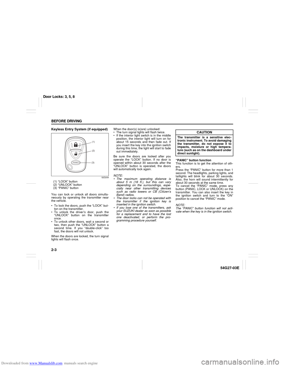
Keyless Entry System (if equipped)
52D209
(1) “LOCK” button
(2) “UNLOCK” button
(3) “PANIC” button
You can lock or unlock all doors simulta-
neously by operating the transmitter near
the vehicle.
To lock the doors, push the “LOCK” but-
ton on the transmitter.
To unlock the driver’s door, push the
“UNLOCK” button on the transmitter
once.
To unlock other doors, wait a second or
two, then push the “UNLOCK” button a
second time. If you “double-click” too
fast, the doors will not unlock.
When the doors are locked, the turn signal
lights will flash once.When the door(s) is(are) unlocked:
The turn signal lights will flash twice.
If the interior light switch is in the middle
position, the interior light will turn on for
about 15 seconds and then fade out. If
you insert the key into the ignition switch
during this time, the light will start to fade
out immediately.
Be sure the doors are locked after you
operate the “LOCK” button. If no door is
opened within about 30 seconds after the
“UNLOCK” button is operated, the doors
will automatically lock again.
NOTE:
The maximum operating distance is
about 5 m (16 ft.), but this can vary
depending on the surroundings, espe-
cially near other transmitting devices
such as radio towers or CB (Citizen’s
Band) radios.
The door locks can not be operated with
the transmitter if the ignition key is
inserted in the ignition switch.
If you lose one of the transmitters, ask
your SUZUKI dealer as soon as possible
for a replacement and to have the lost
one deactivated, or perform the pro-
gramming procedure yourself.“PANIC” button function
This function is to get the attention of oth-
ers.
Press the “PANIC” button for more than 1
second. The headlights, parking lights, and
taillights will blink for about 30 seconds.
Also, the horn will sound intermittently for
about 30 seconds at the same time.
To cancel the “PANIC” mode, press any
button (PANIC, LOCK or UNLOCK) on the
transmitter. You can also insert the key in
the ignition switch and turn to the “ON”
position to cancel the “PANIC” mode.
NOTE:
The “PANIC” button function will not acti-
vate when the key is in the ignition switch.
(1)
(2)
(3)
CAUTION
The transmitter is a sensitive elec-
tronic instrument. To avoid damaging
the transmitter, do not expose it to
impacts, moisture or high tempera-
ture (such as on the dashboard under
direct sunlight).
Door Locks: 3, 5, 8
Page 55 of 232
Downloaded from www.Manualslib.com manuals search engine STEERING COLUMN CONTROLS
3
54G27-03E
60G405
STEERING COLUMN CONTROLSIgnition Switch ..................................................................... 3-1
Lighting/Turn Signal Control Lever ................................... 3-3
Windshield Wiper and Washer Lever ................................ 3-4
Rear Window Wiper/Washer Switch (if equipped) ........... 3-5
Tilt Steering Lock Lever ..................................................... 3-6
Cruise Control (if equipped) ............................................... 3-6
Remote Audio Controls (if equipped) ............................... 3-8
Horn ...................................................................................... 3-8
Page 58 of 232
Downloaded from www.Manualslib.com manuals search engine 3-3 STEERING COLUMN CONTROLS
54G27-03E
Lighting/Turn Signal Control
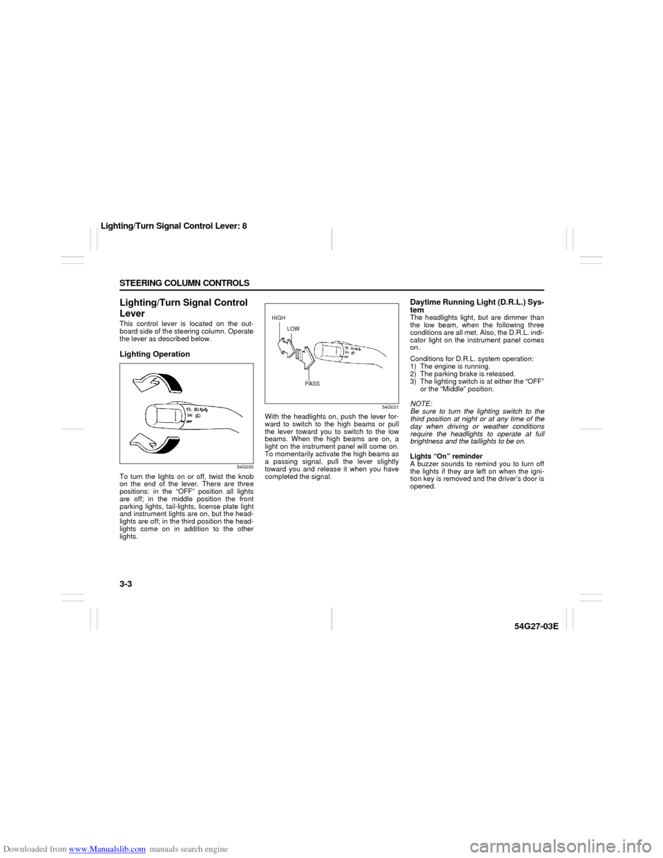
LeverThis control lever is located on the out-
board side of the steering column. Operate
the lever as described below.Lighting Operation
54G030
To turn the lights on or off, twist the knob
on the end of the lever. There are three
positions: in the “OFF” position all lights
are off; in the middle position the front
parking lights, tail-lights, license plate light
and instrument lights are on, but the head-
lights are off; in the third position the head-
lights come on in addition to the other
lights.
54G031
With the headlights on, push the lever for-
ward to switch to the high beams or pull
the lever toward you to switch to the low
beams. When the high beams are on, a
light on the instrument panel will come on.
To momentarily activate the high beams as
a passing signal, pull the lever slightly
toward you and release it when you have
completed the signal.
Daytime Running Light (D.R.L.) Sys-
temThe headlights light, but are dimmer than
the low beam, when the following three
conditions are all met. Also, the D.R.L. indi-
cator light on the instrument panel comes
on.
Conditions for D.R.L. system operation:
1) The engine is running.
2) The parking brake is released.
3) The lighting switch is at either the “OFF”
or the “Middle” position.
NOTE:
Be sure to turn the lighting switch to the
third position at night or at any time of the
day when driving or weather conditions
require the headlights to operate at full
brightness and the taillights to be on.
Lights “On” reminder
A buzzer sounds to remind you to turn off
the lights if they are left on when the igni-
tion key is removed and the driver’s door is
opened.
HIGH
LOW
PASS
Lighting/Turn Signal Control Lever: 8
Page 59 of 232
Downloaded from www.Manualslib.com manuals search engine 3-4 STEERING COLUMN CONTROLS
54G27-03E
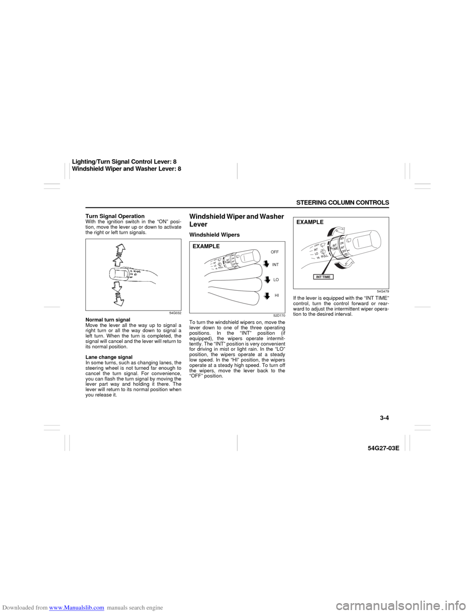
Turn Signal OperationWith the ignition switch in the “ON” posi-
tion, move the lever up or down to activate
the right or left turn signals.
54G032
Normal turn signal
Move the lever all the way up to signal a
right turn or all the way down to signal a
left turn. When the turn is completed, the
signal will cancel and the lever will return to
its normal position.
Lane change signal
In some turns, such as changing lanes, the
steering wheel is not turned far enough to
cancel the turn signal. For convenience,
you can flash the turn signal by moving the
lever part way and holding it there. The
lever will return to its normal position when
you release it.
Windshield Wiper and Washer
LeverWindshield Wipers
52D170
To turn the windshield wipers on, move the
lever down to one of the three operating
positions. In the “INT” position (if
equipped), the wipers operate intermit-
tently. The “INT” position is very convenient
for driving in mist or light rain. In the “LO”
position, the wipers operate at a steady
low speed. In the “HI” position, the wipers
operate at a steady high speed. To turn off
the wipers, move the lever back to the
“OFF” position.
54G479
If the lever is equipped with the “INT TIME”
control, turn the control forward or rear-
ward to adjust the intermittent wiper opera-
tion to the desired interval.
INT
LO
HI OFF
EXAMPLE
EXAMPLE
Lighting/Turn Signal Control Lever: 8
Windshield Wiper and Washer Lever: 8
Page 66 of 232
Downloaded from www.Manualslib.com manuals search engine 4-1 INSTRUMENT PANEL
54G27-03E
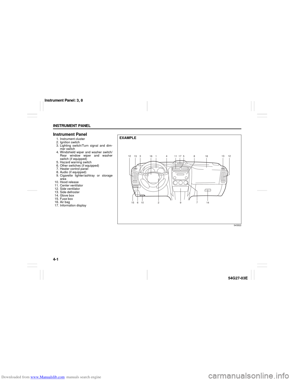
Instrument Panel1. Instrument cluster
2. Ignition switch
3. Lighting switch/Turn signal and dim-
mer switch
4. Windshield wiper and washer switch/
Rear window wiper and washer
switch (if equipped)
5. Hazard warning switch
6. Other switches (if equipped)
7. Heater control panel
8. Audio (if equipped)
9. Cigarette lighter/ashtray or storage
area
10. Hood release
11. Center ventilator
12. Side ventilator
13. Side defroster
14. Glove box
15. Fuse box
16. Air bag
17. Information display
54G522
EXAMPLE
12
13316
14
11
175
8161312
14 7
9
2
10
6 15
Instrument Panel: 3, 8
Page 71 of 232
Downloaded from www.Manualslib.com manuals search engine 4-6 INSTRUMENT PANEL
54G27-03E
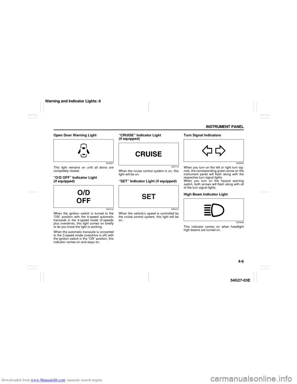
Open Door Warning Light
54G391
This light remains on until all doors are
completely closed.“O/D OFF” Indicator Light
(if equipped)
54G142
When the ignition switch is turned to the
“ON” position with the 4-speed automatic
transaxle in the 4-speed mode (3-speeds
plus overdrive), this light comes on briefly
to let you know the light is working.
When the automatic transaxle is converted
to the 3-speed mode (overdrive is off) with
the ignition switch in the “ON” position, this
indicator comes on and stays on.
“CRUISE” Indicator Light
(if equipped)
52D113
When the cruise control system is on, this
light will be on.“SET” Indicator Light (if equipped)
65D474
When the vehicle’s speed is controlled by
the cruise control system, this light will be
on.
Turn Signal Indicators
50G055
When you turn on the left or right turn sig-
nals, the corresponding green arrow on the
instrument panel will flash along with the
respective turn signal lights.
When you turn on the hazard warning
switch, both arrows will flash along with all
of the turn signal lights.High Beam Indicator Light
50G056
This indicator comes on when headlight
high beams are turned on.
Warning and Indicator Lights: 8
Page 75 of 232
Downloaded from www.Manualslib.com manuals search engine 4-10 INSTRUMENT PANEL
54G27-03E
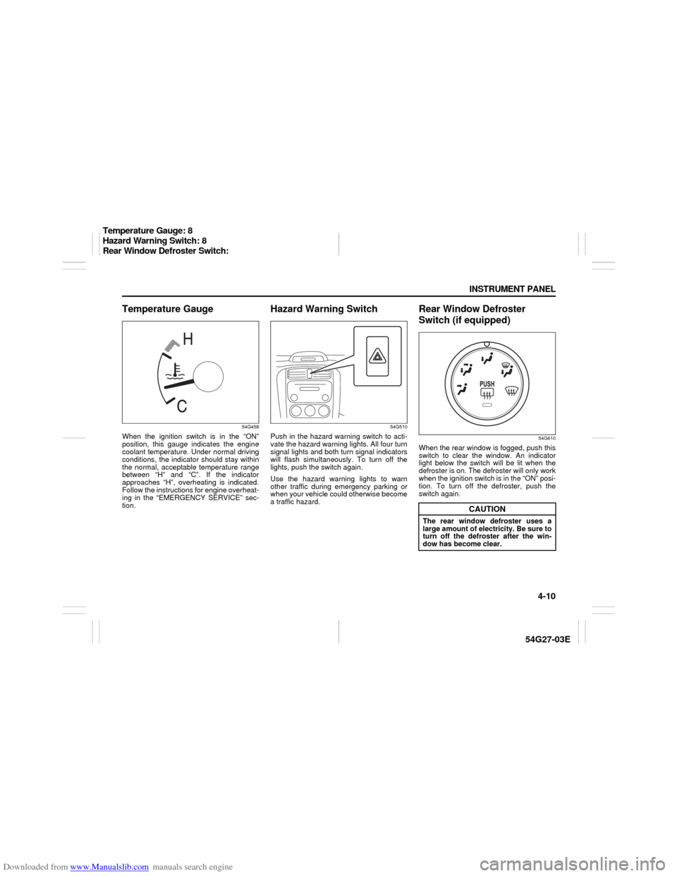
Temperature Gauge
54G458
When the ignition switch is in the “ON”
position, this gauge indicates the engine
coolant temperature. Under normal driving
conditions, the indicator should stay within
the normal, acceptable temperature range
between “H” and “C”. If the indicator
approaches “H”, overheating is indicated.
Follow the instructions for engine overheat-
ing in the “EMERGENCY SERVICE” sec-
tion.
Hazard Warning Switch
54G510
Push in the hazard warning switch to acti-
vate the hazard warning lights. All four turn
signal lights and both turn signal indicators
will flash simultaneously. To turn off the
lights, push the switch again.
Use the hazard warning lights to warn
other traffic during emergency parking or
when your vehicle could otherwise become
a traffic hazard.
Rear Window Defroster
Switch (if equipped)
54G610
When the rear window is fogged, push this
switch to clear the window. An indicator
light below the switch will be lit when the
defroster is on. The defroster will only work
when the ignition switch is in the “ON” posi-
tion. To turn off the defroster, push the
switch again.
CAUTION
The rear window defroster uses a
large amount of electricity. Be sure to
turn off the defroster after the win-
dow has become clear.
Temperature Gauge: 8
Hazard Warning Switch: 8
Rear Window Defroster Switch:
Page 97 of 232

Downloaded from www.Manualslib.com manuals search engine 4-32 INSTRUMENT PANEL
54G27-03E
Selecting the reception band
Press the band switch button (1).
Each time the button is pressed, the recep-
tion band is switched as follows:
54G550
Seek tuning
Press the seek up button (2) or the seek
down button (3).
The unit stops searching for a station at a
frequency where a broadcast station is
available.
Manual tuning
Turn the manual tuning knob (4).
The frequency being received is displayed.
Preset memory
1) Select the desired station.
2) Select the preset button (5) to which
you want to store the station and press
and hold the button for 2 seconds or
longer.
Auto store
1) Press the band switch button (1) and
select the band (FM2 or AM2).
2) Press the auto store button (6).Six stations in total are automatically
stored to the preset buttons (5) in sequen-
tial order, starting from the lower frequen-
cies.
NOTE:
When the auto store is performed, the
station previously stored in the memory
at the position is overwritten.
When there are fewer than 6 stations
that can be stored even if 2 rounds of
auto store operation are performed, the
stations previously stored at the remain-
ing preset buttons (5) are not overwrit-
ten.
Scan tuning
1) Press the scan button (7).
Stations are automatically sought for in
a sequential order, starting from a sta-
tion being currently received, and scan
stops for 5 seconds at a frequency
where there is a station available.
2) Press the scan button (7) again to stop
scanning at the frequency being cur-
rently received.
Receiving a stereo broadcast station
If a stereo broadcast station is received,
the stereo indicator (C) will light.
Radio Reception Radio reception can be affected by envi-
ronment, atmospheric conditions, or
radio signal’s power and distance from
the station. Nearby mountains and build-
ings may interfere or deflect radio recep-
tion, causing poor reception. Poor
reception or radio static can also be
caused by electric current from over-
head wires or high voltage power lines.
When listening to a radio while using a
cell phone or walkie-talkie in or close to
your vehicle, the radio may experience
noise interference.
Audio Systems:
Page 130 of 232
Downloaded from www.Manualslib.com manuals search engine 6-1 OPERATING YOUR VEHICLE
54G27-03E
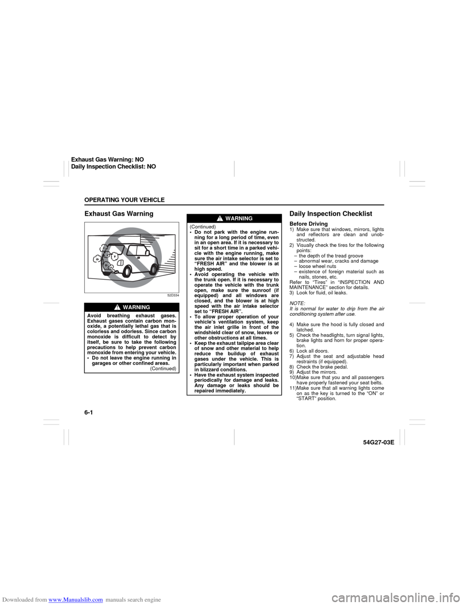
Exhaust Gas Warning
52D334
Daily Inspection ChecklistBefore Driving1) Make sure that windows, mirrors, lights
and reflectors are clean and unob-
structed.
2) Visually check the tires for the following
points:
– the depth of the tread groove
– abnormal wear, cracks and damage
– loose wheel nuts
– existence of foreign material such as
nails, stones, etc.
Refer to “Tires” in “INSPECTION AND
MAINTENANCE” section for details.
3) Look for fluid, oil leaks.
NOTE:
It is normal for water to drip from the air
conditioning system after use.
4) Make sure the hood is fully closed and
latched.
5) Check the headlights, turn signal lights,
brake lights and horn for proper opera-
tion.
6) Lock all doors.
7) Adjust the seat and adjustable head
restraints (if equipped).
8) Check the brake pedal.
9) Adjust the mirrors.
10)Make sure that you and all passengers
have properly fastened your seat belts.
11)Make sure that all warning lights come
on as the key is turned to the “ON” or
“START” position.
WARNING
Avoid breathing exhaust gases.
Exhaust gases contain carbon mon-
oxide, a potentially lethal gas that is
colorless and odorless. Since carbon
monoxide is difficult to detect by
itself, be sure to take the following
precautions to help prevent carbon
monoxide from entering your vehicle.
Do not leave the engine running in
garages or other confined areas.
(Continued)
WARNING
(Continued)
Do not park with the engine run-
ning for a long period of time, even
in an open area. If it is necessary to
sit for a short time in a parked vehi-
cle with the engine running, make
sure the air intake selector is set to
“FRESH AIR” and the blower is at
high speed.
Avoid operating the vehicle with
the trunk open. If it is necessary to
operate the vehicle with the trunk
open, make sure the sunroof (if
equipped) and all windows are
closed, and the blower is at high
speed with the air intake selector
set to “FRESH AIR”.
To allow proper operation of your
vehicle’s ventilation system, keep
the air inlet grille in front of the
windshield clear of snow, leaves or
other obstructions at all times.
Keep the exhaust tailpipe area clear
of snow and other material to help
reduce the buildup of exhaust
gases under the vehicle. This is
particularly important when parked
in blizzard conditions.
Have the exhaust system inspected
periodically for damage and leaks.
Any damage or leaks should be
repaired immediately.
Exhaust Gas Warning: NO
Daily Inspection Checklist: NO
Page 192 of 232
Downloaded from www.Manualslib.com manuals search engine 9-39 INSPECTION AND MAINTENANCE
54G27-03E
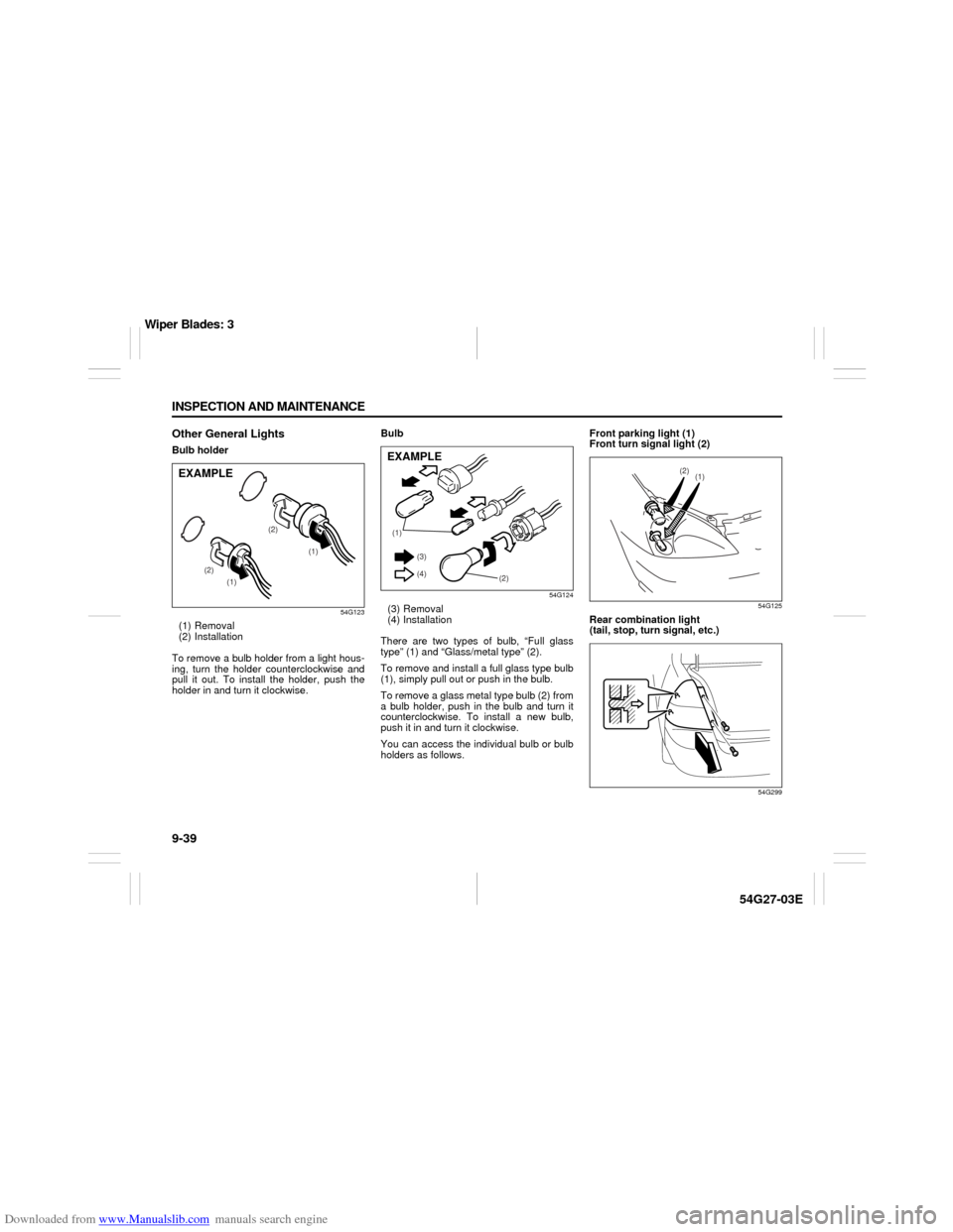
Other General LightsBulb holder
54G123
(1) Removal
(2) Installation
To remove a bulb holder from a light hous-
ing, turn the holder counterclockwise and
pull it out. To install the holder, push the
holder in and turn it clockwise.Bulb
54G124
(3) Removal
(4) Installation
There are two types of bulb, “Full glass
type” (1) and “Glass/metal type” (2).
To remove and install a full glass type bulb
(1), simply pull out or push in the bulb.
To remove a glass metal type bulb (2) from
a bulb holder, push in the bulb and turn it
counterclockwise. To install a new bulb,
push it in and turn it clockwise.
You can access the individual bulb or bulb
holders as follows.Front parking light (1)
Front turn signal light (2)
54G125
Rear combination light
(tail, stop, turn signal, etc.)
54G299
(1)
(1) (2)(2)
EXAMPLE
(1)
(2) (3)
(4)EXAMPLE
(1) (2)
Wiper Blades: 3