positive SUZUKI CELERIO 2015 Owners Manual
[x] Cancel search | Manufacturer: SUZUKI, Model Year: 2015, Model line: CELERIO, Model: SUZUKI CELERIO 2015Pages: 201, PDF Size: 5.82 MB
Page 20 of 201

0-8
76MH1-74E
55KS0-74E
10.All maintenance actions (as specified in the Owner’s Manualand Service Booklet) need to be followed and recorded in the manual for emission warranty.
11.The customer needs to produce the PUC (Pollution UnderControl) certificate valid for the period preceeding the testduring which the failure is discovered. The receipts (for themaintenance of the vehicle as per specification in Owner’sManual and Service Booklet from the date of original purchaseof the vehicle) will also be required.
Conditions under which the Emission Warranty is not APPLICABLE
1. In the absence of valid PUC certificate.
2. Vehicle not serviced from Maruti Suzuki authorised workshopas per the schedule specified in the Owner’s Manual.
3. Vehicle subjected to abnormal use (accident, motor race, ral-lies or for the purpose of establishing the records etc).
4. Use of non MGP (Maruti Geniune Part).
5. Vehicle tampered in an unauthorised manner.
6. Tampering with odometer so that the actual kilometer readingcan not be read.
7. Use of adulterated fuel and/or unspecified oils (Engine oil,Transmission oil and Brake oil etc).
Annexure - A
List of parts covered under Emission Warranty 1. Fuel Injection Assembly, Pressure Regulator, Throttle Body
Assembly.
2. Electronic Control Module (ECM).
3. Intake Manifold.
4. EGR valve.
5. Distributor and internal parts.
6. Ignition Coil.
7. Canister Assembly.
8. Vapour Liquid Seperator.
9. Fuel Tank and Filler Cap.
10. PCV (Positive Crankcase Ventilation) Valve.
11. Oil Filler Cap.
12. Catalytic Convertor.
13. Exhaust Manifold.
14. All Fuel Injection System related SENSORS.
15. High Pressure Fuel Pump.
16. Glow Plug.
17. Glow Plug Controller.
9
Page 150 of 201

7-1
INSPECTION AND MAINTENANCE
76MH1-74E
76MH1-74E
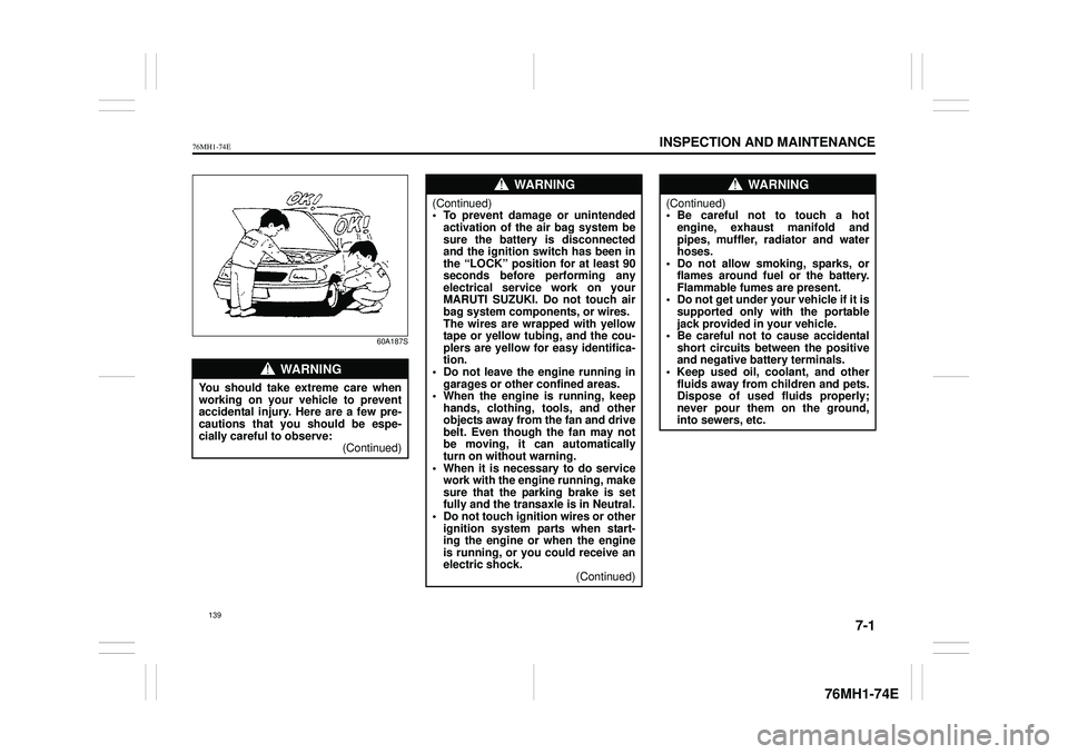
60A187S
WA R N I N G
You should take extreme care when working on your vehicle to preventaccidental injury. Here are a few pre- cautions that you should be espe- cially careful to observe:(Continued)
WA R N I N G
(Continued)• To prevent damage or unintendedactivation of the air bag system be sure the battery is disconnected and the ignition switch has been inthe “LOCK” position for at least 90 seconds before performing any electrical service work on yourMARUTI SUZUKI. Do not touch air bag system components, or wires. The wires are wrapped with yellowtape or yellow tubing, and the cou- plers are yellow for easy identifica- tion.• Do not leave the engine running in garages or other confined areas. • When the engine is running, keephands, clothing, tools, and other objects away from the fan and drive belt. Even though the fan may notbe moving, it can automatically turn on without warning. • When it is necessary to do servicework with the engine running, make sure that the parking brake is set fully and the transaxle is in Neutral.• Do not touch ignition wires or other ignition system parts when start- ing the engine or when the engineis running, or you could receive an electric shock. (Continued)
WA R N I N G
(Continued)• Be careful not to touch a hotengine, exhaust manifold and pipes, muffler, radiator and water hoses.• Do not allow smoking, sparks, or flames around fuel or the battery. Flammable fumes are present.• Do not get under your vehicle if it is supported only with the portable jack provided in your vehicle.• Be careful not to cause accidental short circuits be tween the positive and negative battery terminals.• Keep used oil, coolant, and other fluids away from children and pets. Dispose of used fluids properly;never pour them on the ground, into sewers, etc.
139
Page 169 of 201

7-20
INSPECTION AND MAINTENANCE
76MH1-74E
76MH1-74E
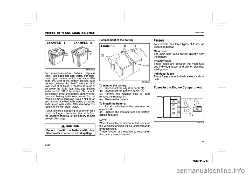
76MH0A136
For maintenance-free battery (cap-less type), you need not add water. For tradi-tional type battery, which has water filler caps, the level of the battery solution must be kept between the “MAX” and the “MIN”level lines at all times. If the level is found tobe below the “MIN” level line, add distilledwater to the “MAX” level line. You shouldperiodically check the battery, battery termi- nals, and battery hold-down bracket for cor- rosion. Remove corrosion using a stiff brushand ammonia mixed with water, or bakingsoda mixed with water. After removing cor-rosion, rinse with clean water.
If your vehicle is not going to be driven for amonth or longer, disconnect the cable fromthe negative terminal of the battery to help prevent discharge.
Replacement of the battery
51KM039
To remove the battery: (1) Disconnect the negative cable (1). (2) Disconnect the positive cable (2). (3) Remove the retainer nuts (3) andremove the retainer (4) (4) Remove the battery.
To install the battery: (1) Install the battery in the reverse order of removal. (2) Tighten the retainer nuts and battery cables securely.
NOTE: When the battery is disconnected, some of the vehicle’s function will be initialized and/or deactivated. These function are required to reset after the battery is reconnected.
Fuses
Your vehicle has three types of fuses, asdescribed below:
Main fuse The main fuse takes current directly fromthe battery.
Primary fuses These fuses are between the main fuse and individual fuses, and are for electrical load groups.
Individual fuses These fuses are for individual electrical cir-cuits.
Fuses in the Engine Compartment
68KH076
CAUTION
Do not overfill th e battery with dis- tilled water in order to avoid spillage.
EXAMPLE - 1 EXAMPLE - 2(1)
(2)
(3)
(4)
EXAMPLE
(1)
(2)
(3)
(27)
(28)
158
Page 186 of 201

8-5
EMERGENCY SERVICE
76MH1-74E
76MH1-74E
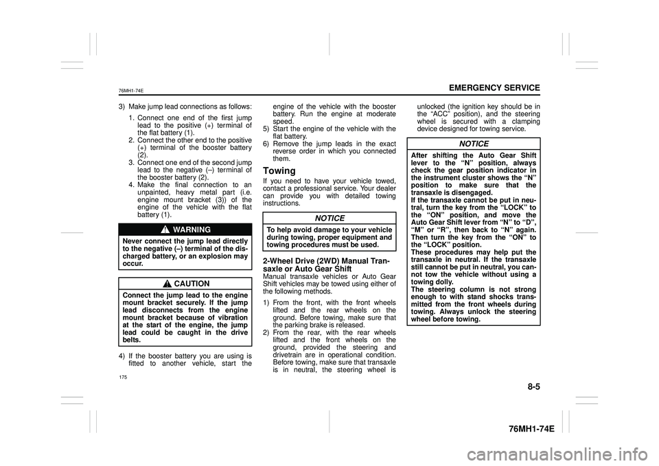
3) Make jump lead connections as follows:
1. Connect one end of the first jump lead to the positive (+) terminal of the flat battery (1). 2. Connect the other end to the positive(+) terminal of the booster battery (2). 3. Connect one end of the second jumplead to the negative (–) terminal of the booster battery (2). 4. Make the final connection to anunpainted, heavy metal part (i.e. engine mount bracket (3)) of the engine of the vehicle with the flatbattery (1).
4) If the booster battery you are using is fitted to another vehicle, start the
engine of the vehicle with the booster battery. Run the engine at moderate speed.5) Start the engine of the vehicle with the flat battery. 6) Remove the jump leads in the exactreverse order in which you connected them.
Towing
If you need to have your vehicle towed, contact a professional service. Your dealercan provide you with detailed towing instructions.
2-Wheel Drive (2WD) Manual Tran- saxle or Auto Gear ShiftManual transaxle vehicles or Auto Gear Shift vehicles may be towed using either of the following methods.
1) From the front, with the front wheels lifted and the rear wheels on the ground. Before towing, make sure thatthe parking brake is released. 2) From the rear, with the rear wheels lifted and the front wheels on theground, provided the steering and drivetrain are in operational condition. Before towing, make sure that transaxleis in neutral, the steering wheel is
unlocked (the ignition key should be in the “ACC” position), and the steering wheel is secured with a clampingdevice designed for towing service.
WA R N I N G
Never connect the jump lead directlyto the negative (–) terminal of the dis- charged battery, or an explosion may occur.
CAUTION
Connect the jump le ad to the engine mount bracket securely. If the jump lead disconnects from the engine mount bracket because of vibrationat the start of the engine, the jump lead could be caught in the drive belts.
NOTICE
To help avoid damage to your vehicle during towing, proper equipment and towing procedures must be used.
NOTICE
After shifting the Auto Gear Shiftlever to the “N” position, always check the gear position indicator in the instrument cluster shows the “N”position to make sure that the transaxle is disengaged. If the transaxle cannot be put in neu-tral, turn the key from the “LOCK” to the “ON” position, and move the Auto Gear Shift lever from “N” to “D”,“M” or “R”, then back to “N” again. Then turn the key from the “ON” to the “LOCK” position.These procedures may help put the transaxle in neutral. If the transaxle still cannot be put in neutral, you can-not tow the vehicle without using a towing dolly. The steering column is not strongenough to with stand shocks trans- mitted from the fr ont wheels during towing. Always unlock the steeringwheel before towing.
175