turn signal SUZUKI CELERIO 2022 User Guide
[x] Cancel search | Manufacturer: SUZUKI, Model Year: 2022, Model line: CELERIO, Model: SUZUKI CELERIO 2022Pages: 201, PDF Size: 5.82 MB
Page 135 of 201
5-39
OTHER CONTROLS AND EQUIPMENT
76MH1-74E
76MH1-74E
NOTE: To change your PIN, first delete your cur- rent PIN, then set a new one.
Confirming the Personal Identification Number (PIN)When the main power source is discon- nected such as when the battery is replaced, etc, it is required to enter the PINto make the unit operable again. 1) Set the ignition switch to the “ACC” position. “SECURITY” will be displayed. 2) Press the Up button (3) and the button numbered [1] of the Preset buttons (2)simultaneously. 3) Enter a 4-digit number to be registered as PIN using the buttons numbered [1] -[4] of the Preset buttons (2). 4) Hold down TUNE FOLDER PUSH SOUND knob (4) for 1 second or lon-ger. When the PIN same as registered is entered, the power of the audio systemwill be turned off automatically and it will become operable again.
NOTE: If an incorrect PIN is entered, “ERROR” and the total number of incorrect entryattempts will be displayed. If an incorrect PIN is entered 10 times, “HELP” will be displayed and the audiosystem will become inoperable.
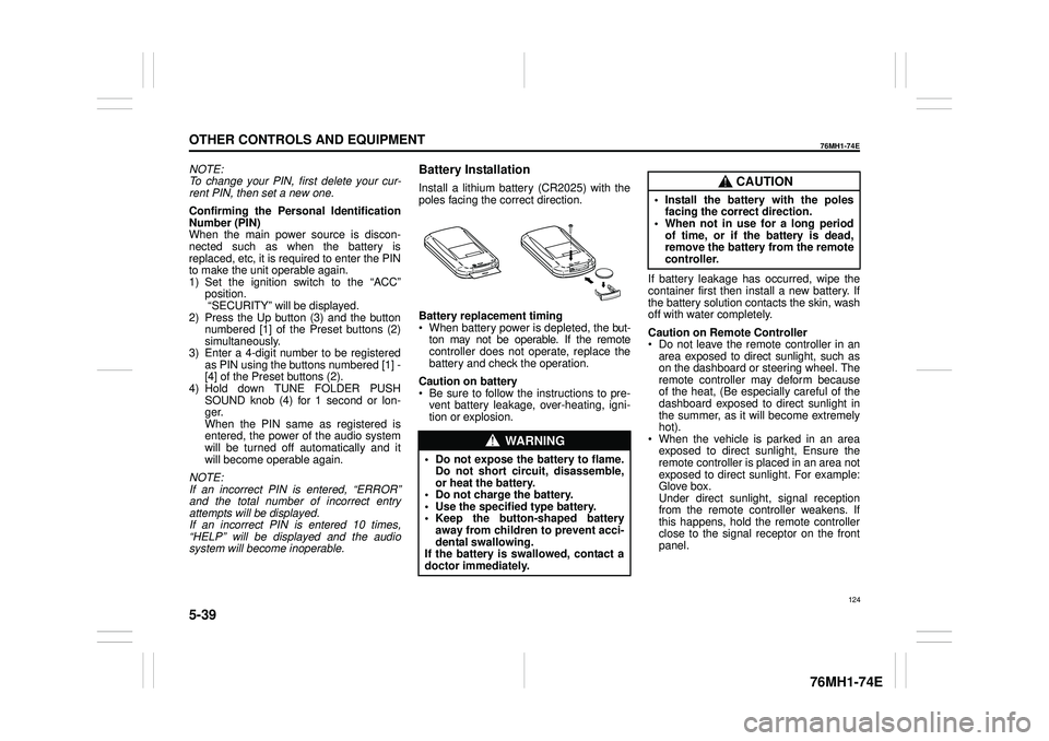
Battery Installation
Install a lithium battery (CR2025) with the poles facing the correct direction.
Battery replacement timing When battery power is depleted, the but-ton may not be operable. If the remote controller does not operate, replace the battery and check the operation.
Caution on battery Be sure to follow the instructions to pre- vent battery leakage, over-heating, igni- tion or explosion.
If battery leakage has occurred, wipe the container first then install a new battery. If the battery solution contacts the skin, wash off with water completely.
Caution on Remote Controller Do not leave the remote controller in anarea exposed to direct sunlight, such as on the dashboard or steering wheel. The remote controller may deform becauseof the heat, (Be especially careful of the dashboard exposed to direct sunlight in the summer, as it will become extremelyhot). When the vehicle is parked in an area exposed to direct sunlight, Ensure theremote controller is placed in an area not exposed to direct sunlight. For example: Glove box.Under direct sunlight , signal reception from the remote controller weakens. If this happens, hold the remote controllerclose to the signal receptor on the front panel.
WA R N I N G
• Do not expose the battery to flame. Do not short circuit, disassemble,or heat the battery. • Do not charge the battery. • Use the specified type battery.• Keep the button-shaped battery away from children to prevent acci- dental swallowing.If the battery is swallowed, contact a doctor immediately.
CAUTION
• Install the battery with the poles facing the correct direction.• When not in use for a long period of time, or if the battery is dead, remove the battery from the remotecontroller.
124
Page 137 of 201

5-41
OTHER CONTROLS AND EQUIPMENT
76MH1-74E
Radio operations
/TUNE VOL - VOL + FLD
/TUNE
MODEASSOUND
1
54
FLD
ENTSEEK TRACKSEEKTRACK
RPT RDM6
MENU3 2
DISP
NOTE: When there are fewer than 6 stations that can be stored even if 1 round of auto store operation is performed, no station will be stored at the remaining preset buttons.
Press to return to the last received fre- quency in the previous auto store mode. Press it for 2 seconds or longer. It selects the stations with the stronger signals andstores them in order.
AS button
Press to select the radio station.
SEEK TRACK UP/DOWN button
Press to select the desired preset station.
PRESET buttons (1-6)
126
Page 142 of 201
5-46
OTHER CONTROLS AND EQUIPMENT
76MH1-74E
76MH1-74E
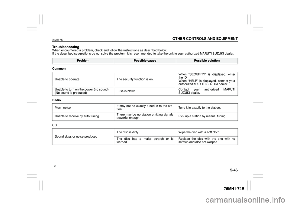
TroubleshootingWhen encountered a problem, check and follow the instructions as described below. If the described suggestions do not solve the problem, it is recommended to take the unit to your authorized MARUTI SUZUKI dealer.
ProblemPossible causePossible solution
Common
Unable to operate The security function is on.
When “SECURITY” is displayed, enter the ID. When “HELP” is displayed, contact yourauthorized MARUTI SUZUKI dealer.
Unable to turn on the power (no sound). (No sound is produced) Fuse is blown.Contact your authorized MARUTI SUZUKI dealer.
Radio
Much noise It may not be exactly tuned in to the sta- tion. Tune it in exactly to the station.
Unable to receive by auto tuning There may be no station emitting signals powerful enough. Pick up a station by manual tuning.
CD
Sound skips or noise produced
The disc is dirty. Wipe the disc with a soft cloth.
The disc has a major scratch or is warped. Replace the disc with the one with no scratch and also not warped.
131
Page 173 of 201
7-24
INSPECTION AND MAINTENANCE
76MH1-74E
76MH1-74E
Headlights
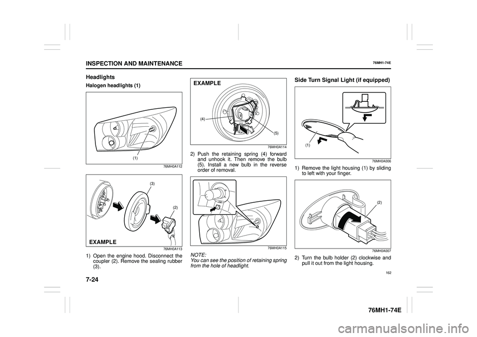
Halogen headlights (1)
76MH0A112
76MH0A113
1) Open the engine hood. Disconnect the coupler (2). Remove the sealing rubber(3).
76MH0A114
2) Push the retaining spring (4) forward and unhook it. Then remove the bulb(5). Install a new bulb in the reverse order of removal.
76MH0A115
NOTE: You can see the position of retaining springfrom the hole of headlight.
Side Turn Signal Light (if equipped)
76MH0A006
1) Remove the light housing (1) by sliding to left with your finger.
76MH0A007
2) Turn the bulb holder (2) clockwise and pull it out from the light housing.
(1)
(3)
(2)
EXAMPLE
(4)
(5)
EXAMPLE
(1)
(2)
162
Page 174 of 201
7-25
INSPECTION AND MAINTENANCE
76MH1-74E
76MH1-74E
76MH0A008
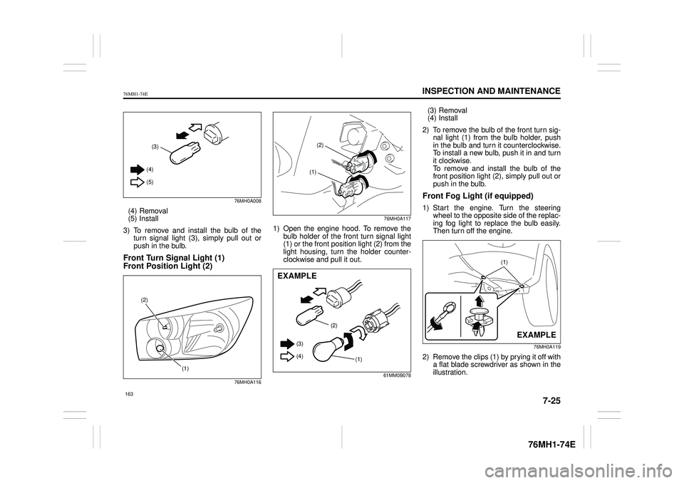
(4) Removal (5) Install
3) To remove and install the bulb of the turn signal light (3), simply pull out orpush in the bulb.
Front Turn Signal Light (1)
Front Position Light (2)
76MH0A116
76MH0A117
1) Open the engine hood. To remove the bulb holder of the front turn signal light (1) or the front position light (2) from thelight housing, turn the holder counter- clockwise and pull it out.
61MM0B078
(3) Removal(4) Install
2) To remove the bulb of the front turn sig- nal light (1) from the bulb holder, push in the bulb and turn it counterclockwise.To install a new bulb, push it in and turn it clockwise. To remove and install the bulb of thefront position light (2), simply pull out or push in the bulb.
Front Fog Light (if equipped)
1) Start the engine. Turn the steeringwheel to the opposite side of the replac- ing fog light to replace the bulb easily.Then turn off the engine.
76MH0A119
2) Remove the clips (1) by prying it off witha flat blade screwdriver as shown in theillustration.
(3)
(4)
(5)
(1)
(2)
(2)
(1)
(2)
(1)
(3)
(4)
EXAMPLE
(1)
EXAMPLE
163
Page 175 of 201
7-26
INSPECTION AND MAINTENANCE
76MH1-74E
76MH1-74E
76MH0A120
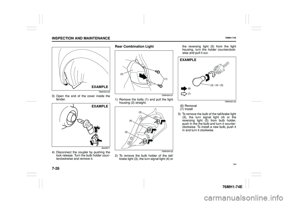
3) Open the end of the cover inside the fender.
80JM071
4) Disconnect the coupler by pushing the lock release. Turn the bulb holder coun- terclockwise and remove it.
Rear Combination Light
76MH0A121
1) Remove the bolts (1) and pull the light housing (2) straight.
76MH0A122
2) To remove the bulb holder of the tail/brake light (3), the turn signal light (4) or
the reversing light (5) from the light housing, turn the holder counterclock- wise and pull it out.
76MH0A123
(6) Removal (7) Install
3) To remove the bulb of the tail/brake light (3), the turn signal light (4) or the reversing light (5) from bulb holder,push in the the bulb and turn it counter- clockwise. To install a new bulb, push it in and turn it clockwise.
EXAMPLE
EXAMPLE
(2)
(1)
(3)
(4)
(5)
(3) / (4) / (5) (6)
(7)
EXAMPLE
164
Page 198 of 201
11-3
SPECIFICATIONS
76MH1-74E
76MH1-74E
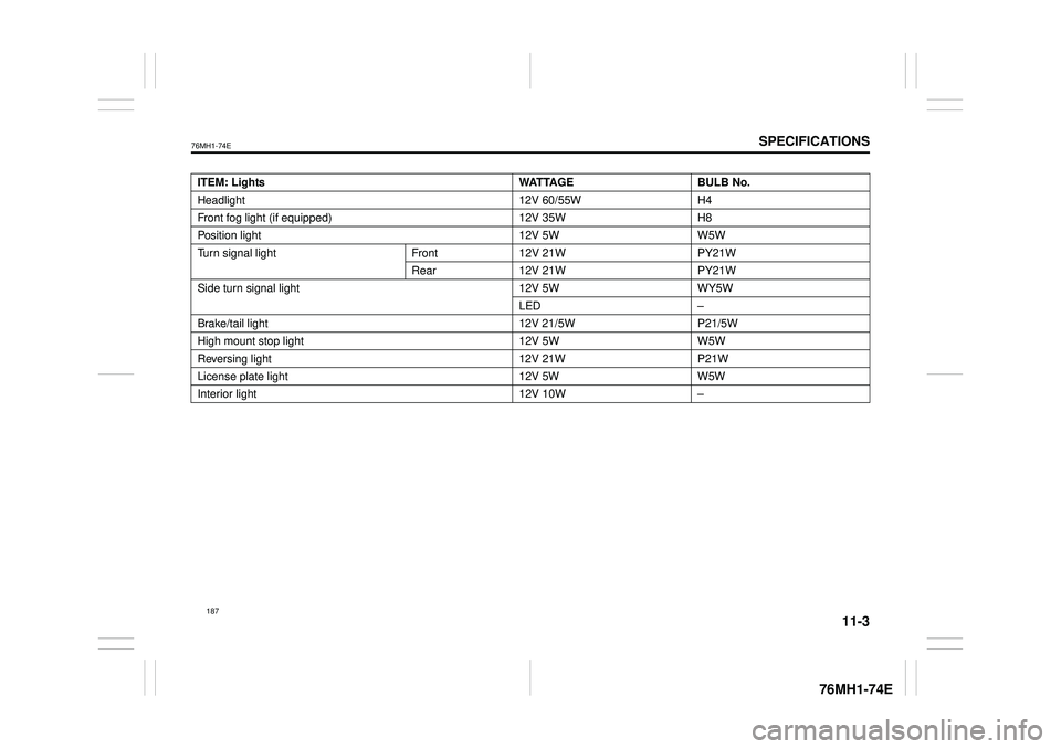
ITEM: Lights WATTAGE BULB No.
Headlight 12V 60/55W H4
Front fog light (if equipped) 12V 35W H8
Position light 12V 5W W5W
Turn signal light Front 12V 21W PY21W
Rear 12V 21W PY21W
Side turn signal light 12V 5W WY5W
LED –
Brake/tail light 12V 21/5W P21/5W
High mount stop light 12V 5W W5W
Reversing light 12V 21W P21W
License plate light 12V 5W W5W
Interior light 12V 10W –