brakes SUZUKI GRAND VITARA 1987 Service Repair Manual
[x] Cancel search | Manufacturer: SUZUKI, Model Year: 1987, Model line: GRAND VITARA, Model: SUZUKI GRAND VITARA 1987Pages: 962, PDF Size: 27.87 MB
Page 2 of 962

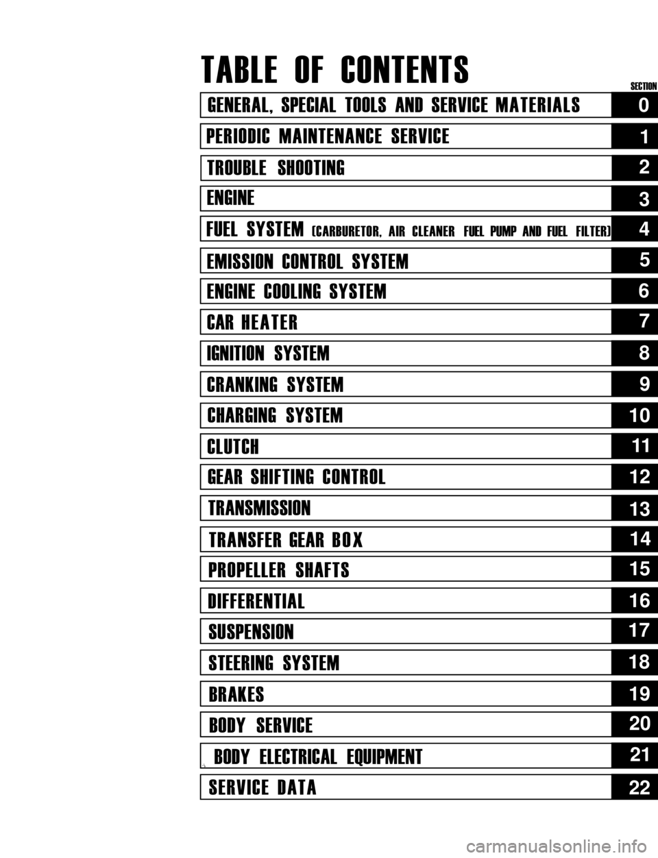
TABLE OF CONTENTS
GENERAL, SPECIAL TOOLS AND SERVICE MATERIALS
PERIODIC MAINTENANCE SERVICE
TROUBLE SHOOTING
ENGINE
FUEL SYSTEM (CARBURETOR, AIR CLEANER FUEL PUMP AND FUEL FILTER)
EMISSION CONTROL SYSTEM
ENGINE COOLING SYSTEM
CAR HEATER
IGNITION SYSTEM
CRANKING SYSTEM
CHARGING SYSTEM
CLUTCH
GEAR SHIFTING CONTROL
TRANSMISSION
TRANSFER GEAR BOX
PROPELLER SHAFTS
DIFFERENTIAL
SUSPENSION
STEERING SYSTEM
BRAKES
BODY SERVICE
,i BODY ELECTRICAL EQUIPMENT
SERVICE DATA
0
1
2
5
6
7
8
9
10
1111
12
13
14
15
16
17
18
19
20
21
22
4
3
SECTION
Page 39 of 962

2-1.
2-2.
2-3.
2-4.
2-5.
2-6.
2-7.
2-6.
2-9.
SECTION 2
TROUBLE SHOOTING
CONTENTS
ENGINE...................................................2-2
CARBURETOR...........................................
EXHAUST AND MUFFLER.................................
CLUTCH.................................................2-9
TRANSMISSION..........................................
DIFFERENTIALS.........................................2-11
PROPELLER SHAFTS.....................................2-12
BRAKES.............................................. 2-12
SUSPENSION, STEERING SYSTEM AND TIRES................
STARTING MOTOR.....................................
2-11. ALTERNATOR...........................................
FUEL METER............................................ 2-19
2-14. SPEEDOMETER..........................................2-19
2-15. WATER TEMPERATURE METER.............................2-19
2-9
2-9
2-10
2-14
2-16
2-17
2-18WIPER MOTOR.......................................
2-10.
2-12.
2-13.
2-1
2
Page 42 of 962

ConditionPossible causeCorrection
Not enough powerEmission control
1. Malfunctioning EGR valve
Check and replace as
necessary.
Check and replace as
2. Malfunctioning bowl vent solenoid valve.necessary.
Check and replace as
3. Malfunctioning high altitude switch.necessary
Check nad replace as
4. Malfunctioning throttle position switch
(wide open switch)
necessary
Others
1. Dragging brakes
2. Slipping clutch
.Repair or replace
Adjust or replace
Engine hesitatesAbnormal condition in electrical systems
(Momentary lack of1. Defective spark plug or plug gap out ofReplace or adjust gap
response as the acceler-
ator
adjustment
is depressed. Can2. Cracked rotor or cap in distributor,Replace
occur at all car speeds.resulting in leakage
Usually most severe3. Deteriorated ignition coil, or crackReplace
when first trying toresulting in leakage
make the car move, as4. Leaky high-tension cordsReplace
from a stop sign.)5. Ignition timing out of adjustmentAdjust as prescribed
Abnormal condition in fuel system
1. Improper adjustment of float level
2. Clogged carburetor jets
3. Malfunctioning accelerator pump
Adjust
Clean
Check and replace as
necessary
4. Inadequately discharging fuel pumpReplace
Abnormal condition in engine
1. Loss of compression pressure due to leaky
cylinder head gasket
Replace
2. Compression pressure too low because ofReplace and rebore as
worn pistons, rings, cylinders or burnt valvesnecessary
Emission control
1. Malfunctioning bowl vent solenoid valveCheck and replace as
necessary
2. Malfunctioning throttle position switch
(wide open switch)
3. Malfunctionnig high altitude switch
4. Malfunctioning EGR valve
Check and replace as
necessary
Check and replace as
necessary
Check and replace as
necessary
5. Malfunctioning thermostatically controlled
air cleaner
Check and replace as
necessary
2-4
Page 45 of 962

9
Cond it ionPossible causeCorrection
OverheatingAbnormal condition in ignition system
1. Improper ignition timingAdjust
2. Wrong heat value of spark plugsChange heat value
Abnormal condition in fuel systems
1. Float level set too lowAdjust
2. Clogged jets in carburetorClean
3. Loose inlet manifoldRetighten
Abnormal condition in cooling system,,
1. Not enough coolantRefill
2. Loose or broken fan beltAdjust or replace
3. Erratically working thermostatReplace
4. Poor water pump performanceReplace
5. Leaky radiator coresRepair or replace
Abnormal condition in lubrication system
1. Clogged oil filterReplace
2. Clogged oil strainerClean
3. Deteriorated oil pump performanceReplace
4. Oil leakage from oil pan or pumpRepair
5. Improper engine oil gradeReplace with proper grade
oil
6. Not enough oil in oil panReplenish
Others
1. Dragging brakesRepair or replace
2. Slipping clutchAdjust or replace
3. Blown cylinder head gasketReplace
Engine noiseCrankshaft noise
Note: Before check- 1. Worn-down bearings, resulting in excessivelyReplace
ing the mechanicallarge running clearances
noise, make sure that:2. Worn connecting-rod bearingsReplace
0 Ignition timing is3. Distorted connecting rodsRepair or replace
properly adjusted.4. Worn crankshaft journalsRepair by grinding, or re-
l Specified spark plugplace crankshaft
is used.5. Worn crankpins.Repair by grinding, or re-
l Specified fuel is used.place crankshaft
Noise due to pistons, rings, pins or cylinders
1. Abnormally worn cylinder boresRebore to next oversize
or replace
2. Worn pistons, rings or pinsReplace
3. Pistons tending to seizeReplace
4. Broken piston ringsReplace
, Others
1’. Excessively large camshaft thrust playReplace
2. Excessively large crankshaft thrust clearanceAdjust as prescribed
3. Valve clearance too largeAdjust as prescribed
4. Not enough engine oilReplenish
2-7
Page 46 of 962

ConditionPossible causeCorrection
High fuel consumptionAbnormal condition ignition system
1. Improper ignition timingAdjust
2. Leak or loose connection of high tension cordRepair or replace
3. Defective spark plug (improper gap, heavyClean, adjust or replace
deposits, and burned electrodes, etc..)
4. Cracked distributor cap or rotorReplace
5. Malfunctioning mechanical and vacuumCheck and repair or
advancers in distributorreplace
Abnormal condition in fuel system
1. Improper float levelAdjust
2. Fuel leakage from tank, pipe or carburetorRepair or replace
3. Malfunctioning carburetor choke systemRepair or replace
4. Dirty or clogged carburetor jetsClean
5. Clogged air cleaner elementClean or replace
6. Malfunctioning thermostatically controlledCheck and repair or
air cleanerreplace
Abnormal condition in engine
1. Low compressionPreviously outlined
2. Poor valve seatingRepair or replace
3. Improper valve clearanceAdjust
Emission control
1. Air leaks at exhaust manifoldTighten manifold bolts
and nuts.
Replace gasket.
2. Oxygen sensor out of orderReplace.
3. Water temperature switch out of orderReplace.
4. Malfunctioning throttle position switchReplace
5. Malfunctioning MCS (mixture controlReplace
solenoid) valve in carburetor
6. Malfunctioning EGR valveReplace
Others
1. Dragging brakesRepair or replace
2. Slipping clutchAdjust or replace
3. Improper tire pressureAdjust
Excessive engine oilOil leakage
consumption1. Loose oil drain plugTighten
2. Loose oil pan securing boltsTighten
3. Deteriorated or broken oil pan sealantReplace sealant
4. Leaky oil sealsReplace
5. Blown cylinder head gasketReplace
6. Improper tightening of oil filterTighten
7. Loose oil pressure switchTighten
2-8
Page 50 of 962

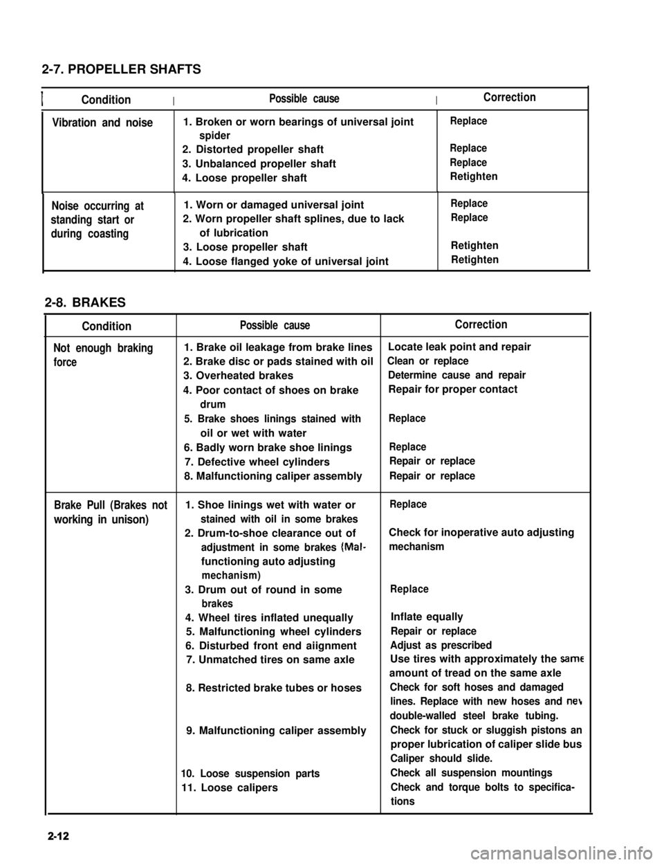
2-7. PROPELLER SHAFTS
IConditionIPossible causeICorrection
Vibration and noise1. Broken or worn bearings of universal joint
spider
2. Distorted propeller shaft
3. Unbalanced propeller shaft
4. Loose propeller shaft
Replace
Replace
Replace
Retighten
Noise occurring at
standing start or
during coasting
1. Worn or damaged universal joint
2. Worn propeller shaft splines, due to lack
of lubrication
3. Loose propeller shaft
4. Loose flanged yoke of universal joint
Replace
Replace
Retighten
Retighten
2-8. BRAKES
Condition
Not enough braking
force
Possible causeCorrection
1. Brake oil leakage from brake linesLocate leak point and repair
2. Brake disc or pads stained with oilClean or replace
3. Overheated brakesDetermine cause and repair
4. Poor contact of shoes on brakeRepair for proper contact
drum
5. Brake shoes linings stained with
oil or wet with water
Replace
6. Badly worn brake shoe liningsReplace
7. Defective wheel cylindersRepair or replace
8. Malfunctioning caliper assemblyRepair or replace
Brake Pull (Brakes not1. Shoe linings wet with water orReplace
working in unison)stained with oil in some brakes
2. Drum-to-shoe clearance out ofCheck for inoperative auto adjusting
adjustment in some brakes (Mal-mechanism
functioning auto adjusting
mechanism)
3. Drum out of round in some
brakes
Replace
4. Wheel tires inflated unequally
5. Malfunctioning wheel cylinders
6. Disturbed front end aiignment
7. Unmatched tires on same axle
8. Restricted brake tubes or hoses
9. Malfunctioning caliper assembly
10. Loose suspension parts
11. Loose calipers
Inflate equally
Repair or replace
Adjust as prescribed
Use tires with approximately the same
amount of tread on the same axle
Check for soft hoses and damaged
lines. Replace with new hoses and net
double-walled steel brake tubing.
Check for stuck or sluggish pistons an
proper lubrication of caliper slide bus
Caliper should slide.
Check all suspension mountings
Check and torque bolts to specifica-
tions
2-12
Page 51 of 962

Condition
Excessive pedal travel
(Pedal stroke too
large)
Possible cause
1. Partial brake system failure
2. Insufficient fluid in master
cylinder reservoirs
Correction
Check diagonal brake systems and
repair as necessary
Fill reservoirs with approved brake
fluid. Check for leaks and air in
brake systems. Check warning light.
Bleed system if necessary.
3. Air in system (Pedal soft/spongy)Bleed system
4. Rear brake system not adjustedAdjust rear brakes (Repair auto
(malfunctioning auto adjustingadjusting mechanism)
mechanism)
5. Bent brake shoesReplace brake shoes
6. Worn rear brake shoesReplace brake shoes.
Dragging brakes (A
very light drag is pre-
sent in all disc brakes
immediately after
pedal is released)
1. Master cylinder pistons not
returning correctly
2. Clogged return port in master
cylinder
3. Restricted brake tubes or hoses
4. Incorrect parking brake
adjustment
5. Weakened or broken return
springs in the brake
Repair master cylinder
Clean
Check for soft hoses or damaged tubes
and replace with new hoses and/or
new double-walled steel brake tubing
Check and adjust to correct specifica-
tions
Replace
6. Sluggish parking-brake cables or
linkage
Repair or replace
7. Wheel cylinder or caliper piston
sticking
Repair as necessary
Pedal pulsation1. Damaged or loose wheel bearingsReplace wheel bearings
(Pedal pulsates when2. Excessive disc lateral runout Check per instructions. If not within
depressed for braking)specifications, replace or machine the
disc.
3. Parallelism not within specifica-Check per instructions. If not within
tionsspecifications, replace or machine the
disc.
4. Rear drums out of roundCheck runout.
Braking noise1. Glazed shoe linings, or foreignRepair or replace shoe lining
matters stuck to linings
2. Worn or distorted shoe liningsReplace shoe lining (or pad)
3. Loose front wheel bearingsReplace wheel bearings
4. Distorted backing plates or looseReplace or retighten securing bolts
mounting bolts
2-13
Page 333 of 962

Side Bearings Caps
When putting on side bearing caps, be sure to
discriminate the right-hand cap from the left-
hand one by referring to match marks scribed
at the time of disassembly.
Then, after carrying out “Bevel gear backlash
adjustment” as described on p. 16-10 torque cap
bolts to specification.
16-6. INSTALLATION
Reverse removal procedure for installation,
noting the following.
Differential
Before installing differential ass’y to axle hous-
ing, clean mating surfaces of differential carrier
and housing and apply sealant to them.
Fig. 16-31 0 Scribed match marks
Fig. 16-32 @ Sealant (SUZUKI BOND NO.
1215 99000-31110)
Front Axle Shaft and Steering Knuckle
For installation them, refer to “Front Suspen-
sion Installation” in SECTION 17 of this manual.
Rear Brake Drum
For installation of rear brake drum, refer to
“Rear Brake Installation” in SECTION 19 of
this manual.
Differential Gear Oil
Refill differential housing with new specified
oil. Refer to “MAINTENANCE SERVICE” in
this section for refill.
Brake Circuit Air Purging
If brake pipe (right & left) was disconnected
from wheel cylinder as in Fig. 16-9-2, make sure
to purge air out of brake circuit. Refer to
section 19. BRAKES for “air purging" operation.
Then check to ensure that joint seam of pipe is
free from oil leak.
16-15
Page 386 of 962

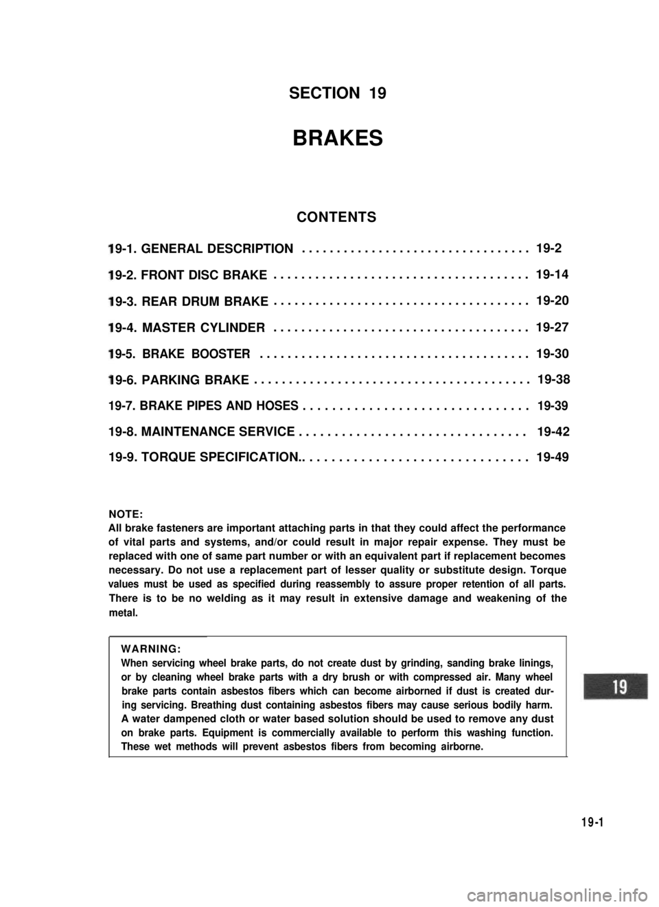
SECTION 19
BRAKES
CONTENTS
19-1. GENERAL DESCRIPTION................................. 19-2
19-2. FRONT DISC BRAKE..................................... 19-14
19-3. REAR DRUM BRAKE..................................... 19-20
19-4. MASTER CYLINDER..................................... 19-27
19-5. BRAKE BOOSTER....................................... 19-30
19-6. PARKING BRAKE........................................ 19-38
19-7. BRAKE PIPES AND HOSES . . . . . . . . . . . . . . . . . . . . . . . . . . . . . . . 19-39
19-8. MAINTENANCE SERVICE . . . . . . . . . . . . . . . . . . . . . . . . . . . . . . . . 19-42
19-9. TORQUE SPECIFICATION.. . . . . . . . . . . . . . . . . . . . . . . . . . . . . . . 19-49
NOTE:
All brake fasteners are important attaching parts in that they could affect the performance
of vital parts and systems, and/or could result in major repair expense. They must be
replaced with one of same part number or with an equivalent part if replacement becomes
necessary. Do not use a replacement part of lesser quality or substitute design. Torque
values must be used as specified during reassembly to assure proper retention of all parts.
There is to be no welding as it may result in extensive damage and weakening of the
metal.
WARNING:
When servicing wheel brake parts, do not create dust by grinding, sanding brake linings,
or by cleaning wheel brake parts with a dry brush or with compressed air. Many wheel
brake parts contain asbestos fibers which can become airborned if dust is created dur-
ing servicing. Breathing dust containing asbestos fibers may cause serious bodily harm.
A water dampened cloth or water based solution should be used to remove any dust
on brake parts. Equipment is commercially available to perform this washing function.
These wet methods will prevent asbestos fibers from becoming airborne.
19-1
Page 387 of 962

19-1. GENERAL DESCRIPTION
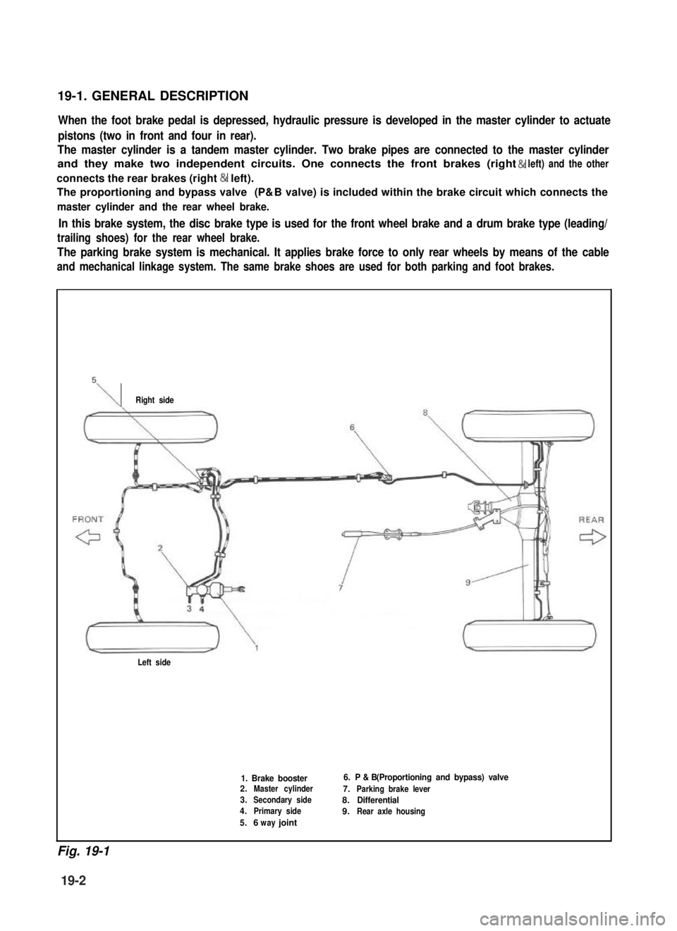
When the foot brake pedal is depressed, hydraulic pressure is developed in the master cylinder to actuate
pistons (two in front and four in rear).
The master cylinder is a tandem master cylinder. Two brake pipes are connected to the master cylinder
and they make two independent circuits. One connects the front brakes (right & left) and the other
connects the rear brakes (right & left).
The proportioning and bypass valve (P& B valve) is included within the brake circuit which connects the
master cylinder and the rear wheel brake.
In this brake system, the disc brake type is used for the front wheel brake and a drum brake type (leading/
trailing shoes) for the rear wheel brake.
The parking brake system is mechanical. It applies brake force to only rear wheels by means of the cable
and mechanical linkage system. The same brake shoes are used for both parking and foot brakes.
\Right side
Left side
1. Brake booster2.Master cylinder
3.Secondary side
4.Primary side
5.6 jointway
6. P & B (Proportioning and bypass) valve
7.Parking brake lever
8.Differential
9.Rear axle housing
Fig. 19-1
19-2