fuel cap SUZUKI GRAND VITARA 1987 Service Repair Manual
[x] Cancel search | Manufacturer: SUZUKI, Model Year: 1987, Model line: GRAND VITARA, Model: SUZUKI GRAND VITARA 1987Pages: 962, PDF Size: 27.87 MB
Page 27 of 962
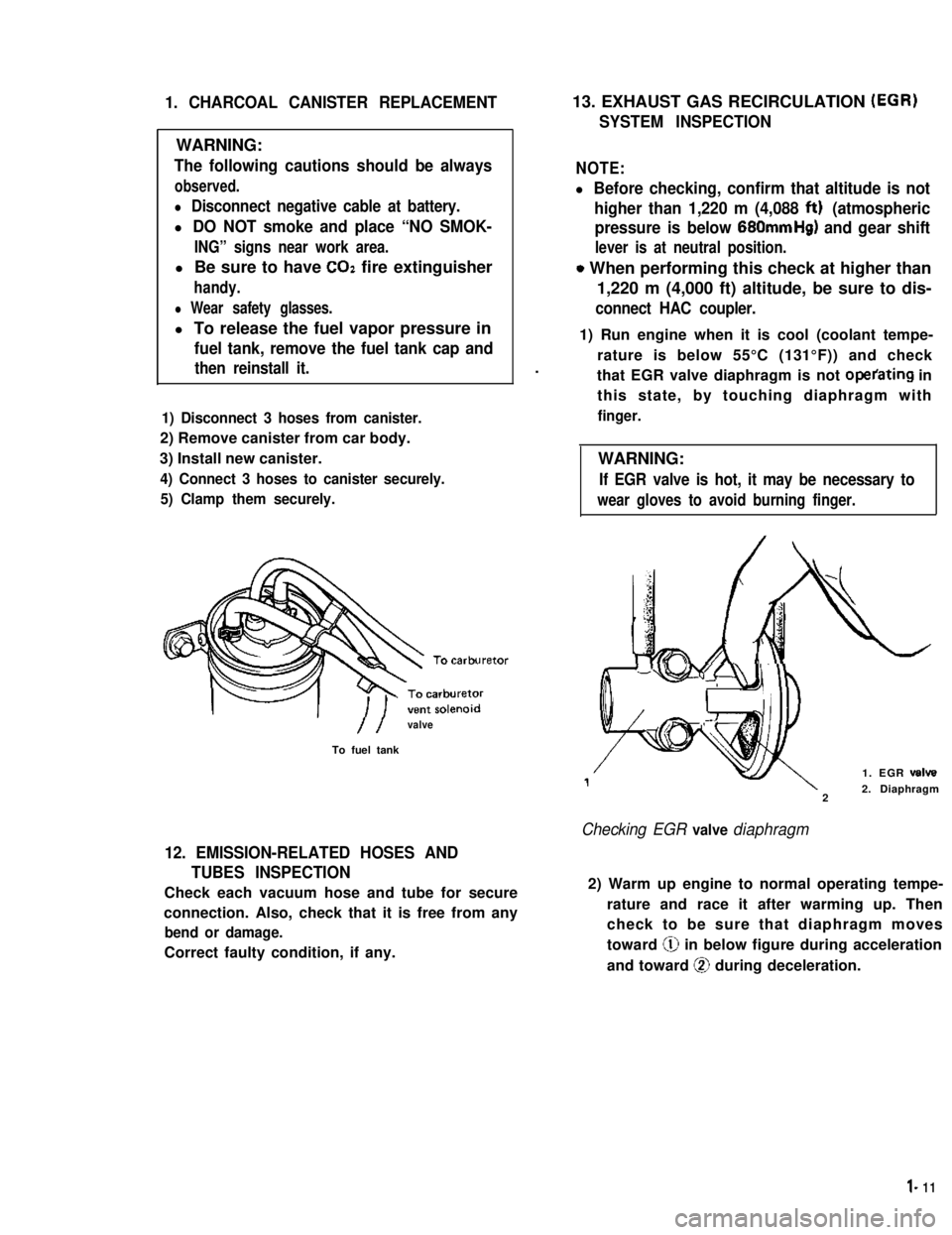
1. CHARCOAL CANISTER REPLACEMENT
WARNING:
The following cautions should be always
observed.
l Disconnect negative cable at battery.
l DO NOT smoke and place “NO SMOK-
ING” signs near work area.
l Be sure to have COZ fire extinguisher
handy.
l Wear safety glasses.
l To release the fuel vapor pressure in
fuel tank, remove the fuel tank cap and
then reinstall it.
1) Disconnect 3 hoses from canister.
2) Remove canister from car body.
3) Install new canister.
4) Connect 3 hoses to canister securely.
5) Clamp them securely.
//valve
To fuel tank
12. EMISSION-RELATED HOSES AND
TUBES INSPECTION
Check each vacuum hose and tube for secure
connection. Also, check that it is free from any
bend or damage.
Correct faulty condition, if any.
13. EXHAUST GAS RECIRCULATION (EGR)
SYSTEM INSPECTION
NOTE:
l Before checking, confirm that altitude is not
higher than 1,220 m (4,088 ftt) (atmospheric
pressure is below 680mmHg) and gear shift
lever is at neutral position.
o When performing this check at higher than
1,220 m (4,000 ft) altitude, be sure to dis-
connect HAC coupler.
.
1) Run engine when it is cool (coolant tempe-
rature is below 55°C (131°F)) and check
that EGR valve diaphragm is not operating in
this state, by touching diaphragm with
finger.
WARNING:
If EGR valve is hot, it may be necessary to
wear gloves to avoid burning finger.
1. EGR valve
22. Diaphragm
Checking EGR valve diaphragm
2) Warm up engine to normal operating tempe-
rature and race it after warming up. Then
check to be sure that diaphragm moves
toward @ in below figure during acceleration
and toward @ during deceleration.
l- 11
Page 30 of 962
21. FUEL TANK CAP GASKET INSPECTION
AND REPLACEMENT
Visually inspect gasket of fuel tank cap. If it is
damaged or deteriorated, replace it with new
one.
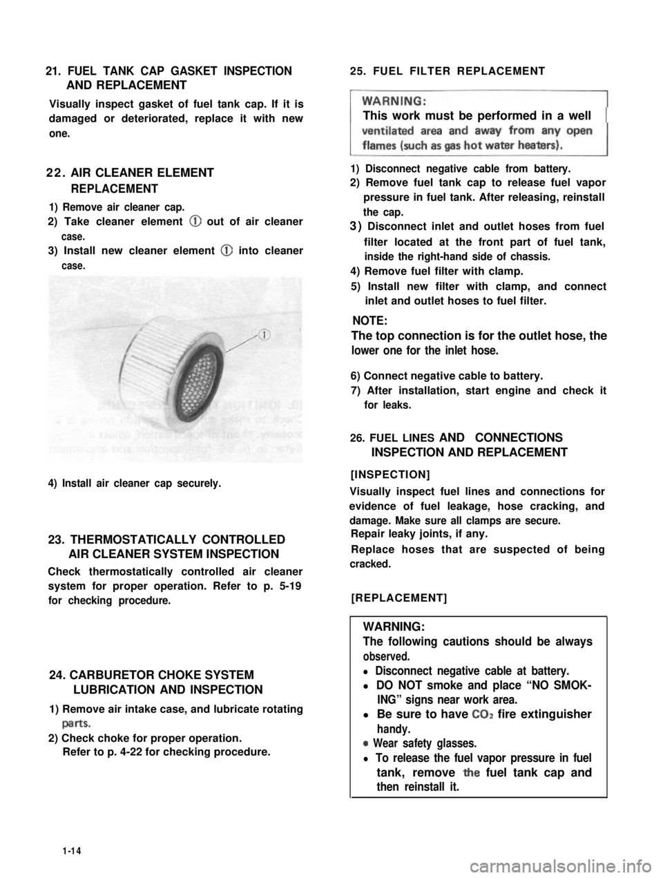
22. AIR CLEANER ELEMENT
REPLACEMENT
1) Remove air cleaner cap.
2) Take cleaner element @ out of air cleaner
case.
3) Install new cleaner element @ into cleaner
case.
4) Install air cleaner cap securely.
23. THERMOSTATICALLY CONTROLLED
AIR CLEANER SYSTEM INSPECTION
Check thermostatically controlled air cleaner
system for proper operation. Refer to p. 5-19
for checking procedure.
24. CARBURETOR CHOKE SYSTEM
LUBRICATION AND INSPECTION
1) Remove air intake case, and lubricate rotating
paItS.
2) Check choke for proper operation.
Refer to p. 4-22 for checking procedure.
25. FUEL FILTER REPLACEMENT
This work must be performed in a well
1) Disconnect negative cable from battery.
2) Remove fuel tank cap to release fuel vapor
pressure in fuel tank. After releasing, reinstall
the cap.
3) Disconnect inlet and outlet hoses from fuel
filter located at the front part of fuel tank,
inside the right-hand side of chassis.
4) Remove fuel filter with clamp.
5) Install new filter with clamp, and connect
inlet and outlet hoses to fuel filter.
NOTE:
The top connection is for the outlet hose, the
lower one for the inlet hose.
6) Connect negative cable to battery.
7) After installation, start engine and check it
for leaks.
26. FUEL LINES AND CONNECTIONS
INSPECTION AND REPLACEMENT
[INSPECTION]
Visually inspect fuel lines and connections for
evidence of fuel leakage, hose cracking, and
damage. Make sure all clamps are secure.
Repair leaky joints, if any.
Replace hoses that are suspected of being
cracked.
[REPLACEMENT]
WARNING:
The following cautions should be always
observed.
l Disconnect negative cable at battery.
l DO NOT smoke and place “NO SMOK-
ING” signs near work area.
l Be sure to have CO2 fire extinguisher
handy.
0 Wear safety glasses.
l To release the fuel vapor pressure in fuel
tank, remove the fuel tank cap and
then reinstall it.
1-14
Page 40 of 962

2-1. ENGINE
Cond it ion
Poor starting
(Hard starting)
Possible cause
Starter will not run
1. Main fuse blown off
2. Contact not closing in main switch, or this
switch open-circuited
3. Run-down battery
4. Defective magnetic switch of starter
5. Loose battery terminal connection
6. Defective brushes in starter
7. Loose battery cord connection
8. Open in field or armature circuit of starter.
Correction
Replace
Repair or replace
Recharge
Replace
Clean and retighten
Replace
Retighten
Repair or replace
No sparking
1. Defective spark plugAdjust gap, or replace
2. High tension cord short-circuited (grounded)Repair or replace
3. Cracked rotor or cap in distributorReplace
4. Defective signal generator or ignitorReplace
5. Maladjusted signal rotor air gap.Adjust
6. Contact not closing positively in main switch,Replace
or this switch open-circuited
7. Loose or blown fuseSet right or replace
8. Improper ignition timingAdjust
9. Defective ignition coil.Replace
Faulty intake and exhaust systems
1. Carburetor out of adjustment
2. Fuel pump not discharging adequately
3. Clogged fuel filter
4. Defective choke mechanism
5. Loose intake manifold
6. Dirty and clogged carburetor
7. Float level out of adjustment
8. Clogged fuel hose or pipe
9. Not enough fuel in the tank
10. Malfunctioning fuel cut solenoid valve
Adjust
Replace
Clean, or replace
Repair or replace
Retighten
Disassemble and clean
Adjust
Clean or replace
Refill
Check solenoid valve for
proper operation and
replace if necessary
Abnormal engine internal condition
1. Ruptured cylinder head gasket
2. Improper valve clearance
3. Weakened or broken valve spring
4. Loose manifold, permitting air to be
drawn in
5. Worn pistons, rings or cylinders
Replace
Adjust
Replace
Retighten and, as neces-
sary, replace gasket
Replace worn rings and
pistons and rebore as
necessary
2-2
Page 42 of 962

ConditionPossible causeCorrection
Not enough powerEmission control
1. Malfunctioning EGR valve
Check and replace as
necessary.
Check and replace as
2. Malfunctioning bowl vent solenoid valve.necessary.
Check and replace as
3. Malfunctioning high altitude switch.necessary
Check nad replace as
4. Malfunctioning throttle position switch
(wide open switch)
necessary
Others
1. Dragging brakes
2. Slipping clutch
.Repair or replace
Adjust or replace
Engine hesitatesAbnormal condition in electrical systems
(Momentary lack of1. Defective spark plug or plug gap out ofReplace or adjust gap
response as the acceler-
ator
adjustment
is depressed. Can2. Cracked rotor or cap in distributor,Replace
occur at all car speeds.resulting in leakage
Usually most severe3. Deteriorated ignition coil, or crackReplace
when first trying toresulting in leakage
make the car move, as4. Leaky high-tension cordsReplace
from a stop sign.)5. Ignition timing out of adjustmentAdjust as prescribed
Abnormal condition in fuel system
1. Improper adjustment of float level
2. Clogged carburetor jets
3. Malfunctioning accelerator pump
Adjust
Clean
Check and replace as
necessary
4. Inadequately discharging fuel pumpReplace
Abnormal condition in engine
1. Loss of compression pressure due to leaky
cylinder head gasket
Replace
2. Compression pressure too low because ofReplace and rebore as
worn pistons, rings, cylinders or burnt valvesnecessary
Emission control
1. Malfunctioning bowl vent solenoid valveCheck and replace as
necessary
2. Malfunctioning throttle position switch
(wide open switch)
3. Malfunctionnig high altitude switch
4. Malfunctioning EGR valve
Check and replace as
necessary
Check and replace as
necessary
Check and replace as
necessary
5. Malfunctioning thermostatically controlled
air cleaner
Check and replace as
necessary
2-4
Page 43 of 962
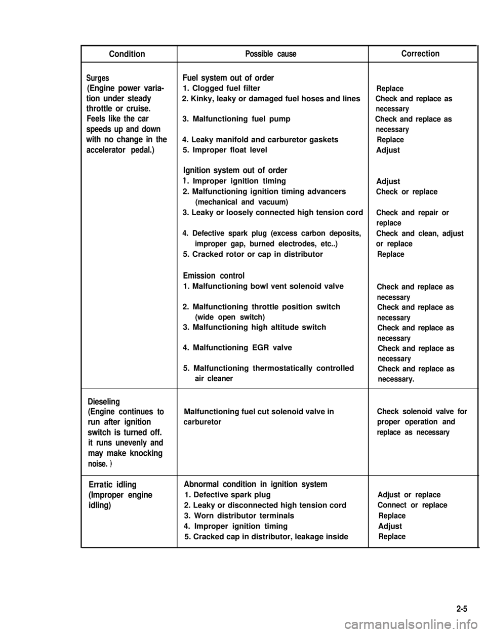
ConditionPossible causeCorrection
SurgesFuel system out of order
(Engine power varia- 1. Clogged fuel filterReplace
tion under steady2. Kinky, leaky or damaged fuel hoses and linesCheck and replace as
throttle or cruise.necessary
Feels like the car3. Malfunctioning fuel pumpCheck and replace as
speeds up and downnecessary
with no change in the4. Leaky manifold and carburetor gasketsReplace
accelerator pedal.)5. Improper float levelAdjust
Ignition system out of order
1. Improper ignition timing
2. Malfunctioning ignition timing advancers
(mechanical and vacuum)
Adjust
Check or replace
3. Leaky or loosely connected high tension cordCheck and repair or
replace
4. Defective spark plug (excess carbon deposits,Check and clean, adjust
improper gap, burned electrodes, etc..)or replace
5. Cracked rotor or cap in distributorReplace
Emission control
1. Malfunctioning bowl vent solenoid valve
2. Malfunctioning throttle position switch
(wide open switch)
3. Malfunctioning high altitude switch
4. Malfunctioning EGR valve
5. Malfunctioning thermostatically controlled
air cleaner
Check and replace as
necessary
Check and replace as
necessary
Check and replace as
necessary
Check and replace as
necessary
Check and replace as
necessary.
Dieseling
(Engine continues to
run after ignition
switch is turned off.
it runs unevenly and
may make knocking
noise. )
Malfunctioning fuel cut solenoid valve in
carburetor
Check solenoid valve for
proper operation and
replace as necessary
Erratic idling
(Improper engine
idling)
Abnormal condition in ignition system
1. Defective spark plug
2. Leaky or disconnected high tension cord
3. Worn distributor terminals
4. Improper ignition timing
5. Cracked cap in distributor, leakage inside
Adjust or replace
Connect or replace
Replace
Adjust
Replace
2-5
Page 46 of 962

ConditionPossible causeCorrection
High fuel consumptionAbnormal condition ignition system
1. Improper ignition timingAdjust
2. Leak or loose connection of high tension cordRepair or replace
3. Defective spark plug (improper gap, heavyClean, adjust or replace
deposits, and burned electrodes, etc..)
4. Cracked distributor cap or rotorReplace
5. Malfunctioning mechanical and vacuumCheck and repair or
advancers in distributorreplace
Abnormal condition in fuel system
1. Improper float levelAdjust
2. Fuel leakage from tank, pipe or carburetorRepair or replace
3. Malfunctioning carburetor choke systemRepair or replace
4. Dirty or clogged carburetor jetsClean
5. Clogged air cleaner elementClean or replace
6. Malfunctioning thermostatically controlledCheck and repair or
air cleanerreplace
Abnormal condition in engine
1. Low compressionPreviously outlined
2. Poor valve seatingRepair or replace
3. Improper valve clearanceAdjust
Emission control
1. Air leaks at exhaust manifoldTighten manifold bolts
and nuts.
Replace gasket.
2. Oxygen sensor out of orderReplace.
3. Water temperature switch out of orderReplace.
4. Malfunctioning throttle position switchReplace
5. Malfunctioning MCS (mixture controlReplace
solenoid) valve in carburetor
6. Malfunctioning EGR valveReplace
Others
1. Dragging brakesRepair or replace
2. Slipping clutchAdjust or replace
3. Improper tire pressureAdjust
Excessive engine oilOil leakage
consumption1. Loose oil drain plugTighten
2. Loose oil pan securing boltsTighten
3. Deteriorated or broken oil pan sealantReplace sealant
4. Leaky oil sealsReplace
5. Blown cylinder head gasketReplace
6. Improper tightening of oil filterTighten
7. Loose oil pressure switchTighten
2-8
Page 63 of 962
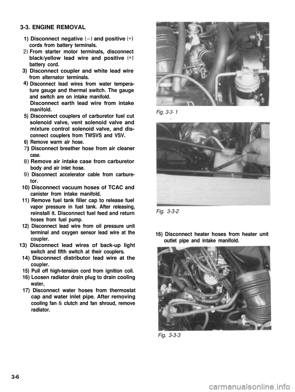
3-3. ENGINE REMOVAL
1) Disconnect negative (-) and positive (+)
cords from battery terminals.
‘)From starter motor terminals, disconnect
black/yellow lead wire and positive (+)
battery cord.
Disconnect coupler and white lead wire
from alternator terminals.
Disconnect lead wires from water tempera-
ture gauge and thermal switch. The gauge
and switch are on intake manifold.
Disconnect earth lead wire from intake
manifold.
5) Disconnect couplers of carburetor fuel cut
solenoid valve, vent solenoid valve and
mixture control solenoid valve, and dis-
connect couplers from TWSVS and VSV.
6) Remove warm air hose.
) Disconnect breather hose from air cleaner
case.
,) Remove air intake case from carburetor
body and air inlet hose.
1) Disconnect accelerator cable from carbure-
tor.
10) Disconnect vacuum hoses of TCAC and
canister from intake manifold.
11) Remove fuel tank filler cap to release fuel
vapor pressure in fuel tank. After releasing,
reinstall it. Disconnect fuel feed and return
hoses from fuel pump.
12) Disconnect lead wire from oil pressure unit
terminal and oxygen sensor lead wire at the
coupler.
13) Disconnect lead wires of back-up light
switch and fifth switch at their couplers.
14) Disconnect distributor lead wire at the
coupler.
15) Pull off high-tension cord from ignition coil.
16) Loosen radiator drain plug to drain cooling
water,
17) Disconnect water hoses from thermostat
cap and water inlet pipe. After removing
cooling fan & clutch and fan shroud, remove
radiator.
Fig. 3-3- 1
Fig. 3-3-2
16) Disconnect heater hoses from heater unit
outlet pipe and intake manifold.
Fig. 3-3-3
3)
4)
3-6
Page 115 of 962
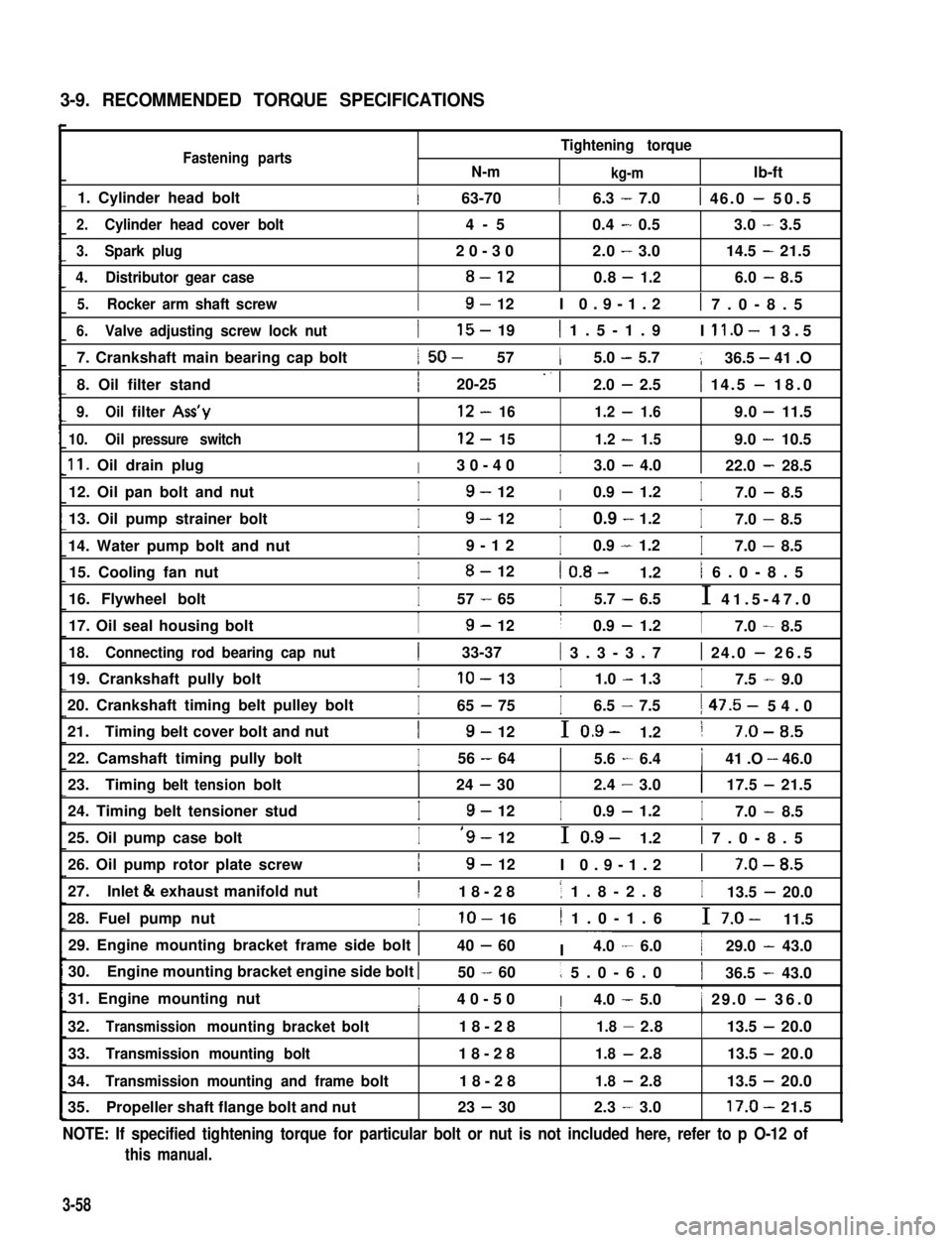
3-9. RECOMMENDED TORQUE SPECIFICATIONS
Fastening partsN-m
Tightening torque
kg-mlb-ft
1. Cylinder head bolt1 63-7016.3 - 7.01 46.0 - 50.5
2.Cylinder head cover bolt4-50.4-0.53.0-3.5
3.Spark plug20-302.0-3.014.5-21.5
4.Distributor gear case8-120.8-1.26.0-8.5
5.Rocker arm shaft screwI9- 12I 0.9-1.21 7.0-8.5
6.Valve adjusting screw lock nut
7. Crankshaft main bearing cap bolt
8. Oil filter stand
I15- 191 1.5-1.9I ll.O- 13.5
1 50- 5715.0 - 5.7136.5 - 41 .O
I20-25 -. 12.0 - 2.51 14.5 - 18.0
9.Oilfilter Ass’y12-161.2-1.69.0-11.5
10.Oilpressure switch12-151.2-1.59.0-10.5
11. Oil drain plugI30-40I3.0 - 4.0122.0 - 28.5
12. Oil pan bolt and nutI9- 12I0.9 - 1.2I7.0 - 8.5
13. Oil pump strainer bolt
14. Water pump bolt and nut
I9- 12I0.9 - 1.2I7.0 - 8.5
I9-12I0.9 - 1.2I7.0 - 8.5
15. Cooling fan nutI8- 121 0.8- 1.21 6.0-8.5
16. Flywheel boltI57 - 65I5.7 - 6.5I 41.5-47.0
17. Oil seal housing boltI9- 12I0.9 - 1.2I7.0 - 8.5
18.Connecting rod bearing cap nut1 33-37( 3.3-3.71 24.0 - 26.5
19. Crankshaft pully boltIlo- 13I1.0 - 1.3I7.5 - 9.0
20. Crankshaft timing belt pulley bolt
21.Timing belt cover bolt and nut
I65 - 75I6.5 - 7.51 47.5- 54.0
I9- 12I 0.9- 1.21 7-O-8.5
22. Camshaft timing pully boltI56 - 6415.6 - 6.4141 .O - 46.0III
23.Timingbelttensionbolt24-302.4-3.0117.5-21.5
24. Timing belt tensioner studI9- 12I0.9 - 1.2I7.0 - 8.5
25. Oil pump case boltI‘9- 12I 0.9- 1.21 7.0-8.5
26. Oil pump rotor plate screwI9- 12I 0.9-1.21 7-O-8.5
27.Inlet & exhaust manifold nutI18-281 1.8-2.8I13.5 - 20.0
28. Fuel pump nutIlo- 161 1.0-1.6I 7.0- 11.5
29. Engine mounting bracket frame side bolt 140 - 60I ~~~4.0 - 6.0129.0 - 43.0
30.Engine mounting bracket engine side bolt I50 - 601 5.0-6.0136.5 - 43.0
31. Engine mounting nutI40-50I4.0 - 5.01 29.0 - 36.0I1I
32.Transmissionmountingbracketbolt18-281.8-2.8113.5-20.0
33.Transmission mounting bolt18-281.8-2.813.5 -20.0
34.Transmission mounting and framebolt18-281.8-2.813.5 -20.0
35.Propeller shaft flange bolt and nut23 - 302.3-3.017.0-21.5
NOTE: If specified tightening torque for particular bolt or nut is not included here, refer to p O-12 of
this manual.
3-58
Page 127 of 962
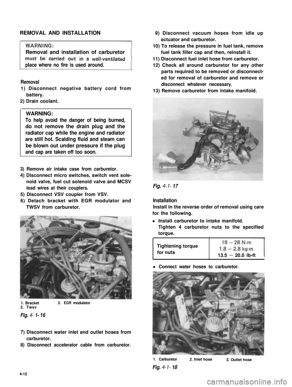
REMOVAL AND INSTALLATION
Removal and installation of carburetor
place where no fire is used around.
Removal
1) Disconnect negative battery cord from
battery.
2) Drain coolant.
WARNING:
To help avoid the danger of being burned,
do not remove the drain plug and the
radiator cap while the engine and radiator
are still hot. Scalding fluid and steam can
be blown out under pressure if the plug
and cap are taken off too soon.
3) Remove air intake case from carburetor.
4) Disconnect micro switches, switch vent sole-
noid valve, fuel cut solenoid valve and MCSV
lead wires at their couplers.
5) Disconnect VSV coupler from VSV.
6) Detach bracket with EGR modulator and
TWSV from carburetor.
1. Bracket3.EGRmodulator2. Twsv
Fig. 4- 1-16
7) Disconnect water inlet and outlet hoses from
carburetor.
8) Disconnect accelerator cable from carburetor.
9) Disconnect vacuum hoses from idle up
actuator and carburetor.
10) To release the pressure in fuel tank, remove
fuel tank filler cap and then, reinstall it.
11) Disconnect fuel inlet hose from carburetor.
12) Check all around carburetor for any other
parts required to be removed or disconnect-
ed for removal of carburetor and remove or
disconnect whatever necessary.
13) Remove carburetor from intake manifold.
Fig. 4- 7- 17
Installation
Install in the reverse order of removal using care
for the following.
l Install carburetor to intake manifold.
Tighten 4 carburetor nuts to the specified
torque.
Tightening torque
for nuts13.5 - 20.0 lb-ft
l Connect water hoses to carburetor.
1. Carburetor
Fig. 4- I- 18
2. Inlet hose3. Outlet hose
4-12
Page 144 of 962

4-2. AIR CLEANER
GENERAL DESCRIPTION
In the air cleaner case, a dry-type air cleaner element is provided for filtering.out dirt and dust from air
being drawn into the engine for combustion.
A damaged element must be replaced with a new one, since it allows dust particles to enter the engine if
used as it is. Such dust particles could cause wear to the engine inner parts and this further results in
decreased output.
Also, the element must be cleaned periodically. Dusty and dirty element causes decrease in output and
increase in fuel consumption. The dusty element even after cleaning should be replaced with a new one.
Fig. 4-2-l
1. Air cleaner case
2. Air cleaner case cap
3. Air cleaner element4. Air cleaner inlet hose
5. Air cleaner outlet hose
6. Warm air hose
7. Carburetor air intake case
8. Check valve
9. Therm0 sensor (valve)10. Air control actuator
MAINTENANCE SERVICES
Air Cleaner Element
[Cleaning]
1) Remove air cleaner outlet hose and case cap.
Fig. 4-2-21. Air cleaner outlet hose2. Air cleaner case cap3. Clamp
4-29