jump start SUZUKI GRAND VITARA 1987 Service Repair Manual
[x] Cancel search | Manufacturer: SUZUKI, Model Year: 1987, Model line: GRAND VITARA, Model: SUZUKI GRAND VITARA 1987Pages: 962, PDF Size: 27.87 MB
Page 244 of 962
![SUZUKI GRAND VITARA 1987 Service Repair Manual [Carrier and hold-down]
The battery carrier and hold-down clamp should
be clean and free from corrosion before instal-
ling the battery. The carrier should be in good
condition so that it will support SUZUKI GRAND VITARA 1987 Service Repair Manual [Carrier and hold-down]
The battery carrier and hold-down clamp should
be clean and free from corrosion before instal-
ling the battery. The carrier should be in good
condition so that it will support](/img/20/57437/w960_57437-243.png)
[Carrier and hold-down]
The battery carrier and hold-down clamp should
be clean and free from corrosion before instal-
ling the battery. The carrier should be in good
condition so that it will support the battery
securely and keep it level.
Make certain there are no parts in carrier before
installing the battery.
To prevent the battery from shaking in its
carrier, the hold-down bolts should be tight but
not over tightened.
[Visual inspection]
Check for obvious damage, such as cracked or
broken case or cover, that could permit loss of
electrolyte. If obvious damage is noted, replace
the battery. Determine cause of damage and
correct as needed.
Check the battery terminal and cords for corro-
sion. If any, it should be cleaned.
[Built-in indicator]
This sealed battery has a built-in temperature
compensated indicator in the top of the battery.
This indicator is to be used with the following
diagnostic procedure. When observing the
indicator, make sure that the battery has a clean
top. A light may be needed in some poorly-lit
areas.
Under normal operation, two indications can
be seen
2
Clear
RedCHARGING
NECESSARY
Fig. lo-23
l Clear with Red Dot
This means the discharging battery. In this case,
charge the battery until the indicator will be
blue with red dot. The charging and electrical
systems should also be checked at this time. If
any defective is found, correct it. While charging
it, if the battery feels hot 52°C (125” F), or if
violent gassing or spewing of electrolyte through
the vent hole occurs, discontinue charging or
reduce charging rate.
[Jump starting in case of emergency with
auxiliary (booster) battery]
NOTE:
l Do not push or tow the vehicle to start.
Damage to the emission system and/or to
other parts of the vehicle may result.
8 Both booster and discharged battery should
be treated carefully when using jumper cables.
Follow the procedure outlined below, being
careful not to cause sparks:
CAUTION:
l Departure from these conditions or the
procedure below could result in: (1)
Serious personal injury (particularly to
eyes) or property damage from such
causes as battery explosion, battery acid,
or electrical burns; and/or (2) damage to
electronic components of either vehicle.
l Never expose battery to open flame or
electric spark-batteries generate a gas
which is flammable and explosive.
l Remove rings,watches,and other
jewelry. Wear approved eye protection.
l Do not allow battery fluid to contact
eyes, skin, fabrics, or painted surfaces -
fluid is a corrosive acid. Flush any con-
tacted area with water immediately and
thoroughly. Be careful that metal tools
or jumper cables do not contact the
positive battery terminal (or metal in
contact with it) and any other metal on
the car, because a short circuit could
occur. Batteries should always be kept
out of the reach of children.
1) Set parking brake and place transmission in
neutral. Turn off the ignition, turn off lights
and all other electrical loads.
2) Check electrolyte level. If level is below low
level line, replace battery.
NOTE:
When jump starting an engine with charging
equipment, be sure equipment used is 12volt
and negative ground. Do not use 24volt charging
equipment. Using each equipment can cause
serious damage to the electrical system or
electronic parts.
10-11
Page 245 of 962

3) Attach the end of one jumper cable to the
positive terminal of the booster battery and
the other end of the same cable to the positive
terminal of the discharged battery. Do not
permit vehicles to touch each other as this
could cause a ground connection and counte-
ract the benefits of this procedure. (Use
12-volt battery only to jump start the engine).
4) Attach one end of the remaining negative
cable to the negative terminal of the booster
battery, and the other end to a solid engine
ground (such as A/C compressor bracket or
generator mounting bracket) at least 18 inches
from the battery of the vehicle being started
(DO NOT CONNECT DIRECTLY TO THE
NEGATIVE TERMINAL OF THE DEAD
BATTERY).
5) Start the engine of the vehicle that is provid-
ing the jump start and turn off electrical
accessories. Then start the engine in the car
with the discharged battery.
6) Reverse these directions exactly when remov-
ing the jumper cables. The negative cable
must be disconnected from the engine that
was jump started first.
REMOVE AND REPLACE
When handling a battery, the following safety
precautions should be followed:
1) Hydrogen gas is produced by the battery.
A flame or spark near the battery may cause
the gas to ignite.
2) Battery fluid is highly acidic. Avoid spilling
on clothing or other fabric. Any spilled
electrolyte should be flushed with large
quantity of water and cleaned immediately.
To remove or replace a battery, always
disconnect the negative cable first, then the
positive cable.
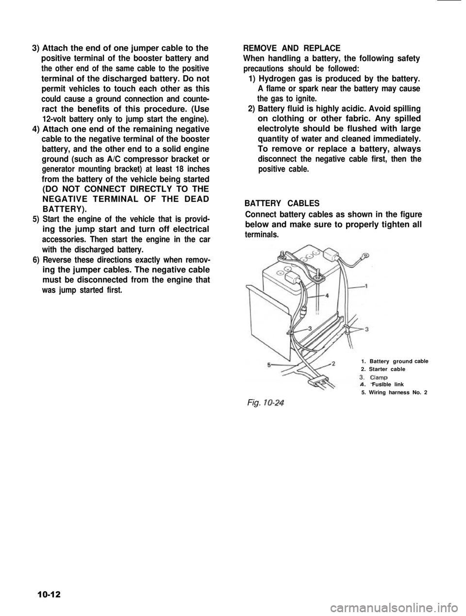
BATTERY CABLES
Connect battery cables as shown in the figure
below and make sure to properly tighten all
terminals.
1. Battery ground
2. Starter cable
4.Fusible link
cable
Fig. IO-24
5. Wiring harness No. 2
10-12
Page 271 of 962

10) Remove low gear bush, low speed synchro-
nizer hub, ring, spring, 2nd gear and 2nd
gear bearing by using hydraulic press.
Hydraulic press
Bush
Fig. 13-20
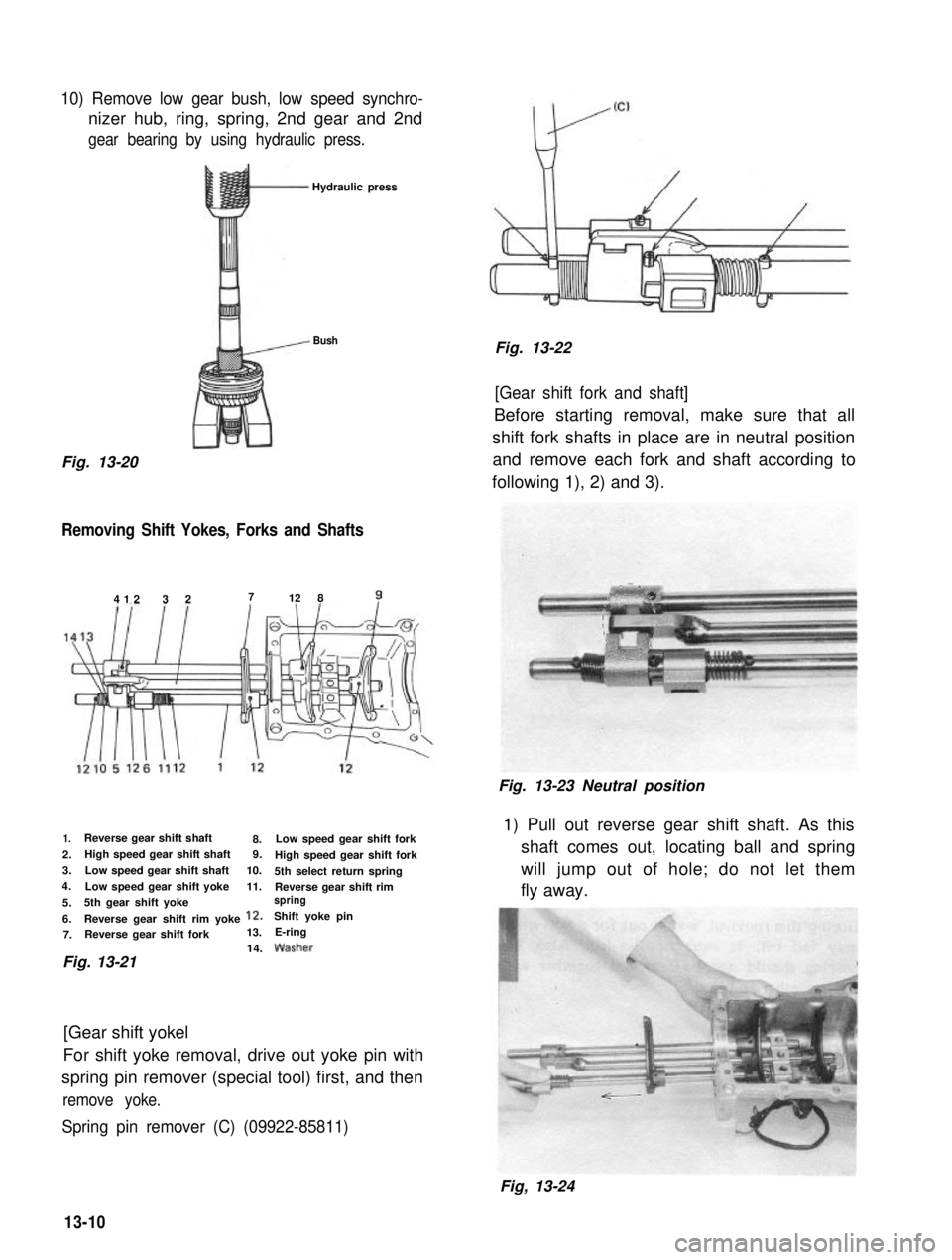
Removing Shift Yokes, Forks and Shafts
412 3 2712 8?
1.
2.
3.
4.
5.
6. 7. Reverse gear shift shaft
8.
Reverse gear shift rim yoke 12.
High speed gear shift shaft
9.
Reverse gear shift fork Low speed gear shift shaft
13.
10.
Low speed gear shift yoke 11.
5th gear shift yoke Low speed gear shift fork
Shift yoke pin High speed gear shift fork
5th select return spring Reverse gear shift rim
spring
E-ring
14.
Fig. 13-21
[Gear shift yokel
For shift yoke removal, drive out yoke pin with
spring pin remover (special tool) first, and then
remove yoke.
Spring pin remover (C) (09922-85811)
Fig. 13-22
[Gear shift fork and shaft]
Before starting removal, make sure that all
shift fork shafts in place are in neutral position and remove each fork and shaft according to
following 1), 2) and 3).
Fig. 13-23 Neutral position1) Pull out reverse gear shift shaft. As this shaft comes out, locating ball and spring
will jump out of hole; do not let them
fly away.
13-10
Fig, 13-24
Page 458 of 962

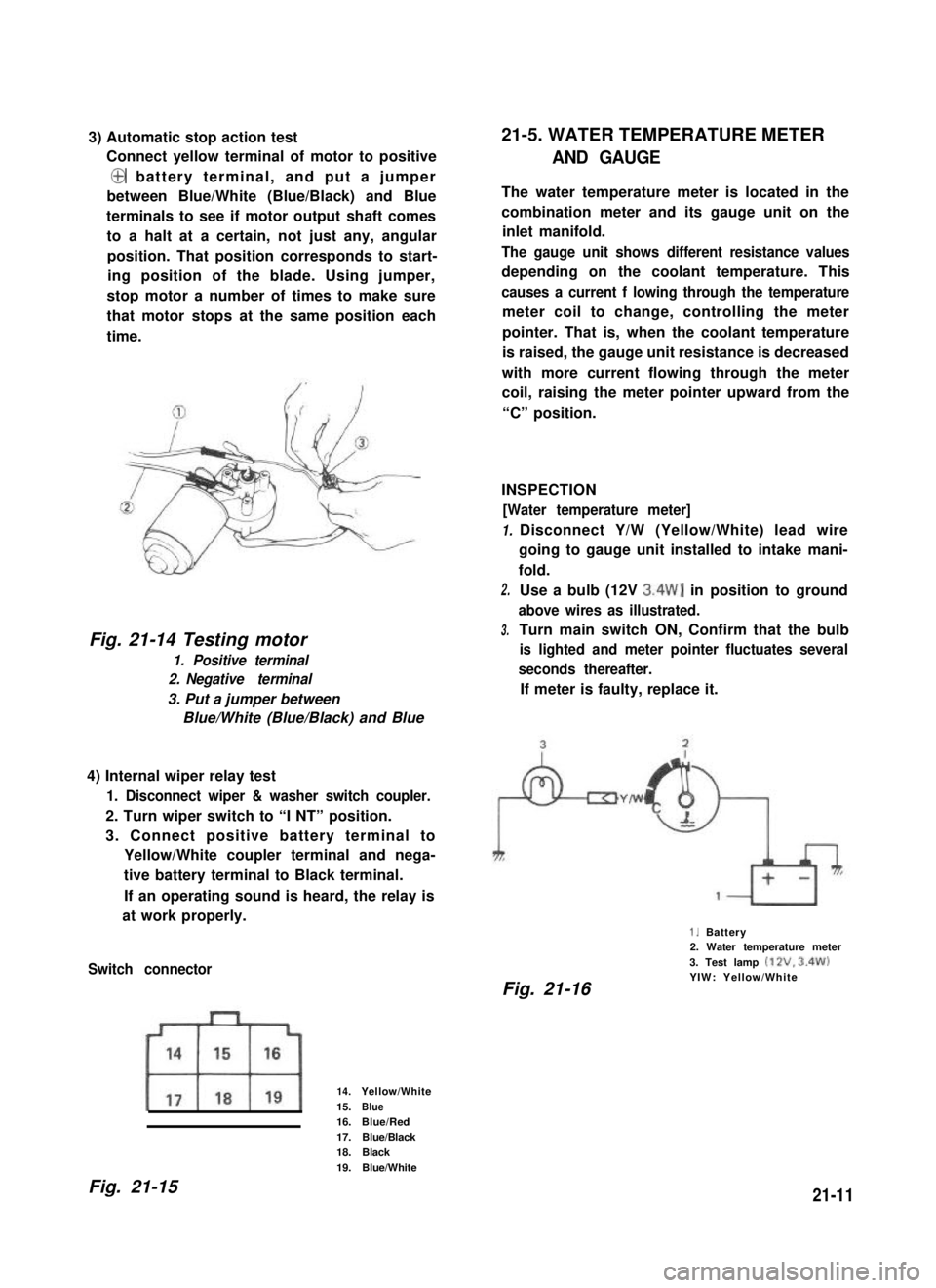
3) Automatic stop action test
Connect yellow terminal of motor to positive
@ battery terminal, and put a jumper
between Blue/White (Blue/Black) and Blue
terminals to see if motor output shaft comes
to a halt at a certain, not just any, angular
position. That position corresponds to start-
ing position of the blade. Using jumper,
stop motor a number of times to make sure
that motor stops at the same position each
time.
Fig. 21-14 Testing motor
1. Positive terminal
2. Negative terminal
3. Put a jumper between
Blue/White (Blue/Black) and Blue
4) Internal wiper relay test
1. Disconnect wiper & washer switch coupler.
2. Turn wiper switch to “I NT” position.
3. Connect positive battery terminal to
Yellow/White coupler terminal and nega-
tive battery terminal to Black terminal.
If an operating sound is heard, the relay is
at work properly.
Switch connector
14.Yellow/White
15.Blue16.Blue/Red17.Blue/Black
18.Black19.Blue/White
21-5. WATER TEMPERATURE METER
AND GAUGE
The water temperature meter is located in the
combination meter and its gauge unit on the
inlet manifold.
The gauge unit shows different resistance values
depending on the coolant temperature. This
causes a current f lowing through the temperature
meter coil to change, controlling the meter
pointer. That is, when the coolant temperature
is raised, the gauge unit resistance is decreased
with more current flowing through the meter
coil, raising the meter pointer upward from the
“C” position.
INSPECTION
[Water temperature meter]
1.
2.
3.
Disconnect Y/W (Yellow/White) lead wire
going to gauge unit installed to intake mani-
fold.
Use a bulb (12V 3.4W) in position to ground
above wires as illustrated.
Turn main switch ON, Confirm that the bulb
is lighted and meter pointer fluctuates several
seconds thereafter.
If meter is faulty, replace it.
1. Battery2. Water temperature meter
3. Test lamp (12V. 3.4W)YIW: Yellow/WhiteFig. 21-16
Fig. 21-1521-11