jump start terminals SUZUKI GRAND VITARA 1987 Service Repair Manual
[x] Cancel search | Manufacturer: SUZUKI, Model Year: 1987, Model line: GRAND VITARA, Model: SUZUKI GRAND VITARA 1987Pages: 962, PDF Size: 27.87 MB
Page 245 of 962

3) Attach the end of one jumper cable to the
positive terminal of the booster battery and
the other end of the same cable to the positive
terminal of the discharged battery. Do not
permit vehicles to touch each other as this
could cause a ground connection and counte-
ract the benefits of this procedure. (Use
12-volt battery only to jump start the engine).
4) Attach one end of the remaining negative
cable to the negative terminal of the booster
battery, and the other end to a solid engine
ground (such as A/C compressor bracket or
generator mounting bracket) at least 18 inches
from the battery of the vehicle being started
(DO NOT CONNECT DIRECTLY TO THE
NEGATIVE TERMINAL OF THE DEAD
BATTERY).
5) Start the engine of the vehicle that is provid-
ing the jump start and turn off electrical
accessories. Then start the engine in the car
with the discharged battery.
6) Reverse these directions exactly when remov-
ing the jumper cables. The negative cable
must be disconnected from the engine that
was jump started first.
REMOVE AND REPLACE
When handling a battery, the following safety
precautions should be followed:
1) Hydrogen gas is produced by the battery.
A flame or spark near the battery may cause
the gas to ignite.
2) Battery fluid is highly acidic. Avoid spilling
on clothing or other fabric. Any spilled
electrolyte should be flushed with large
quantity of water and cleaned immediately.
To remove or replace a battery, always
disconnect the negative cable first, then the
positive cable.
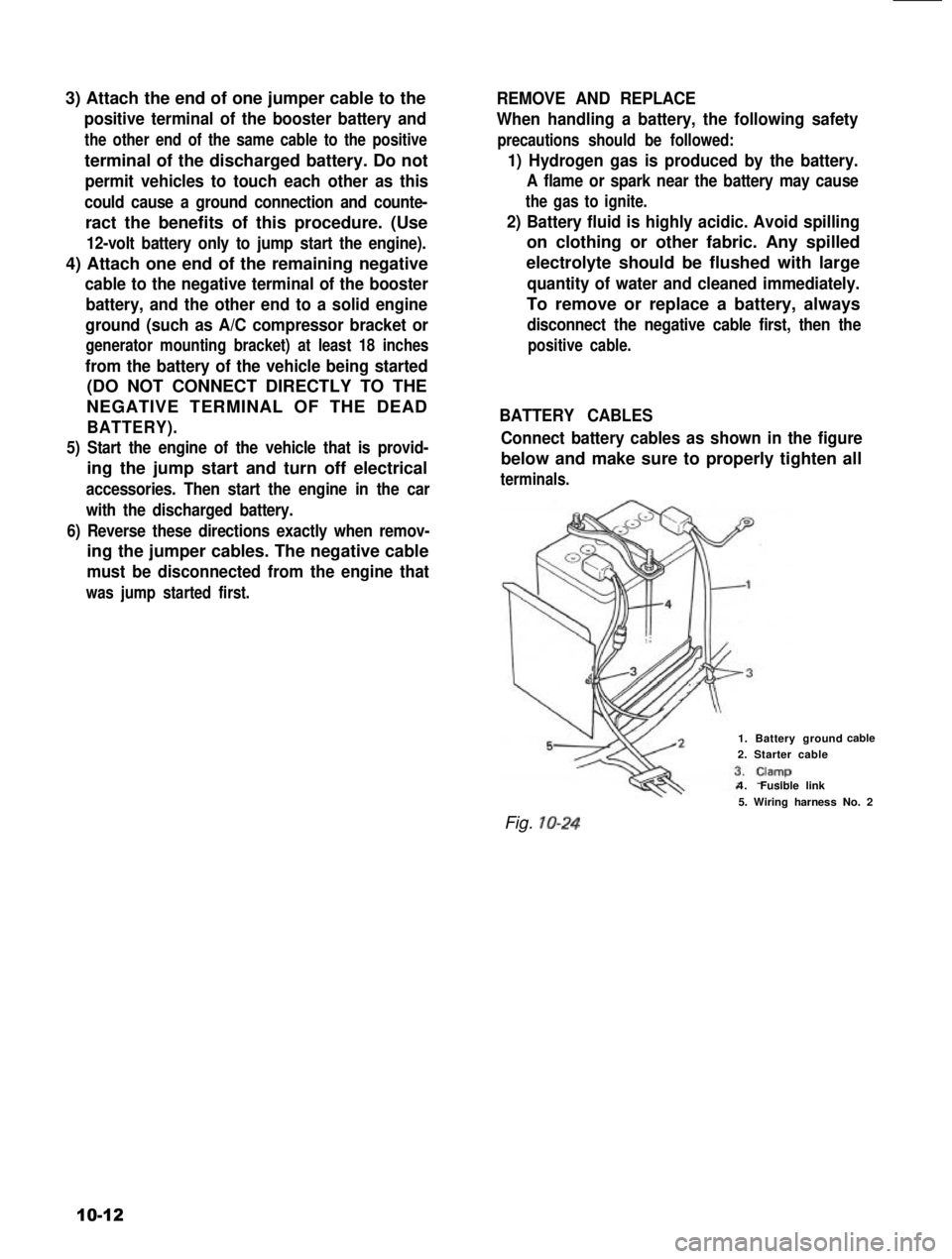
BATTERY CABLES
Connect battery cables as shown in the figure
below and make sure to properly tighten all
terminals.
1. Battery ground
2. Starter cable
4.Fusible link
cable
Fig. IO-24
5. Wiring harness No. 2
10-12
Page 458 of 962

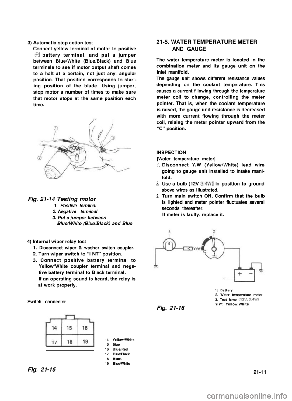
3) Automatic stop action test
Connect yellow terminal of motor to positive
@ battery terminal, and put a jumper
between Blue/White (Blue/Black) and Blue
terminals to see if motor output shaft comes
to a halt at a certain, not just any, angular
position. That position corresponds to start-
ing position of the blade. Using jumper,
stop motor a number of times to make sure
that motor stops at the same position each
time.
Fig. 21-14 Testing motor
1. Positive terminal
2. Negative terminal
3. Put a jumper between
Blue/White (Blue/Black) and Blue
4) Internal wiper relay test
1. Disconnect wiper & washer switch coupler.
2. Turn wiper switch to “I NT” position.
3. Connect positive battery terminal to
Yellow/White coupler terminal and nega-
tive battery terminal to Black terminal.
If an operating sound is heard, the relay is
at work properly.
Switch connector
14.Yellow/White
15.Blue16.Blue/Red17.Blue/Black
18.Black19.Blue/White
21-5. WATER TEMPERATURE METER
AND GAUGE
The water temperature meter is located in the
combination meter and its gauge unit on the
inlet manifold.
The gauge unit shows different resistance values
depending on the coolant temperature. This
causes a current f lowing through the temperature
meter coil to change, controlling the meter
pointer. That is, when the coolant temperature
is raised, the gauge unit resistance is decreased
with more current flowing through the meter
coil, raising the meter pointer upward from the
“C” position.
INSPECTION
[Water temperature meter]
1.
2.
3.
Disconnect Y/W (Yellow/White) lead wire
going to gauge unit installed to intake mani-
fold.
Use a bulb (12V 3.4W) in position to ground
above wires as illustrated.
Turn main switch ON, Confirm that the bulb
is lighted and meter pointer fluctuates several
seconds thereafter.
If meter is faulty, replace it.
1. Battery2. Water temperature meter
3. Test lamp (12V. 3.4W)YIW: Yellow/WhiteFig. 21-16
Fig. 21-1521-11