sensor SUZUKI GRAND VITARA 1987 Service Repair Manual
[x] Cancel search | Manufacturer: SUZUKI, Model Year: 1987, Model line: GRAND VITARA, Model: SUZUKI GRAND VITARA 1987Pages: 962, PDF Size: 27.87 MB
Page 26 of 962
8. PCV VALVE REPLACEMENT
1) Disconnect crankcase ventilation hose from
PCV valve.
2) Remove PCV valve from intake manifold.
3) Wind sealing tape on thread of the new valve
and install it securely.
Tightenlng torque
for PCV valve
15-25 N.m
1.5-2.5 kg-m,
11 .O-18.0 lb-ft
4) Install hose and clamp it securely.
9. OXYGEN SENSOR REPLACEMENT
[Canadian specification vehicle]
When the odometer indicates 50,000 and 100,000
miles, replace oxygen sensor as follows.
CAUTION:
To avoid the danger of being burned, do
not touch the exhaust system when the
system is hot. This work should be perform-
ed when the system is cool.
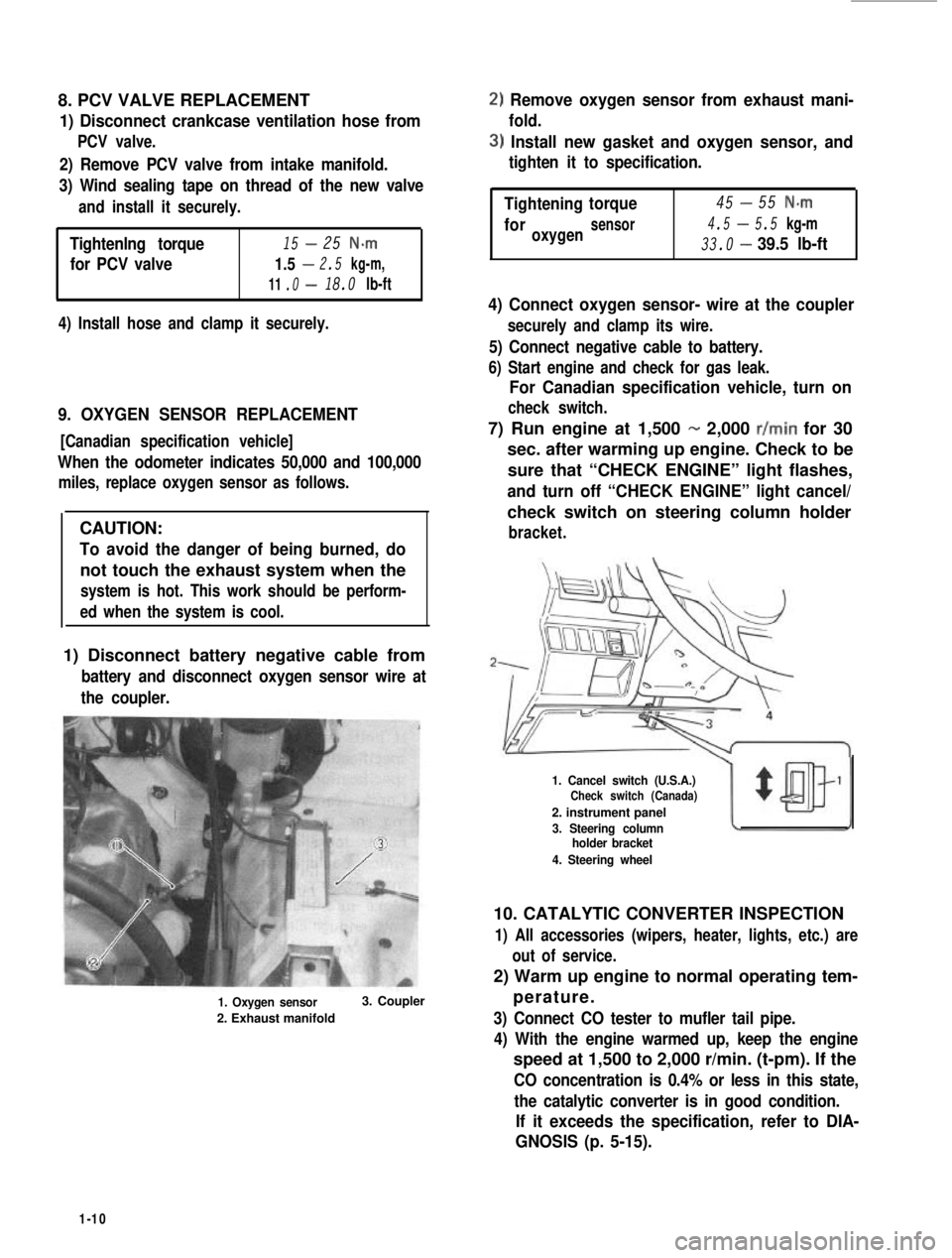
1) Disconnect battery negative cable from
battery and disconnect oxygen sensor wire at
the coupler.
1. Oxygen sensor
2. Exhaust manifold
3. Coupler
2) Remove oxygen sensor from exhaust mani-
fold.
3) Install new gasket and oxygen sensor, and
tighten it to specification.
-Tightening45torque55 N-m
4.5-foroxygensensor5.5 kg-m
33.0-39.5 lb-ft
4) Connect oxygen sensor- wire at the coupler
securely and clamp its wire.
5) Connect negative cable to battery.
6) Start engine and check for gas leak.
For Canadian specification vehicle, turn on
check switch.
7) Run engine at 1,500 - 2,000 r/min for 30
sec. after warming up engine. Check to be
sure that “CHECK ENGINE” light flashes,
and turn off “CHECK ENGINE” light cancel/
check switch on steering column holder
bracket.
1. Cancel switch (U.S.A.)Check switch (Canada)
2. instrument panel
3. Steering columnholder bracket
4. Steering wheel
10. CATALYTIC CONVERTER INSPECTION
1) All accessories (wipers, heater, lights, etc.) are
out of service.
2) Warm up engine to normal operating tem-
perature.
3) Connect CO tester to mufler tail pipe.
4) With the engine warmed up, keep the engine
speed at 1,500 to 2,000 r/min. (t-pm). If the
CO concentration is 0.4% or less in this state,
the catalytic converter is in good condition.
If it exceeds the specification, refer to DIA-
GNOSIS (p. 5-15).
1-10
Page 28 of 962
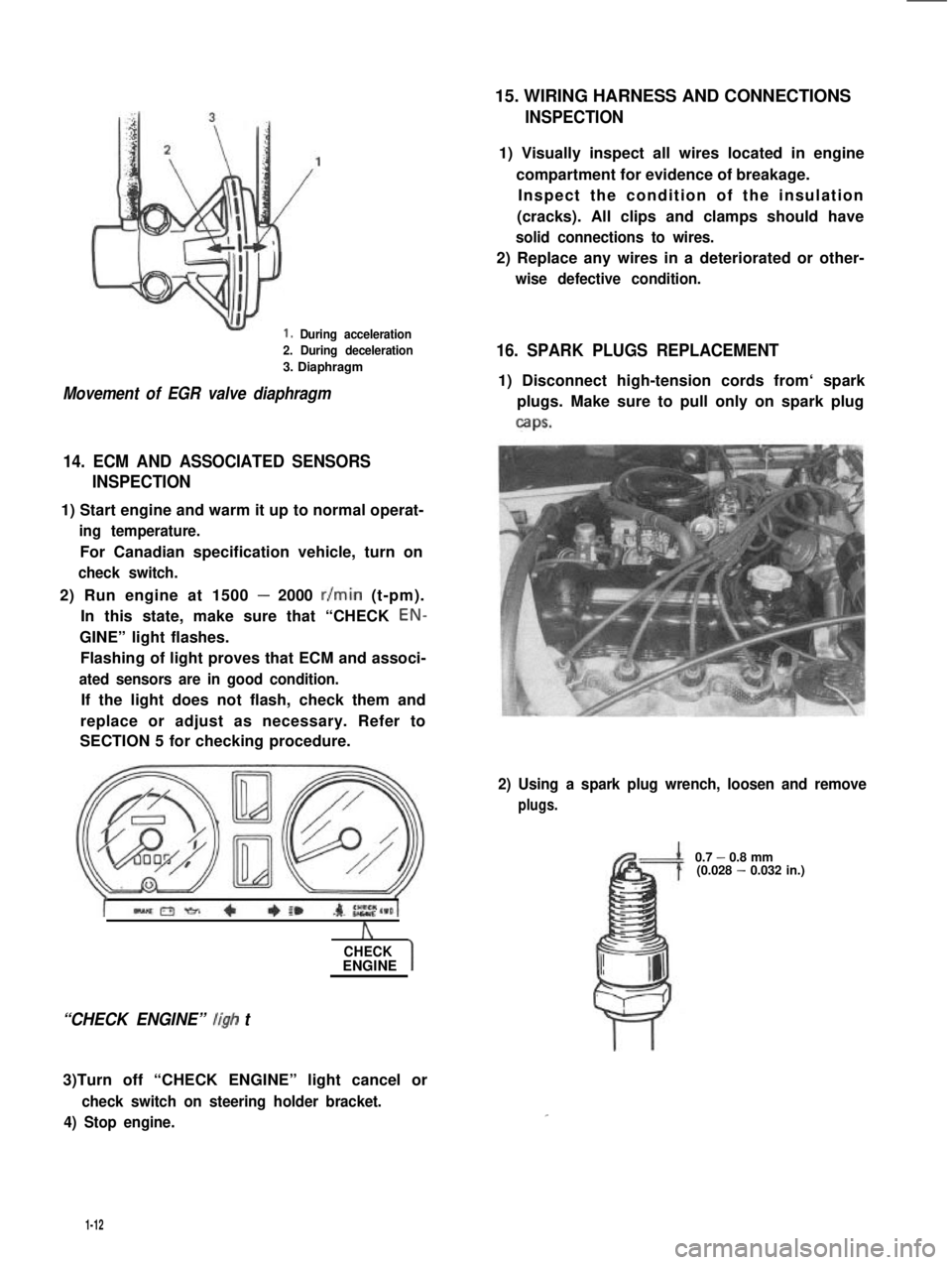
1. During acceleration
2. During deceleration
3. Diaphragm
Movement of EGR valve diaphragm
14. ECM AND ASSOCIATED SENSORS
INSPECTION
1) Start engine and warm it up to normal operat-
ing temperature.
For Canadian specification vehicle, turn on
check switch.
2) Run engine at 1500 - 2000 r/min (t-pm).
In this state, make sure that “CHECK EON-
GINE” light flashes.
Flashing of light proves that ECM and associ-
ated sensors are in good condition.
If the light does not flash, check them and
replace or adjust as necessary. Refer to
SECTION 5 for checking procedure.
A
CHECKENGINE
“CHECK ENGINE” ligh t
3)Turn off “CHECK ENGINE” light cancel or
check switch on steering holder bracket.
4) Stop engine.
15. WIRING HARNESS AND CONNECTIONS
INSPECTION
1) Visually inspect all wires located in engine
compartment for evidence of breakage.
Inspect the condition of the insulation
(cracks). All clips and clamps should have
solid connections to wires.
2) Replace any wires in a deteriorated or other-
wise defective condition.
16. SPARK PLUGS REPLACEMENT
1) Disconnect high-tension cords from‘ spark
plugs. Make sure to pull only on spark plug
caps.
2) Using a spark plug wrench, loosen and remove
plugs.
0.7 - 0.8 mm(0.028 - 0.032 in.)
1-12
Page 46 of 962

ConditionPossible causeCorrection
High fuel consumptionAbnormal condition ignition system
1. Improper ignition timingAdjust
2. Leak or loose connection of high tension cordRepair or replace
3. Defective spark plug (improper gap, heavyClean, adjust or replace
deposits, and burned electrodes, etc..)
4. Cracked distributor cap or rotorReplace
5. Malfunctioning mechanical and vacuumCheck and repair or
advancers in distributorreplace
Abnormal condition in fuel system
1. Improper float levelAdjust
2. Fuel leakage from tank, pipe or carburetorRepair or replace
3. Malfunctioning carburetor choke systemRepair or replace
4. Dirty or clogged carburetor jetsClean
5. Clogged air cleaner elementClean or replace
6. Malfunctioning thermostatically controlledCheck and repair or
air cleanerreplace
Abnormal condition in engine
1. Low compressionPreviously outlined
2. Poor valve seatingRepair or replace
3. Improper valve clearanceAdjust
Emission control
1. Air leaks at exhaust manifoldTighten manifold bolts
and nuts.
Replace gasket.
2. Oxygen sensor out of orderReplace.
3. Water temperature switch out of orderReplace.
4. Malfunctioning throttle position switchReplace
5. Malfunctioning MCS (mixture controlReplace
solenoid) valve in carburetor
6. Malfunctioning EGR valveReplace
Others
1. Dragging brakesRepair or replace
2. Slipping clutchAdjust or replace
3. Improper tire pressureAdjust
Excessive engine oilOil leakage
consumption1. Loose oil drain plugTighten
2. Loose oil pan securing boltsTighten
3. Deteriorated or broken oil pan sealantReplace sealant
4. Leaky oil sealsReplace
5. Blown cylinder head gasketReplace
6. Improper tightening of oil filterTighten
7. Loose oil pressure switchTighten
2-8
Page 63 of 962
3-3. ENGINE REMOVAL
1) Disconnect negative (-) and positive (+)
cords from battery terminals.
‘)From starter motor terminals, disconnect
black/yellow lead wire and positive (+)
battery cord.
Disconnect coupler and white lead wire
from alternator terminals.
Disconnect lead wires from water tempera-
ture gauge and thermal switch. The gauge
and switch are on intake manifold.
Disconnect earth lead wire from intake
manifold.
5) Disconnect couplers of carburetor fuel cut
solenoid valve, vent solenoid valve and
mixture control solenoid valve, and dis-
connect couplers from TWSVS and VSV.
6) Remove warm air hose.
) Disconnect breather hose from air cleaner
case.
,) Remove air intake case from carburetor
body and air inlet hose.
1) Disconnect accelerator cable from carbure-
tor.
10) Disconnect vacuum hoses of TCAC and
canister from intake manifold.
11) Remove fuel tank filler cap to release fuel
vapor pressure in fuel tank. After releasing,
reinstall it. Disconnect fuel feed and return
hoses from fuel pump.
12) Disconnect lead wire from oil pressure unit
terminal and oxygen sensor lead wire at the
coupler.
13) Disconnect lead wires of back-up light
switch and fifth switch at their couplers.
14) Disconnect distributor lead wire at the
coupler.
15) Pull off high-tension cord from ignition coil.
16) Loosen radiator drain plug to drain cooling
water,
17) Disconnect water hoses from thermostat
cap and water inlet pipe. After removing
cooling fan & clutch and fan shroud, remove
radiator.
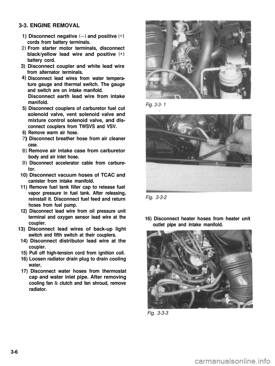
Fig. 3-3- 1
Fig. 3-3-2
16) Disconnect heater hoses from heater unit
outlet pipe and intake manifold.
Fig. 3-3-3
3)
4)
3-6
Page 121 of 962
![SUZUKI GRAND VITARA 1987 Service Repair Manual [Switch vent solenoid]
Provided on top of the float chamber is a switch
vent solenoid which is connected to the ignition
switch through ECM. As the ignition switch is
operated, the solenoid opens and SUZUKI GRAND VITARA 1987 Service Repair Manual [Switch vent solenoid]
Provided on top of the float chamber is a switch
vent solenoid which is connected to the ignition
switch through ECM. As the ignition switch is
operated, the solenoid opens and](/img/20/57437/w960_57437-120.png)
[Switch vent solenoid]
Provided on top of the float chamber is a switch
vent solenoid which is connected to the ignition
switch through ECM. As the ignition switch is
operated, the solenoid opens and closes its valve
so as not to release the fuel vapor in the float
chamber out into the atmosphere.
When the ignition switch is turned to “OFF”
position, the passage connecting the inner vent
passage and the float chamber will close, and the
passage connecting the float chamber and the
canister will open, then the fuel vapor will flow
into the canister.
When the ignition switch is turned to “ON”
position, and engine speed is above 400 r/min,
the passage connecting the float chamber and
the canister will close, and the passage connect-
ing the float chamber and the inner vent passage
will open, then the fuel vapor will flow into the
carburetor bore.
1. Switch vent solenoid
2. Float
3. To canister
4. Inner vent passage
Fig. 4- l-4 Switch vent solenoid
Primary System
[Primary slow system]
The fuel, after passing through the main jet, is
metered by the primary slow jet, then mixed
with the air from the primary slow air No. 2
bleeder. This air/fuel mixture is further blended
with the air from the primary slow air No. 1
bleeder and air supplied through the mixture
control solenoid. Then the air/fuel mixture
passes through the idle down channel and enters
the carburetor bore through the off idle discharge
port and the idle discharge hole.
[Mixture control solenoid valve]
The primary system has the Mixture Control
Solenoid (MCS) Valve. In the MCS, there is a
plunger which makes 16 up and down move-
ments per second by the electrical signals from
the Electronic Control Module (ECM). That is,
when an electrical signal is received by the
solenoid, the plunger will move down and when
no signal is received, the plunger will move up
by the spring force.
When the plunger moves down, the air jet locat-
ed on the upper side of the mixture control
solenoid valve will open as shown in below
figure, allowing the air to flow into the idle
down channel. In this condition, the mixture
will become lean.
On the other hand, when the plunger is pushed
up by the spring, the air jet will close, shutting
off the air flow into the idle down channel. In
this condition, the mixture will become rich.
The up and down movement of the plunger at
the rate of 16 times per second to the signals
from the ECM controls the air/fuel mixture to
the optimum ratio at all times and as a result
helps to improve the emission and engine per-
formances, and fuel economy.
The ECM receives the electrical information
from the oxygen sensor installed to the exhaust
manifold and the engine operating condition
signals from other devices and sends out and
stops the electrical signal to the mixture control
solenoid valve to actuate the plunger up and
down 16 times every second. The ECM is locat-
ed under the glove box of the instrument panel.
4-6
Page 144 of 962

4-2. AIR CLEANER
GENERAL DESCRIPTION
In the air cleaner case, a dry-type air cleaner element is provided for filtering.out dirt and dust from air
being drawn into the engine for combustion.
A damaged element must be replaced with a new one, since it allows dust particles to enter the engine if
used as it is. Such dust particles could cause wear to the engine inner parts and this further results in
decreased output.
Also, the element must be cleaned periodically. Dusty and dirty element causes decrease in output and
increase in fuel consumption. The dusty element even after cleaning should be replaced with a new one.
Fig. 4-2-l
1. Air cleaner case
2. Air cleaner case cap
3. Air cleaner element4. Air cleaner inlet hose
5. Air cleaner outlet hose
6. Warm air hose
7. Carburetor air intake case
8. Check valve
9. Therm0 sensor (valve)10. Air control actuator
MAINTENANCE SERVICES
Air Cleaner Element
[Cleaning]
1) Remove air cleaner outlet hose and case cap.
Fig. 4-2-21. Air cleaner outlet hose2. Air cleaner case cap3. Clamp
4-29
Page 157 of 962
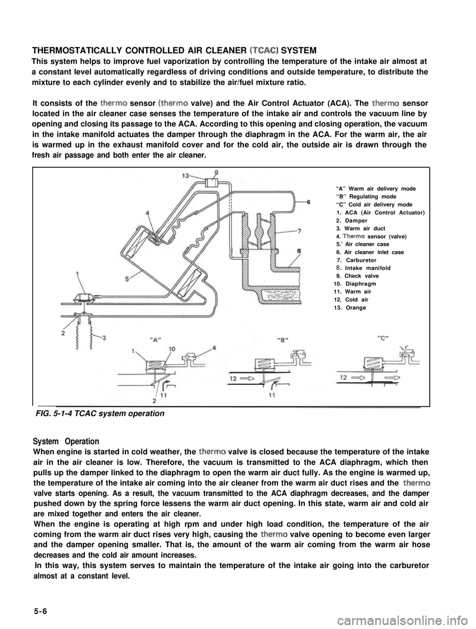
THERMOSTATICALLY CONTROLLED AIR CLEANER (TCAC) SYSTEM
This system helps to improve fuel vaporization by controlling the temperature of the intake air almost at
a constant level automatically regardless of driving conditions and outside temperature, to distribute the
mixture to each cylinder evenly and to stabilize the air/fuel mixture ratio.
It consists of the therm0 sensor (therm0 valve) and the Air Control Actuator (ACA). The therm0 sensor
located in the air cleaner case senses the temperature of the intake air and controls the vacuum line by
opening and closing its passage to the ACA. According to this opening and closing operation, the vacuum
in the intake manifold actuates the damper through the diaphragm in the ACA. For the warm air, the air
is warmed up in the exhaust manifold cover and for the cold air, the outside air is drawn through the
fresh air passage and both enter the air cleaner.
“A” Warm air delivery mode
6“B” Regulating mode
“C” Cold air delivery mode
1. ACA (Air Control Actuator)
2. Damper3. Warm air duct
4. Therm0 sensor (valve)5.’ Air cleaner case66. Air cleaner inlet case
7. Carburetor8. Intake manifold9. Check valve10. Diaphragm11. Warm air
12. Cold air
13. Orange
--
System Operation
When engine is started in cold weather, the therm0 valve is closed because the temperature of the intake
air in the air cleaner is low. Therefore, the vacuum is transmitted to the ACA diaphragm, which then
pulls up the damper linked to the diaphragm to open the warm air duct fully. As the engine is warmed up,
the temperature of the intake air coming into the air cleaner from the warm air duct rises and the therm0
valve starts opening. As a result, the vacuum transmitted to the ACA diaphragm decreases, and the damper
pushed down by the spring force lessens the warm air duct opening. In this state, warm air and cold air
are mixed together and enters the air cleaner.
When the engine is operating at high rpm and under high load condition, the temperature of the air
coming from the warm air duct rises very high, causing the therm0 valve opening to become even larger
and the damper opening smaller. That is, the amount of the warm air coming from the warm air hose
decreases and the cold air amount increases.
In this way, this system serves to maintain the temperature of the intake air going into the carburetor
almost at a constant level.
5-6
FIG. 5-1-4 TCAC system operation
Page 161 of 962
![SUZUKI GRAND VITARA 1987 Service Repair Manual COMPUTER CONTROLLED EMISSION CONTROL SYSTEM
[Feed back system]
A prime purpose of this system is to maintain a controlled air fuel ratio, allowing the catalyst to reduce
oxides of nitrogen, hydrocarbo SUZUKI GRAND VITARA 1987 Service Repair Manual COMPUTER CONTROLLED EMISSION CONTROL SYSTEM
[Feed back system]
A prime purpose of this system is to maintain a controlled air fuel ratio, allowing the catalyst to reduce
oxides of nitrogen, hydrocarbo](/img/20/57437/w960_57437-160.png)
COMPUTER CONTROLLED EMISSION CONTROL SYSTEM
[Feed back system]
A prime purpose of this system is to maintain a controlled air fuel ratio, allowing the catalyst to reduce
oxides of nitrogen, hydrocarbons, carbon monoxide and to improve fuel economy simultaneously.
The electronic control module (ECM) and the oxygen sensor are provided in this system.
The oxygen sensor mounted on the exhaust manifold monitors the exhaust gas air fuel ratio and signals to
the ECM.
The ECM processes the oxygen sensor signal and controls carburetor air fuel ratio by the operation of the
mixture control solenoid in the carburetor.
Thus the signal of the exhaust gas air fuel ratio sensed by the oxygen sensor is fed back to ECM and the
carburetor air fuel ratio is controlled.
[Electronic control module (ECM)]
The ECM controls the fuel cut system, idle-up system, bowl vent system, EGR system and secondary
throttle valve system, as well as the feed back system. The ECM is located under the glove box of the
instrument main panel. Refer to Fig. 5-l -9.
I1
* Engine coolant
temperature
* Engine speed
-Electronic
controlmodule
I I
* Throttle positiont(Micro Switches)
I I I\-
* Fuel cut solenoid valve
-44
* Engine room
- * Vent solenoid valvetempe.rature
* Idle-up actuator (TWSV)* Electric load
* Secondary throttle valve (VSV) , _ ~
r* Mixture control
solenoid valve
* Barometric
pressure
+ ECM supply
voltage
* Gear position
Fig. 5-l-8Computer con trolled emissioncon trot s ys tern
5- 10
Page 162 of 962
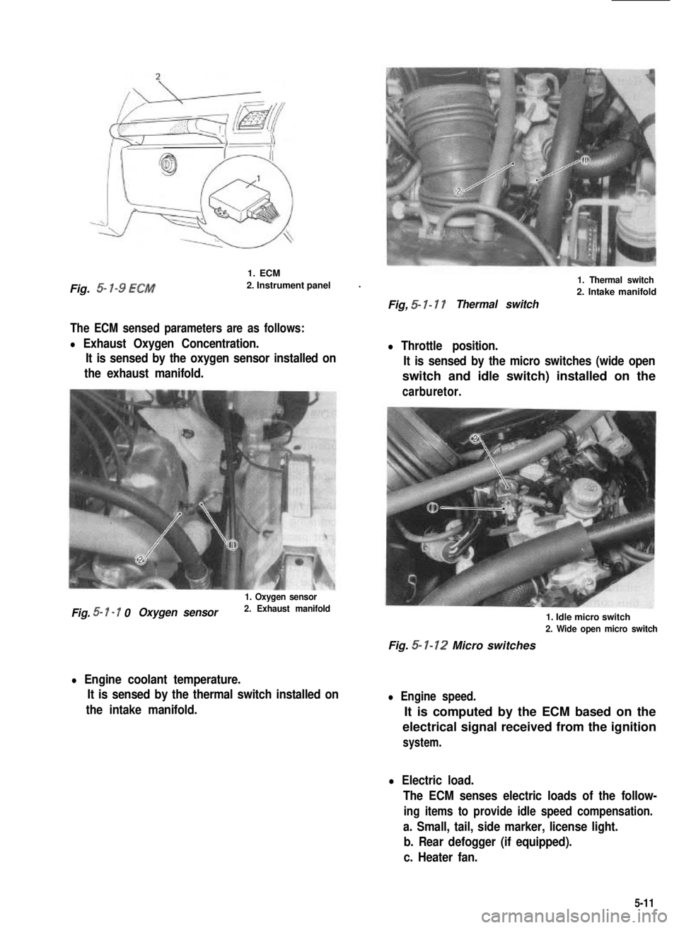
Fig. 5- l-9 ECM
1. ECM
2. Instrument panel.
The ECM sensed parameters are as follows:
l Exhaust Oxygen Concentration.
It is sensed by the oxygen sensor installed on
the exhaust manifold.
1. Oxygen sensor
Fig. 5- I - 7 0Oxygen sensor2. Exhaust manifold
l Engine coolant temperature.
It is sensed by the thermal switch installed on
the intake manifold.
1. Thermal switch
2. Intake manifold
Fig, 5- I- 17Thermal switch
l Throttle position.
It is sensed by the micro switches (wide open
switch and idle switch) installed on the
carburetor.
1. Idle micro switch
2. Wide open micro switch
Fig. 5- 1-12 Micro switches
l Engine speed.
It is computed by the ECM based on the
electrical signal received from the ignition
system.
l Electric load.
The ECM senses electric loads of the follow-
ing items to provide idle speed compensation.
a. Small, tail, side marker, license light.
b. Rear defogger (if equipped).
c. Heater fan.
5-11
Page 170 of 962

TCAC SYSTEM
Checking TCAC System
1) Check vacuum hose for connection, deterio-
ration or damage. Replace as necessary.
4 3
3) Check that when engine is started (and run at
idle speed) under the condition that air
cleaner is cool, valve on warm air side becomes
fully open and one on fresh air inhaling side
is completely closed.
4) If nothing was found faulty in the above step,
connect warm air hose.
1. Air control actuator
2. Therm0 sensor3. Check valve
4. Orange side
Fig, 5-3-3TCA C sys tern
2) With engine at a stop, make sure that the
valve indicated in figure is completely closed
(closing warm air side). This check should be
carried out by putting finger into duct after
removing warm air hose from it.
Fig. 5-3-4Checking TCA C sys tern
If found defective in above step 2) or 3),
inspect following parts according to each
procedure.
[Air control actuator]
1) Disconnect vacuum hose from therm0 sensor.
2) Make sure that damper opens fully when
more than 20 cmHg (7.87 in.Hg) vacuum is
applied to ACA.
Also, make sure that damper is held at the
same position when a constant vacuum is
applied to it.
If damper doesn’t open or close smoothly, or
it isn’t held at the same position, replace ACA.
Fig. 5-3-5 Checking A CA
3
4
1. Air cleaner
2. ACA3. Damper valve
4. Warm air5. Fresh air
[Thermo sensor]
1) Remove air cleaner case cap.
2) Disconnect two vacuum hoses from therm0
sensor.
I) Measure the temperature around therm0
sensor.
.) Close a nozzle with finger and then blow air
into nozzle. If measured temperature is above
40°C (104” F), air should come out of therm0
sensor valve (valve is open) as shown in Fig.
5-3-6.
If the temperature is below 25°C (77”F), air
should not come out (valve is closed).
Replace defective parts.5-19