service SUZUKI GRAND VITARA 1987 Service Repair Manual
[x] Cancel search | Manufacturer: SUZUKI, Model Year: 1987, Model line: GRAND VITARA, Model: SUZUKI GRAND VITARA 1987Pages: 962, PDF Size: 27.87 MB
Page 1 of 962

FOREWORD
This manual contains procedures for diagnosis, maintenance adjustments, \
service operations,
replacement of components (Service) and for disassembly and assembly o\
f major compo-
nents.
The contents are classified into sections each of which is given a secti\
on number as indicated
in the Table of Contents on next page. And on the first page of each ind\
ividual section is an
index of that section.
This manual should be kept in a handy place for ready reference of the s\
ervice work. Strict
observance of the so specified items will enable one to obtain the full \
performance of the
vehicle.
When replacing parts or servicing by disassembling, it is recommended to\
use SUZUKI
genuine parts, tools and service materials (lubricants, sealants, etc.)\
as specified in each
description.
All information, illustrations and specifications contained in this lite\
rature are based on the
latest product information available at the time of publication approval\
. The right is reserved
to make changes at any time without notice. And used as the main subject\
of description is
the vehicle of standard specifications among others. Therefore, note tha\
t illustrations and
photos may differ from the vehicle being actually serviced.
IMPORTANT:
It is important to note that, during any vehicle maintenance procedures,\
replacement
fasteners must have the same measurements as those removed.
Mismatched or incorrect fasteners can result in vehicle damage or malfun\
ction, or possible
personal injury.
Therefore, fasteners removed from the vehicle should be saved for re-use\
whenever possible.
Where the fasteners are not satisfactory for reuse, care should be taken\
to select a replace-
ment that matches the original.
Additional information concerning this subject will be found in the sect\
ion 0 (METRIC
INFORMATION).
This service manual is applicable to vehicles of and after the following\
body number.
Effective body No.:
J4235001
SUZUKI MOTOR
TECHNICAL DEPARTMENT
AUTOMOBILE SERVICE DIVISION
0 COPYRIGHT SUZUKI MOTOR CO., LTD. 1987
CO LTD
JS3JC51C J4235001
JS3JC51V J4150001
JS4JC51C J4235001
JS4JC51V 54150001
Page 2 of 962
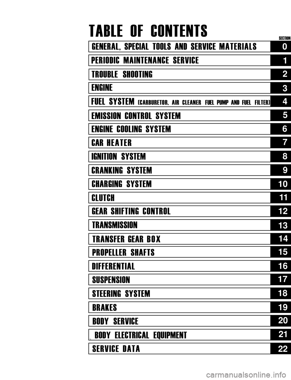
TABLE OF CONTENTS
GENERAL, SPECIAL TOOLS AND SERVICE MATERIALS
PERIODIC MAINTENANCE SERVICE
TROUBLE SHOOTING
ENGINE
FUEL SYSTEM (CARBURETOR, AIR CLEANER FUEL PUMP AND FUEL FILTER)
EMISSION CONTROL SYSTEM
ENGINE COOLING SYSTEM
CAR HEATER
IGNITION SYSTEM
CRANKING SYSTEM
CHARGING SYSTEM
CLUTCH
GEAR SHIFTING CONTROL
TRANSMISSION
TRANSFER GEAR BOX
PROPELLER SHAFTS
DIFFERENTIAL
SUSPENSION
STEERING SYSTEM
BRAKES
BODY SERVICE
,i BODY ELECTRICAL EQUIPMENT
SERVICE DATA
0
1
2
5
6
7
8
9
10
1111
12
13
14
15
16
17
18
19
20
21
22
4
3
SECTION
Page 3 of 962
SECTION 0
GENERAL, SPECIAL TOOLS AND
SERVICE MATERIALS
CONTENTS
0-1. IDENTIFICATION NUMBER . . . . . . . . . . . . . . . . . . . . . . . . . . . . . . . . . O-1
0-2. STANDARD SHOP PRACTICES . . . . . . . . . . . . . . . . . . . . . . . . . . . . . . . O-2
0-3.SPECIAL TOOLS.. . . . . . . . . . . . 1.. . . . . . . . . . . . . . . . . . . . . . . . . . . . .
0-4.REQUIRED SERVICE MATERIALS . . . . . . . . . . . . . . . . . . . . . s . . . . . O-9
METRIC INFORMATION . . . . . . . . . . . . . . . . . . . . . , . . . . . . . . . . . . . O-12
O-l. IDENTIFICATION NUMBER
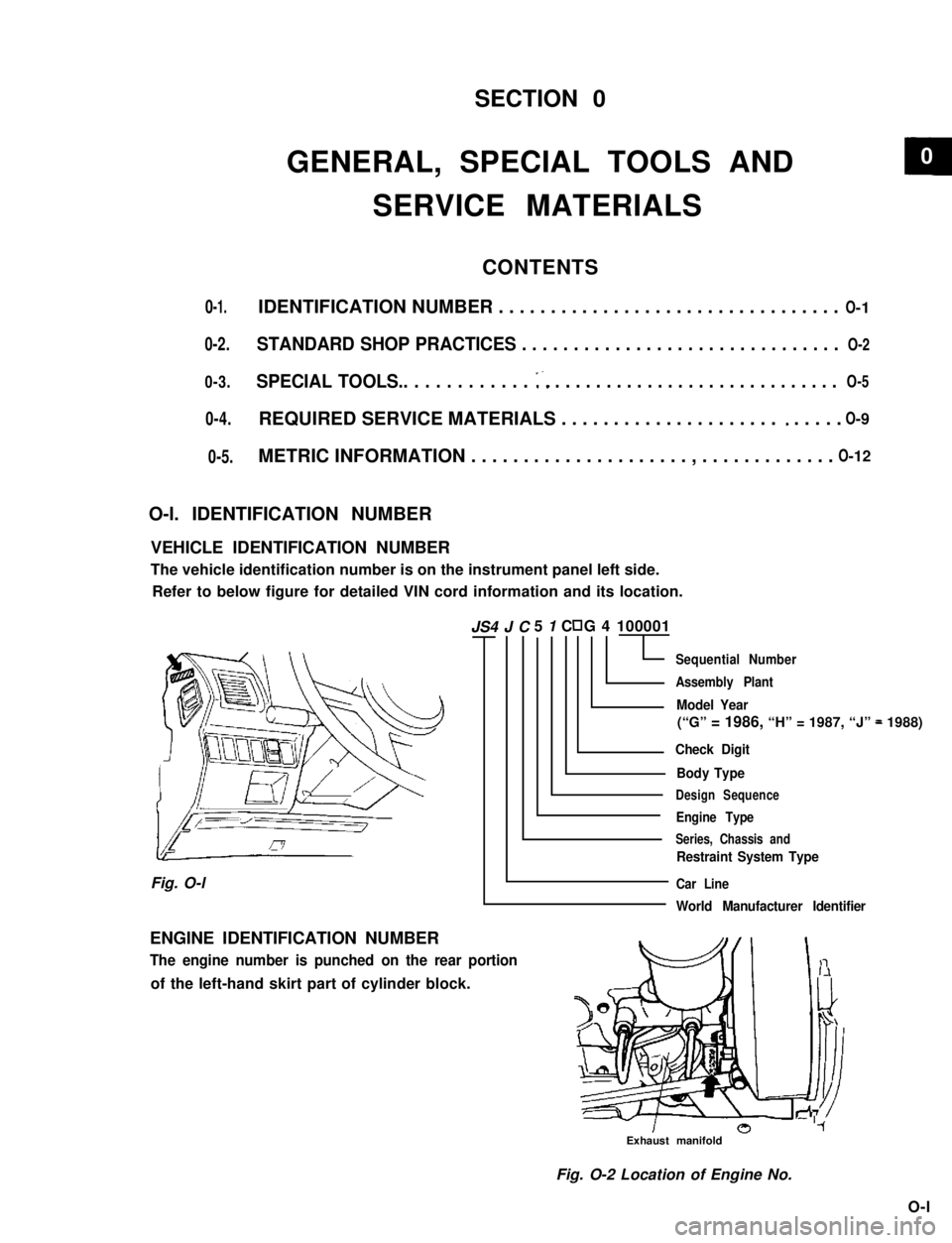
VEHICLE IDENTIFICATION NUMBER
The vehicle identification number is on the instrument panel left side.
Refer to below figure for detailed VIN cord information and its location.
5 1 C G 4 100001
Sequential Number
Assembly Plant
Model Year
(“G” = 1986, “H” = 1987, “J” = 1988)
Check Digit
Body Type
Design Sequence
Engine Type
Series, Chassis and
Restraint System Type
Car Line
World Manufacturer Identifier
Fig. O-l
ENGINE IDENTIFICATION NUMBER
The engine number is punched on the rear portion
of the left-hand skirt part of cylinder block.
Exhaust manifold
Fig. O-2 Location of Engine No.
O-l
JS4 J C
0-5.
O- 5
0
Page 4 of 962
O-2. STANDARD SHOP PRACTICES
1. Protect painted surfaces of the body, and
avoid staining or tearing seats. When working
on fenders and seats, be sure to cover them
up with sheets.
2. Disconnect negative terminal connection of
the battery when working on any electrical
part or component. This is necessary for
avoiding electrical shocks and short-circuit-
ing, and is very simple to accomplish: merely
loosen wing nut on negative terminal and
separate cable from terminal post.
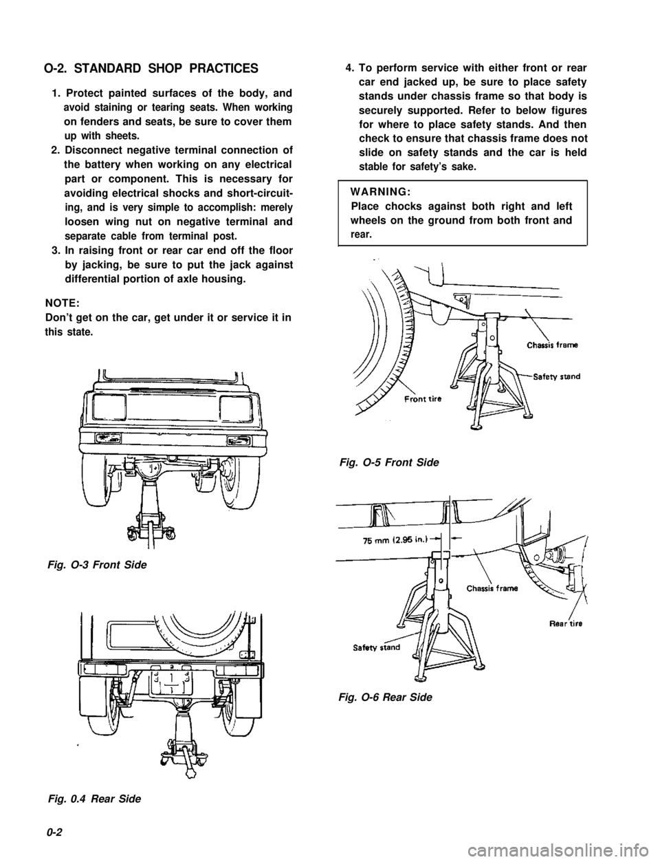
3. In raising front or rear car end off the floor
by jacking, be sure to put the jack against
differential portion of axle housing.
NOTE:
Don’t get on the car, get under it or service it in
this state.
Fig. O-3 Front Side
4. To perform service with either front or rear
car end jacked up, be sure to place safety
stands under chassis frame so that body is
securely supported. Refer to below figures
for where to place safety stands. And then
check to ensure that chassis frame does not
slide on safety stands and the car is held
stable for safety’s sake.
WARNING:
Place chocks against both right and left
wheels on the ground from both front and
rear.
Fig. O-5 Front Side
&
Fig. O-6 Rear Side
Fig. 0.4 Rear Side
0-2
Page 17 of 962

SECTION 1
PERIODIC MAINTENANCE SERVICE
CONTENTS
1-1. MAINTENANCE SCHEDULE..................................
1-2.ENGINE AND EMISSION CONTROL...........................1-5
1-3.CHASSIS AND BODY......................................1-17
1
1-2
1-1
Page 25 of 962

CAUTION:
When changing engine coolant, use mixture
of 56% water and 50% GOLDEN CRUISER
1200for the market where ambient tem-
perature falls lower than -16°C (3°F) in
winter and mixture of 70% water and
30% GOLDEN CRUISER 1200for the
market where ambient temperature doesn’t
fall lower than -16°C (3” F).
Even in a market where no freezing tempe-
rature is anticipated, mixture of 70% water
and 30% GOLDEN CRUISER 1200
should be used for the purpose of corro-
sion protection and lubrication.
7. EXHAUST PIPES AND MOUNTINGS
INSPECTION
1.Drain plug
1. Reservoir tank cap2. Reservoir tank
3. Arrow marks
5) Fill radiator with specified amount of coolant,
and run engine for 2 or 3 minutes at idle.
This drives out any air which may still be
trappedwithincoolingsystem.STOP
ENGINE. Add coolant as necessary until
coolant level reaches the filler throat of
radiator. Reinstall radiator cap.
6) Add coolant to reservoir tank so that the level
aligns with Full mark. Then, reinstall cap
aligning the arrow marks on the tank and cap.
r.
COOLANT CAPACITY
Engine, radiator and4.2 liters
heater(8.9/7.4 US/Imp pt.)
Reservoir tank0.6 liters
(1.3/1.1 US/Imp pt.)
ITotal4.8 liters
(10.1/8.4US/lmp pt.)
WARNING:
To avoid danger of being burned, do not
touch exhaust system when system is hot.
Any service on exhaust system should be
performed when system is cool.
When carrying out periodic maintenance, or the
car is raised for other service, check exhaust
system as follows:
l Check rubber mountings for damage, deterio-
ration, and out of position.
l Check exhaust system for leakage, loose
connections, dents, and damages.
If bolts or nuts are loose, tighten them to
specification. Refer to below chart for torque
specification.
l Check nearby body areas for damaged, miss-
ing, or mispositioned parts, open seams,
holes, loose connections or’ other defects
which could permit exhaust fumes to seep
into the car.
l Make sure that exhaust system components
have enough clearance from the underbody to
avoid overheating and possible damage to the
floor carpet.
l Any defects should be fixed at once.
IBolts and nutTightening torqueI
40-80 N-m
Exhaustpipebolts4.0-6.0 kg-m
29.0-43.0 lb-ft
Muffler nuts
18 - 28 N-m
1.8 - 2.8 kg-m
13.5 - 20.0 lb-ft
Replace center pipe rubber mounting and muffler
rubber mountings with new ones periodically.
l-9
Page 26 of 962
8. PCV VALVE REPLACEMENT
1) Disconnect crankcase ventilation hose from
PCV valve.
2) Remove PCV valve from intake manifold.
3) Wind sealing tape on thread of the new valve
and install it securely.
Tightenlng torque
for PCV valve
15-25 N.m
1.5-2.5 kg-m,
11 .O-18.0 lb-ft
4) Install hose and clamp it securely.
9. OXYGEN SENSOR REPLACEMENT
[Canadian specification vehicle]
When the odometer indicates 50,000 and 100,000
miles, replace oxygen sensor as follows.
CAUTION:
To avoid the danger of being burned, do
not touch the exhaust system when the
system is hot. This work should be perform-
ed when the system is cool.
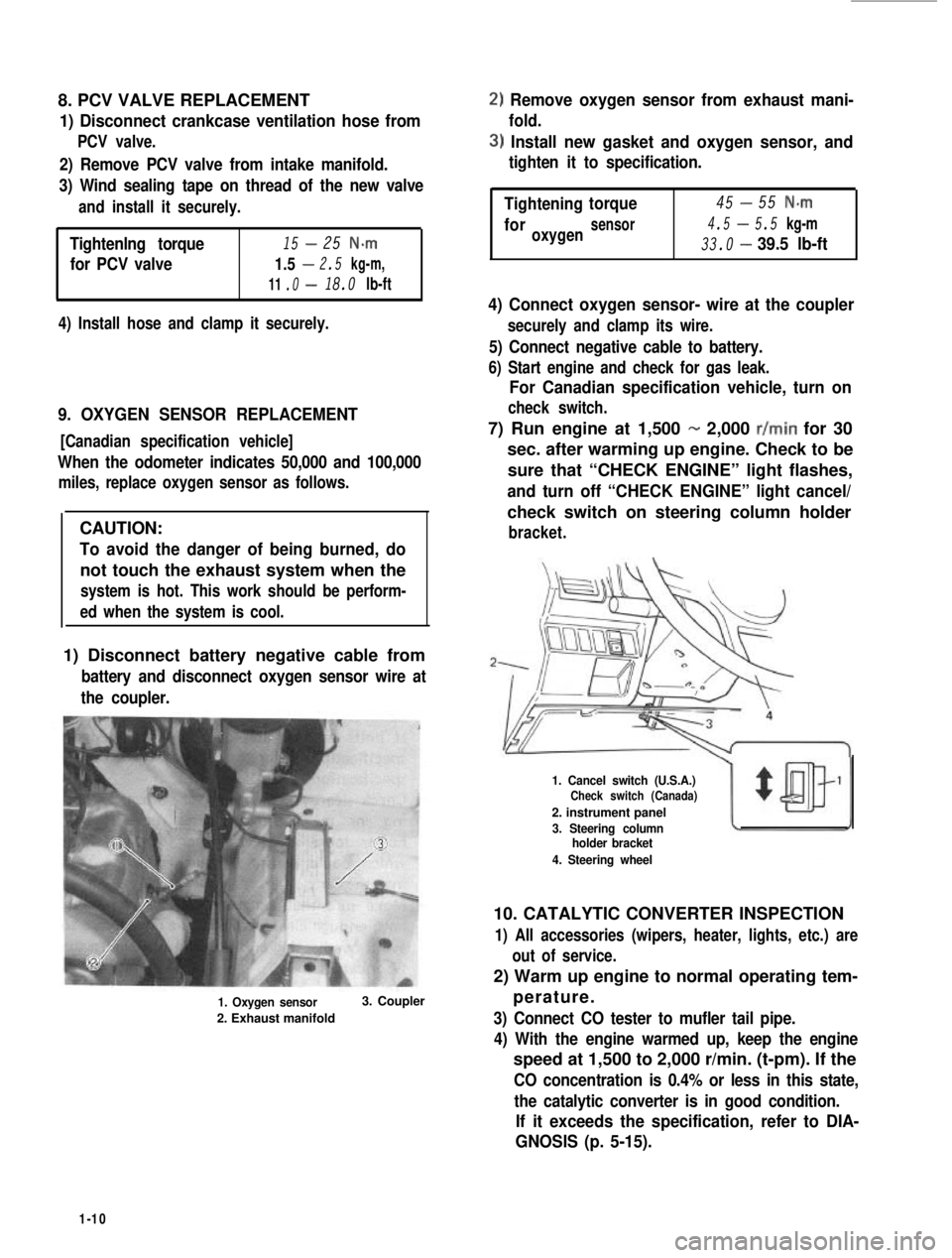
1) Disconnect battery negative cable from
battery and disconnect oxygen sensor wire at
the coupler.
1. Oxygen sensor
2. Exhaust manifold
3. Coupler
2) Remove oxygen sensor from exhaust mani-
fold.
3) Install new gasket and oxygen sensor, and
tighten it to specification.
-Tightening45torque55 N-m
4.5-foroxygensensor5.5 kg-m
33.0-39.5 lb-ft
4) Connect oxygen sensor- wire at the coupler
securely and clamp its wire.
5) Connect negative cable to battery.
6) Start engine and check for gas leak.
For Canadian specification vehicle, turn on
check switch.
7) Run engine at 1,500 - 2,000 r/min for 30
sec. after warming up engine. Check to be
sure that “CHECK ENGINE” light flashes,
and turn off “CHECK ENGINE” light cancel/
check switch on steering column holder
bracket.
1. Cancel switch (U.S.A.)Check switch (Canada)
2. instrument panel
3. Steering columnholder bracket
4. Steering wheel
10. CATALYTIC CONVERTER INSPECTION
1) All accessories (wipers, heater, lights, etc.) are
out of service.
2) Warm up engine to normal operating tem-
perature.
3) Connect CO tester to mufler tail pipe.
4) With the engine warmed up, keep the engine
speed at 1,500 to 2,000 r/min. (t-pm). If the
CO concentration is 0.4% or less in this state,
the catalytic converter is in good condition.
If it exceeds the specification, refer to DIA-
GNOSIS (p. 5-15).
1-10
Page 31 of 962

1) Replace fuel hoses (pipe to fuel pump, pipe to
fuel filter and breather hose) in fuel feed and
return lines with new ones.
2) Remove fuel tank.
3) Replace return hose (tank to return pipe)
with new one.
4) Clamp hoses securely.
5) Install fuel tank referring to p. 4-35.
6) After installation, start engine and check it
for leaks.
27. IDLE SPEED INSPECTION
NOTE:
Before starting engine, place transmission gear
shift lever in “Neutral”, and set parking brake
and block drive wheels.
1) Warm up engine to normal operating tempe-
rature.
2) Check to ensure that idle speed is within
750 - 850 r/min (rpm).
3) If idle speed is not within specified range,
adjust idle speed. Refer to MAINTENANCE
SERVICE (p. 4-26) for procedures to check
and adjust idle speed.
28. IDLE MIXTURE INSPECTION
1) Warm up engine to normal operating tem-
perature.
2) Remove seal rubber of duty check coupler
and connect positive terminal of duty meter
to “Blue/Red” wire and negative terminal to
“Black/Green” wire.
1
1. Duty check coupler
2. Air intake case
3) Set tachometer.
4) Run engine at 1,500 - 2,000 r/min for 30
seconds and bring it to idle speed.
5) Check duty at specified idle speed. If it is out
of specification,adjust it to specification
according to following adjustment procedure.
Specified Duty10-50
at 750 - 850 r/min.I
After inspection, install seal rubber to duty
check coupler.
Idle mixture adjustment procedure is as follows:
1) Remove carburetor from intake manifold
following normal service procedure to gain
access to mixture adjusting screw pin covering
mixture adjusting screw.
2) Drive out mixture adjusting screw pin using
about 4.5 mm (0.18 in) thick iron rod as
shown below.
1-15
Page 32 of 962
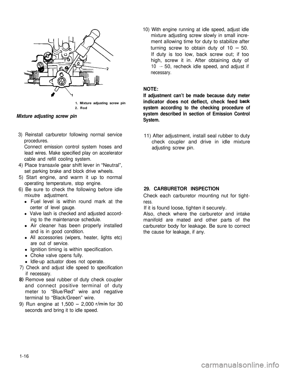
1. Mixture adjusting screw pin
2. Rod
Mixture adjusting screw pin
10) With engine running at idle speed, adjust idle
mixture adjusting screw slowly in small incre-
ment allowing time for duty to stabilize after
turning screw to obtain duty of 10 - 50.
If duty is too low, back screw out; if too
high, screw it in. After obtaining duty of
10- 50, recheck idle speed, and adjust if
necessary.
NOTE:
If adjustment can’t be made because duty meter
indicator does not deflect, check feed baCk
system according to the checking procedure of
system described in section of Emission Control
System.
3) Reinstall carburetor following normal service
procedures.
Connect emission control system hoses and
lead wires. Make specified play on accelerator
cable and refill cooling system.
11) After adjustment, install seal rubber to duty
check coupler and drive in idle mixture
adjusting screw pin.
4) Place transaxle gear shift lever in “Neutral”,
set parking brake and block drive wheels.
5) Start engine, and warm it up to normal
operating temperature, stop engine.
6) Be sure to check the following before idle
mixutre adjustment.
l Fuel level is within round mark at the
center of level gauge.
l Valve lash is checked and adjusted accord-
ing to the maintenance schedule.
l Air cleaner has been properly installed
and is in good condition.
l All accessories (wipers, heater, lights etc)
are out of service.
29. CARBURETOR INSPECTION
Check each carburetor mounting nut for tight-
ness.
If it is found loose, tighten it securely.
Also, check where the carburetor and intake
manifold are mated and other parts of the
carburetor body for leakage. Be sure to correct
the cause for leakage, if any.
l Ignition timing is within specification.
l Choke valve opens fully.
l Idle-up actuator does not operate.
7) Check and adjust idle speed to specification
if necessary.
8) Remove seal rubber of duty check coupler
and connect positive terminal of duty
meter to“Blue/Red” wire and negative
terminal to “Black/Green” wire.
9) Run engine at 1,500 - 2,000 r/min for 30
seconds and bring it to idle speed.
1-16
Page 33 of 962
1-3. CHASSIS AND BODY
30. CLUTCH PEDAL INSPECTION
1) Check clutch pedal height. It should be the
same as brake pedal height.
2) Check clutch pedal free travel.
Clutch pedal free travel20 - 30 mm
(0.8 - 1.1 in.)
For the details of the above steps 1) and 2),
refer to MAINTENANCE SERVICE (p. 11-8) of
SECTION 11.
31. BRAKE DISCS, PADS, BRAKE DRUMS
AND SHOES INSPECTION
Brake Discs and Pads
I) Remove wheel and caliper but don’t discon-
nect brake hose from caliper.
2) Check front disc brake pads and discs for
excessivewear,damageand deflection.
Replace parts as necessary. For the details,
refer to p. 19-I 6 and 19-I 7 of SECT ION 19.
Be sure to torque caliper guide pins to specifi-
cation for reinstallation.
Brake Drums and Shoes
I) Remove wheel and brake drum.
2) Check rear brake drums and brake linings for
excessive wear and damage, while wheels and
drums are removed. Also check wheel cylin-
ders for leaks, at the same time. Replace
these parts as necessary.
For the details, refer to p. 19-21 and p. 19-
22 of SECTION 19.
32. BRAKE HOSES AND PIPES INSPECTION
Check brake hoses and pipes for proper hook-
up, leaks, cracks, chafing and other damage.
Replace any of these parts as necessary.
CAUTION:
After replacing any brake pipe or hose, be
sure to carry out air purge operation.
33. BRAKE FLUID INSPECTION AND
CHANGE
[INSPECTION]
1) Check around master cylinder and reservoir
for fluid leakage.
If found leaky, correct.
2) Check fluid level
If fluid level is lower than the minimum level
of reservoir, refilling is necessary. Fill reservoir
with specified brake fluids.
Brake fluid Speifi;t3ons
For the details, refer to MAINTENANCE
SERVICE (p. 19-42) of SECTION 19.
CAUTION:
Since the brake system of this car is factory-
filled with glycol-base brake fluid, do not
use or mix different type of fluid when
refilling the system; otherwise serious
damage will occur. Do not use old or used
brake fluid, or one taken from unsealed
container.
[CHANGE]
1) Change brake fluid. As fluid change procedure,
drain existing fluid from brake system com-
pletely, fill the system with above recom-
mended fluid and carry out air purge opera-
tion.
For description of air purge, refer to p. 19-46
and 19-47 of SECTION 19.
34. BRAKE PEDAL INSPECTION
Check brake pedal travel.
For -checking procedure, refer to PEDAL TRA-
VEL CHECK (p. 19-43) of SECTION 19.
35. BRAKE LEVER AND CABLE
INSPECTION
Parking Brake Lever
I) Check tooth tip of each notch for damage or
wear. If any damage or wear is found, replace
parking lever.
2) Check parking brake lever for proper opera-
tion and stroke, and adjust it if necessary.
For checking and adjusting procedures,
refer to PARKING BRAKE INSPECTION
AND ADJUSTMENT (p. 19-44) of SECTION
19.
1-17