Pcm SUZUKI GRAND VITARA 1999 2.G Owners Manual
[x] Cancel search | Manufacturer: SUZUKI, Model Year: 1999, Model line: GRAND VITARA, Model: SUZUKI GRAND VITARA 1999 2.GPages: 656, PDF Size: 14.31 MB
Page 39 of 656
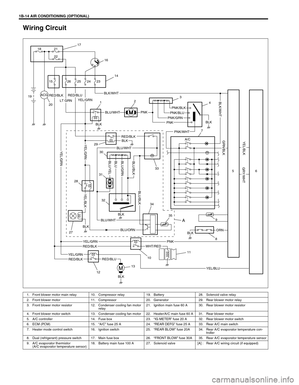
1B-14 AIR CONDITIONING (OPTIONAL)
Wiring Circuit
ACG
LT GRN
PNK
PNK
BLKORN
BLK
YEL/GRNRED/BLKBLK/WHT
BLU/WHTPNK/BLK
PNK/GRN
RED/BLK
WHT/RED
YEL/GRN
YEL/BLU
A/C
RED/BLU
RED/BLU
RED/BLKBLK
BLU/ORN
BLU/WHT
BLU/WHT
PNK
PNK/BLU
BLK
PNK/WHT
YEL/BLK
GRY/WHT
GRN/BLK
BLK/WHT
RED/BLK
YEL/GRN
BLK
BLK
BLK
YEL/BLK
YEL/GRN
YEL/GRNBLU/GRN
BLU/YELBLUBLU/BLK
BLU/BLK
17
21
22 18
16
15
19
2026 25 24 23
14
12
29
3
4
7
33 30
31
32
28
27
1213
10
11
35 349
856
A
1. Front blower motor main relay 10. Compressor relay 19. Battery 28. Solenoid valve relay
2. Front blower motor 11. Compressor 20. Generator 29. Rear blower motor relay
3. Front blower motor resistor 12. Condenser cooling fan motor
relay21. Ignition main fuse 60 A 30. Rear blower motor resistor
4. Front blower motor switch 13. Condenser cooling fan motor 22. Heater/A/C main fuse 60 A 31. Rear blower motor
5. A/C controller 14. Fuse box 23.“IG METER” fuse 20 A 32. Rear blower motor switch
6. ECM (PCM) 15.“A/C” fuse 25 A 24.“REAR DEFG” fuse 25 A 33. Rear A/C main switch
7. Heater mode control switch 16. Ignition switch 25.“REAR BLOW” fuse 20A 34. Rear A/C evaporator temperature con-
troller
8. Dual (refrigerant) pressure switch 17. Main fuse box 26.“FRONT BLOW” fuse 30A 35. Rear A/C evaporator temperature sensor
9. A/C evaporator thermistor
(A/C evaporator temperature sensor)18. Battery main fuse 100 A 27. Solenoid valve [A] : Rear A/C wiring circuit (if equipped)
Page 139 of 656
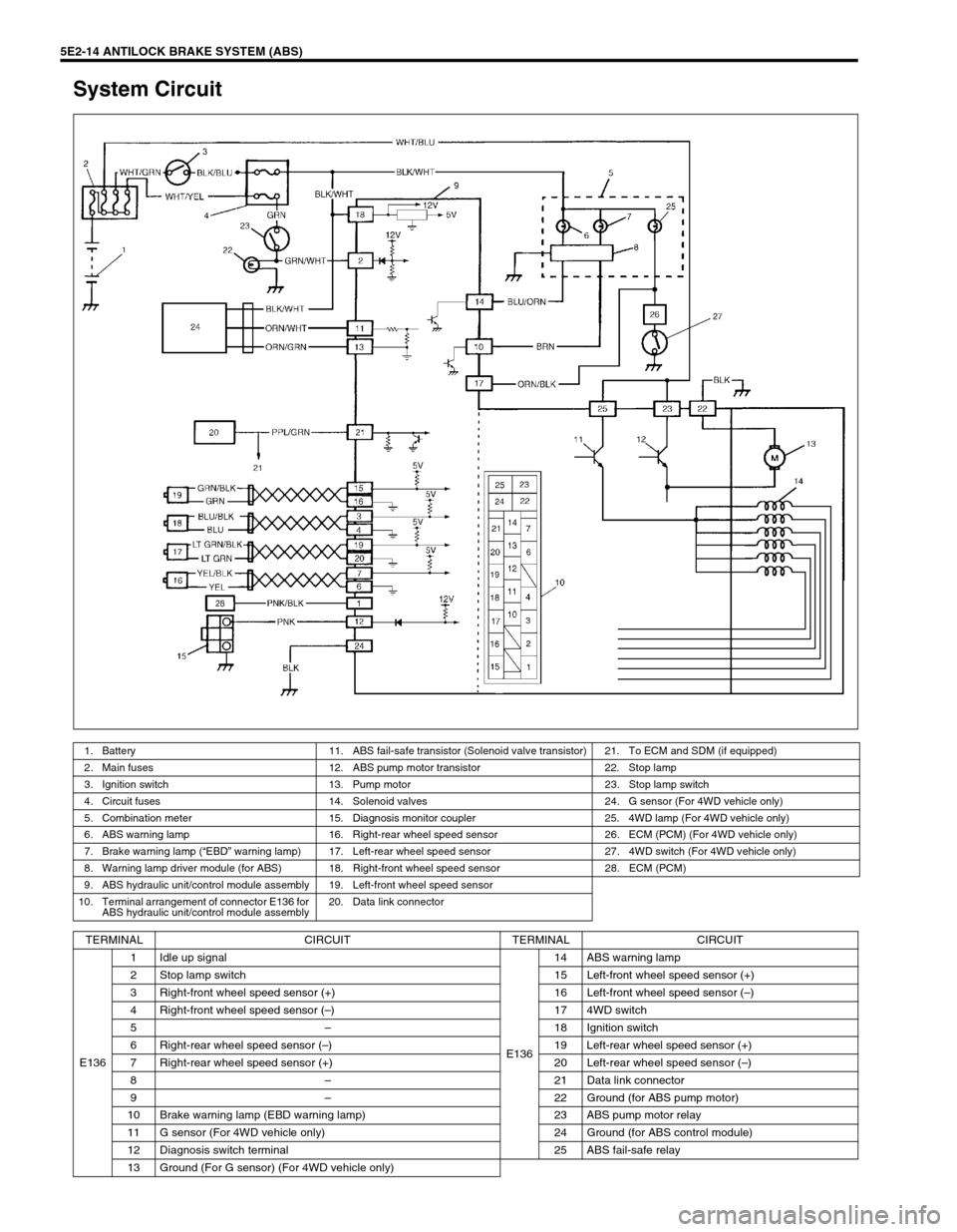
5E2-14 ANTILOCK BRAKE SYSTEM (ABS)
System Circuit
1. Battery 11. ABS fail-safe transistor (Solenoid valve transistor) 21. To ECM and SDM (if equipped)
2. Main fuses 12. ABS pump motor transistor 22. Stop lamp
3. Ignition switch 13. Pump motor 23. Stop lamp switch
4. Circuit fuses 14. Solenoid valves 24. G sensor (For 4WD vehicle only)
5. Combination meter 15. Diagnosis monitor coupler 25. 4WD lamp (For 4WD vehicle only)
6. ABS warning lamp 16. Right-rear wheel speed sensor 26. ECM (PCM) (For 4WD vehicle only)
7. Brake warning lamp (“EBD” warning lamp) 17. Left-rear wheel speed sensor 27. 4WD switch (For 4WD vehicle only)
8. Warning lamp driver module (for ABS) 18. Right-front wheel speed sensor 28. ECM (PCM)
9. ABS hydraulic unit/control module assembly 19. Left-front wheel speed sensor
10. Terminal arrangement of connector E136 for
ABS hydraulic unit/control module assembly20. Data link connector
TERMINAL CIRCUIT TERMINAL CIRCUIT
E1361 Idle up signal
E13614 ABS warning lamp
2 Stop lamp switch 15 Left-front wheel speed sensor (+)
3 Right-front wheel speed sensor (+) 16 Left-front wheel speed sensor (–)
4 Right-front wheel speed sensor (–) 17 4WD switch
5–18 Ignition switch
6 Right-rear wheel speed sensor (–) 19 Left-rear wheel speed sensor (+)
7 Right-rear wheel speed sensor (+) 20 Left-rear wheel speed sensor (–)
8–21 Data link connector
9–22 Ground (for ABS pump motor)
10 Brake warning lamp (EBD warning lamp) 23 ABS pump motor relay
11 G sensor (For 4WD vehicle only) 24 Ground (for ABS control module)
12 Diagnosis switch terminal 25 ABS fail-safe relay
13 Ground (For G sensor) (For 4WD vehicle only)
Page 145 of 656
5E2-20 ANTILOCK BRAKE SYSTEM (ABS)
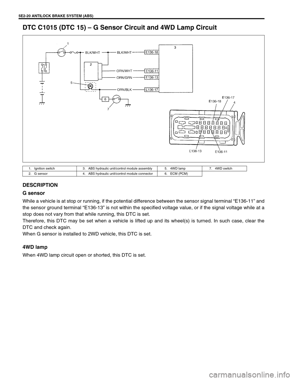
DTC C1015 (DTC 15) – G Sensor Circuit and 4WD Lamp Circuit
DESCRIPTION
G sensor
While a vehicle is at stop or running, if the potential difference between the sensor signal terminal “E136-11” and
the sensor ground terminal “E136-13” is not within the specified voltage value, or if the signal voltage while at a
stop does not vary from that while running, this DTC is set.
Therefore, this DTC may be set when a vehicle is lifted up and its wheel(s) is turned. In such case, clear the
DTC and check again.
When G sensor is installed to 2WD vehicle, this DTC is set.
4WD lamp
When 4WD lamp circuit open or shorted, this DTC is set.
1. Ignition switch 3. ABS hydraulic unit/control module assembly 5. 4WD lamp 7. 4WD switch
2. G sensor 4. ABS hydraulic unit/control module connector 6. ECM (PCM)
Page 146 of 656
ANTILOCK BRAKE SYSTEM (ABS) 5E2-21
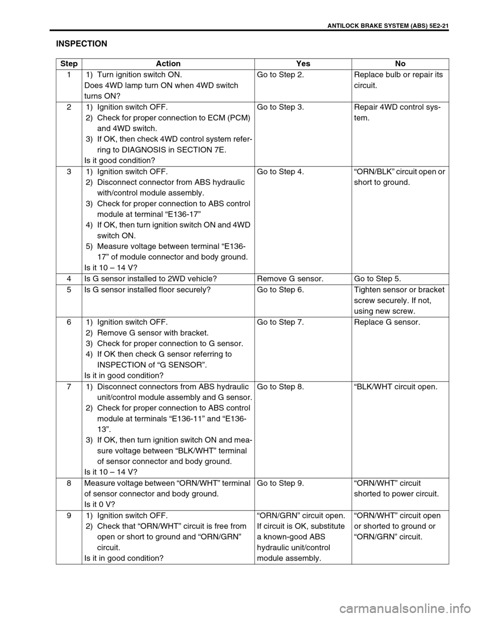
INSPECTION
Step Action Yes No
1 1) Turn ignition switch ON.
Does 4WD lamp turn ON when 4WD switch
turns ON?Go to Step 2. Replace bulb or repair its
circuit.
2 1) Ignition switch OFF.
2) Check for proper connection to ECM (PCM)
and 4WD switch.
3) If OK, then check 4WD control system refer-
ring to DIAGNOSIS in SECTION 7E.
Is it good condition?Go to Step 3. Repair 4WD control sys-
tem.
3 1) Ignition switch OFF.
2) Disconnect connector from ABS hydraulic
with/control module assembly.
3) Check for proper connection to ABS control
module at terminal “E136-17”
4) If OK, then turn ignition switch ON and 4WD
switch ON.
5) Measure voltage between terminal “E136-
17” of module connector and body ground.
Is it 10 – 14 V?Go to Step 4.“ORN/BLK” circuit open or
short to ground.
4 Is G sensor installed to 2WD vehicle? Remove G sensor. Go to Step 5.
5 Is G sensor installed floor securely? Go to Step 6. Tighten sensor or bracket
screw securely. If not,
using new screw.
6 1) Ignition switch OFF.
2) Remove G sensor with bracket.
3) Check for proper connection to G sensor.
4) If OK then check G sensor referring to
INSPECTION of “G SENSOR”.
Is it in good condition?Go to Step 7. Replace G sensor.
7 1) Disconnect connectors from ABS hydraulic
unit/control module assembly and G sensor.
2) Check for proper connection to ABS control
module at terminals “E136-11” and “E136-
13”.
3) If OK, then turn ignition switch ON and mea-
sure voltage between “BLK/WHT” terminal
of sensor connector and body ground.
Is it 10 – 14 V?Go to Step 8.“BLK/WHT circuit open.
8 Measure voltage between “ORN/WHT” terminal
of sensor connector and body ground.
Is it 0 V?Go to Step 9.“ORN/WHT” circuit
shorted to power circuit.
9 1) Ignition switch OFF.
2) Check that “ORN/WHT” circuit is free from
open or short to ground and “ORN/GRN”
circuit.
Is it in good condition?“ORN/GRN” circuit open.
If circuit is OK, substitute
a known-good ABS
hydraulic unit/control
module assembly.“ORN/WHT” circuit open
or shorted to ground or
“ORN/GRN” circuit.
Page 160 of 656
ANTILOCK BRAKE SYSTEM (ABS) 5E2-35
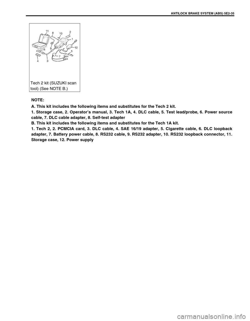
Tech 2 kit (SUZUKI scan
tool) (See NOTE B.)
NOTE:
A. This kit includes the following items and substitutes for the Tech 2 kit.
1. Storage case, 2. Operator’s manual, 3. Tech 1A, 4. DLC cable, 5. Test lead/probe, 6. Power source
cable, 7. DLC cable adapter, 8. Self-test adapter
B. This kit includes the following items and substitutes for the Tech 1A kit.
1. Tech 2, 2. PCMCIA card, 3. DLC cable, 4. SAE 16/19 adapter, 5. Cigarette cable, 6. DLC loopback
adapter, 7. Battery power cable, 8. RS232 cable, 9. RS232 adapter, 10. RS232 loopback connector, 11.
Storage case, 12. Power supply
Page 162 of 656
ENGINE GENERAL INFORMATION AND DIAGNOSIS (H27 ENGINE) 6-1-1
6-1
SECTION 6-1
ENGINE GENERAL INFORMATION AND
DIAGNOSIS (H27 ENGINE)
CONTENTS
General Information ...................................... 6-1-3
Statement of Cleanliness and Care ............ 6-1-3
General Information on Engine Service ...... 6-1-3
Precaution on Fuel System Service ............ 6-1-4
Fuel Pressure Relief Procedure .................. 6-1-5
Fuel Leakage Check Procedure .................. 6-1-5
Engine Diagnosis .......................................... 6-1-6
General Description .................................... 6-1-6
On-Board Diagnostic System (Vehicle
without Monitor Connector) ......................... 6-1-6
On-Board Diagnostic System (Vehicle with
Monitor Connector) ..................................... 6-1-9
Precaution in Diagnosing Trouble ............. 6-1-10
Engine Diagnostic Flow Table ................... 6-1-11
Malfunction Indicator Lamp (MIL) Check... 6-1-16
Diagnostic Trouble Code (DTC) Check ..... 6-1-16
Diagnostic Trouble Code (DTC) Clearance 6-1-17
Diagnostic Trouble Code (DTC) Table ...... 6-1-18For A/T system (Refer to Section 7B1
for diagnosis)......................................... 6-1-21
For immobilizer control system (Refer to
Section 8G for diagnosis) ...................... 6-1-22
Fail-Safe Table.......................................... 6-1-23
Scan Tool Data ......................................... 6-1-24
Scan tool data definitions ...................... 6-1-27
Engine Diagnosis Table ............................ 6-1-31
Inspection of PCM (ECM) and its Circuits. 6-1-36
Table A-1 Malfunction Indicator Lamp
Circuit Check – Lamp Does Not Come
“ON” or Dims at Ignition Switch ON
(But Engine at Stop).................................. 6-1-43
Table A-2 Malfunction Indicator Lamp
Circuit Check – Lamp Remains “ON” after
Engine Starts ............................................ 6-1-44
Table A-3 Malfunction Indicator Lamp
Check – MIL Flashes at Ignition Switch
ON (Vehicle with Monitor Connector) ....... 6-1-45 WARNING:
For vehicles equipped with Supplemental Restraint (Air Bag) System:
Service on and around the air bag system components or wiring must be performed only by an
authorized SUZUKI dealer. Refer to “Air Bag System Components and Wiring Location View” under
“General Description” in air bag system section in order to confirm whether you are performing ser-
vice on or near the air bag system components or wiring. Please observe all WARNINGS and “Ser-
vice Precautions” under “On-Vehicle Service” in air bag system section before performing service
on or around the air bag system components or wiring. Failure to follow WARNINGS could result in
unintentional activation of the system or could render the system inoperative. Either of these two
conditions may result in severe injury.
Technical service work must be started at least 90 seconds after the ignition switch is turned to the
“LOCK” position and the negative cable is disconnected from the battery. Otherwise, the system
may be activated by reserve energy in the Sensing and Diagnostic Module (SDM).
NOTE:
Whether following systems (parts) are used in the particular vehicle or not depends on specifications.
Be sure to bear this in mind when performing service work.
Monitor connector
CKP sensor
MAP sensor
EGR valve
Heated oxygen sensor or CO adjusting resistor
Three way catalytic converter, Warm-up three way catalytic converter
Page 163 of 656
6-1-2 ENGINE GENERAL INFORMATION AND DIAGNOSIS (H27 ENGINE)
Table A-4 Malfunction Indicator Lamp
Check – MIL Does Not Flash or Just
Remains ON Even with Grounding
Diagnosis Switch Terminal (Vehicle with
Monitor Connector) ................................... 6-1-45
Table A-5 ECM (PCM) Power and Ground
Circuit Check – MIL Doesn’t Light at
Ignition Switch ON and Engine Doesn’t
Start Though It Is Cranked Up .................. 6-1-46
DTC P0100 (DTC No.33, 34) Mass Air
Flow Circuit Malfunction ............................ 6-1-48
DTC P0110 (DTC No.23, 25) Intake Air
Temp. (IAT) Circuit Malfunction ................ 6-1-50
DTC P0115 (DTC No.14, 15) Engine
Coolant Temp. Circuit Malfunction ............ 6-1-52
DTC P0120 (DTC No.21, 22) Throttle
Position Circuit Malfunction....................... 6-1-54
DTC P0121 Throttle Position Circuit
Range/Performance Problem ................... 6-1-56
DTC P0130 (DTC No.13) HO2S-1 (Bank 1)
Circuit Malfunction or No Activity
Detected.................................................... 6-1-58
DTC P0133 HO2S-1 (Bank 1) Circuit Slow
Response .................................................. 6-1-60
DTC P0135 HO2S-1 (Bank 1) Heater
Circuit Malfunction .................................... 6-1-61
DTC P0136 HO2S-2 (Bank 1) Circuit
Malfunction................................................ 6-1-63
DTC P0141 HO2S-2 (Bank 1) Heater
Circuit Malfunction .................................... 6-1-65
DTC P0150 (DTC No.26) HO2S-1 (Bank 2)
Circuit Malfunction or No Activity
Detected.................................................... 6-1-67
DTC P0153 HO2S-1 (Bank 2) Circuit Slow
Response .................................................. 6-1-69
DTC P0155 HO2S-1 (Bank 2) Heater
Circuit Malfunction .................................... 6-1-70
DTC P0156 HO2S-2 (Bank 2) Circuit
Malfunction................................................ 6-1-72
DTC P0161 HO2S-2 (Bank 2) Heater
Circuit Malfunction .................................... 6-1-74
DTC P0171/P0172 Fuel System Too
Lean/Rich (Bank 1) ................................... 6-1-76
DTC P0174/P0175 Fuel System Too
Lean/Rich (Bank 2) ................................... 6-1-78
DTC P0300/P0301/P0302/P0303/P0304/
P0305/P0306 Random Misfire/Cylinder 1
Misfire/Cylinder 2 Misfire/Cylinder 3 Misfire/
Cylinder 4 Misfire Detected/Cylinder 5
Misfire Detected/Cylinder 6 Misfire
Detected.................................................... 6-1-80
DTC P0325 (DTC No.43) Knock Sensor Circuit Malfunction ..................................... 6-1-82
DTC P0335 Crankshaft Position Sensor
Circuit Malfunction ..................................... 6-1-84
DTC P0340 (DTC No.42) Camshaft
Position Sensor Circuit Malfunction ........... 6-1-86
DTC P0400 Exhaust Gas Recirculation
Flow Malfunction ........................................ 6-1-89
DTC P0403 (DTC No.51) Exhaust Gas
Recirculation Circuit Malfunction ............... 6-1-92
DTC P0420 Catalyst System Efficiency
Below Threshold (Bank 1) ......................... 6-1-94
DTC P0430 Catalyst System Efficiency
Below Threshold (Bank 2) ......................... 6-1-96
DTC P0443 Evap Control System Purge
Control Valve Circuit Malfunction............... 6-1-98
Evap canister purge system
inspection ............................................. 6-1-100
Vacuum passage inspection ................ 6-1-100
Vacuum hose inspection ...................... 6-1-101
Evap canister purge valve and its
circuit inspection .................................. 6-1-101
Evap canister purge valve inspection .. 6-1-101
DTC P0460 Fuel Level Sensor Circuit
High Input ................................................ 6-1-103
DTC P0500 (DTC No.24) Vehicle Speed
Sensor Malfunction .................................. 6-1-105
DTC P0505 Idle Air Control System
Malfunction .............................................. 6-1-108
DTC P0601 (DTC No.71) Internal Control
Module Memory Check Sum Error .......... 6-1-110
DTC P1408 Manifold Absolute Pressure
Sensor Circuit Malfunction ....................... 6-1-111
DTC P1450/P1451 Barometric Pressure
Sensor Circuit Malfunction/Performance
Problem ................................................... 6-1-113
DTC P1500 Engine Starter Signal Circuit
Malfunction .............................................. 6-1-114
DTC P1510 Ecm Back-Up Power Supply
Malfunction .............................................. 6-1-115
Table B-1 Fuel Pump Circuit Inspection .. 6-1-116
Table B-2 Fuel Injectors and Circuit
Inspection ................................................ 6-1-117
Table B-3 Fuel Pressure Inspection ........ 6-1-119
Table B-4 Idle Air Control System
Inspection ................................................ 6-1-121
Table B-5 A/C Signal Circuits Inspection
(If Equipped) ............................................ 6-1-123
Table B-6 A/C Condenser Fan Motor
Relay Control System Inspection
(If Equipped) ............................................ 6-1-124
Special Tool ............................................... 6-1-125
Page 167 of 656
6-1-6 ENGINE GENERAL INFORMATION AND DIAGNOSIS (H27 ENGINE)
Engine Diagnosis
General Description
This vehicle is equipped with an engine and emission control system which are under control of ECM (PCM).
The engine and emission control system in this vehicle are controlled by ECM (PCM). ECM (PCM) has an On-
Board Diagnostic system which detects a malfunction in this system and abnormality of those parts that influ-
ence the engine exhaust emission. When diagnosing engine troubles, be sure to have full understanding of the
outline of “ON-BOARD DIAGNOSTIC SYSTEM” and each item in “PRECAUTION IN DIAGNOSING TROUBLE”
and execute diagnosis according to “ENGINE DIAGNOSTIC FLOW TABLE” in this section.
There is a close relationship between the engine mechanical, engine cooling system, ignition system, exhaust
system, etc. and the engine and emission control system in their structure and operation. In case of an engine
trouble, even when the malfunction indicator lamp (MIL) doesn’t turn ON, it should be diagnosed according to
“ENGINE DIAGNOSTIC FLOW TABLE” in this section.
On-Board Diagnostic System (Vehicle without
Monitor Connector)
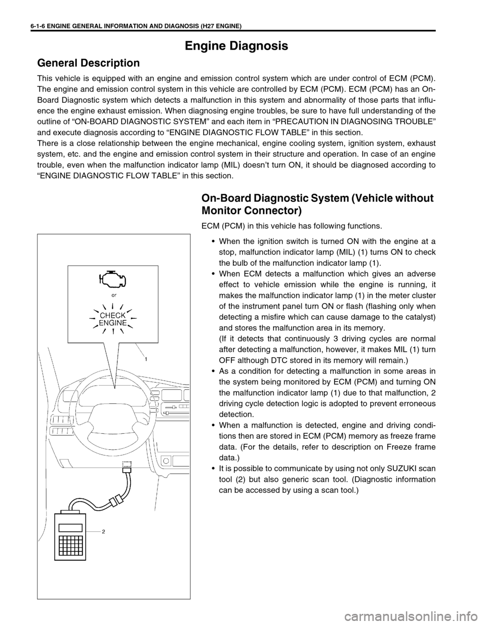
ECM (PCM) in this vehicle has following functions.
When the ignition switch is turned ON with the engine at a
stop, malfunction indicator lamp (MIL) (1) turns ON to check
the bulb of the malfunction indicator lamp (1).
When ECM detects a malfunction which gives an adverse
effect to vehicle emission while the engine is running, it
makes the malfunction indicator lamp (1) in the meter cluster
of the instrument panel turn ON or flash (flashing only when
detecting a misfire which can cause damage to the catalyst)
and stores the malfunction area in its memory.
(If it detects that continuously 3 driving cycles are normal
after detecting a malfunction, however, it makes MIL (1) turn
OFF although DTC stored in its memory will remain.)
As a condition for detecting a malfunction in some areas in
the system being monitored by ECM (PCM) and turning ON
the malfunction indicator lamp (1) due to that malfunction, 2
driving cycle detection logic is adopted to prevent erroneous
detection.
When a malfunction is detected, engine and driving condi-
tions then are stored in ECM (PCM) memory as freeze frame
data. (For the details, refer to description on Freeze frame
data.)
It is possible to communicate by using not only SUZUKI scan
tool (2) but also generic scan tool. (Diagnostic information
can be accessed by using a scan tool.)
Page 168 of 656
ENGINE GENERAL INFORMATION AND DIAGNOSIS (H27 ENGINE) 6-1-7
WARM-UP CYCLE
A warm-up cycle means sufficient vehicle operation such that the
coolant temperature has risen by at least 22°C (40°F) from
engine starting and reaches a minimum temperature of 70 °C
(160 °F).
DRIVING CYCLE
A “Driving Cycle” consists of engine startup, driving mode where
a malfunction would be detected if present and engine shutoff.
2 DRIVING CYCLE DETECTION LOGIC
The malfunction detected in the first driving cycle is stored in
ECM (PCM) memory (in the form of pending DTC) but the mal-
function indicator lamp does not light at this time. It lights up at the
second detection of same malfunction also in the next driving
cycle.
PENDING DTC
Pending DTC means a DTC detected and stored temporarily at 1
driving cycle of the DTC which is detected in the 2 driving cycle
detection logic.
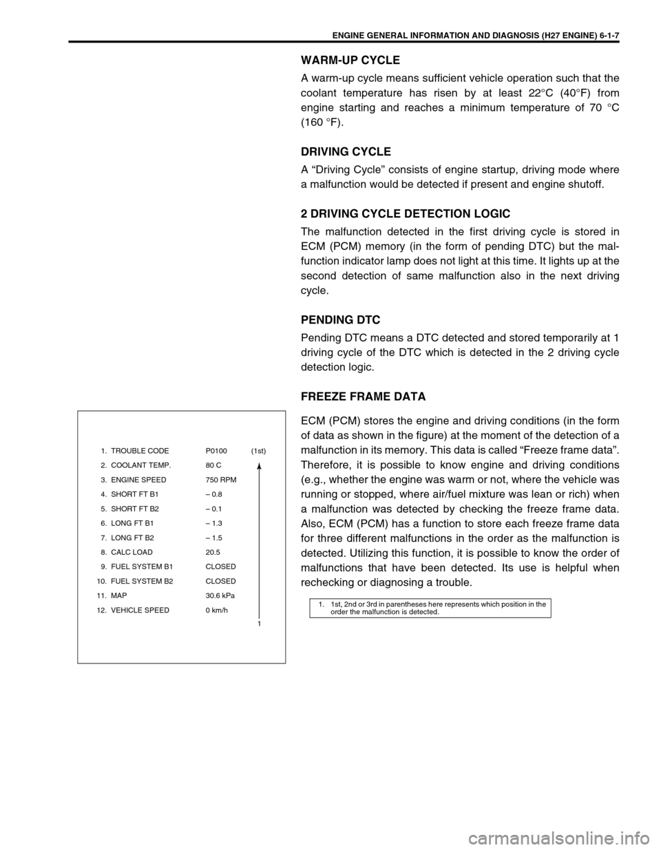
FREEZE FRAME DATA
ECM (PCM) stores the engine and driving conditions (in the form
of data as shown in the figure) at the moment of the detection of a
malfunction in its memory. This data is called “Freeze frame data”.
Therefore, it is possible to know engine and driving conditions
(e.g., whether the engine was warm or not, where the vehicle was
running or stopped, where air/fuel mixture was lean or rich) when
a malfunction was detected by checking the freeze frame data.
Also, ECM (PCM) has a function to store each freeze frame data
for three different malfunctions in the order as the malfunction is
detected. Utilizing this function, it is possible to know the order of
malfunctions that have been detected. Its use is helpful when
rechecking or diagnosing a trouble.
1. 1st, 2nd or 3rd in parentheses here represents which position in the
order the malfunction is detected.
1. TROUBLE CODE
2. COOLANT TEMP.
3. ENGINE SPEED
4. SHORT FT B1
5. SHORT FT B2
6. LONG FT B1
7. LONG FT B2
8. CALC LOAD
9. FUEL SYSTEM B1
10. FUEL SYSTEM B2
11. MAP
12. VEHICLE SPEEDP0100
80 C
750 RPM
– 0.8
– 0.1
– 1.3
– 1.5
20.5
CLOSED
CLOSED
30.6 kPa
0 km/h(1st)
1
Page 169 of 656
6-1-8 ENGINE GENERAL INFORMATION AND DIAGNOSIS (H27 ENGINE)
Priority of Freeze Frame Data
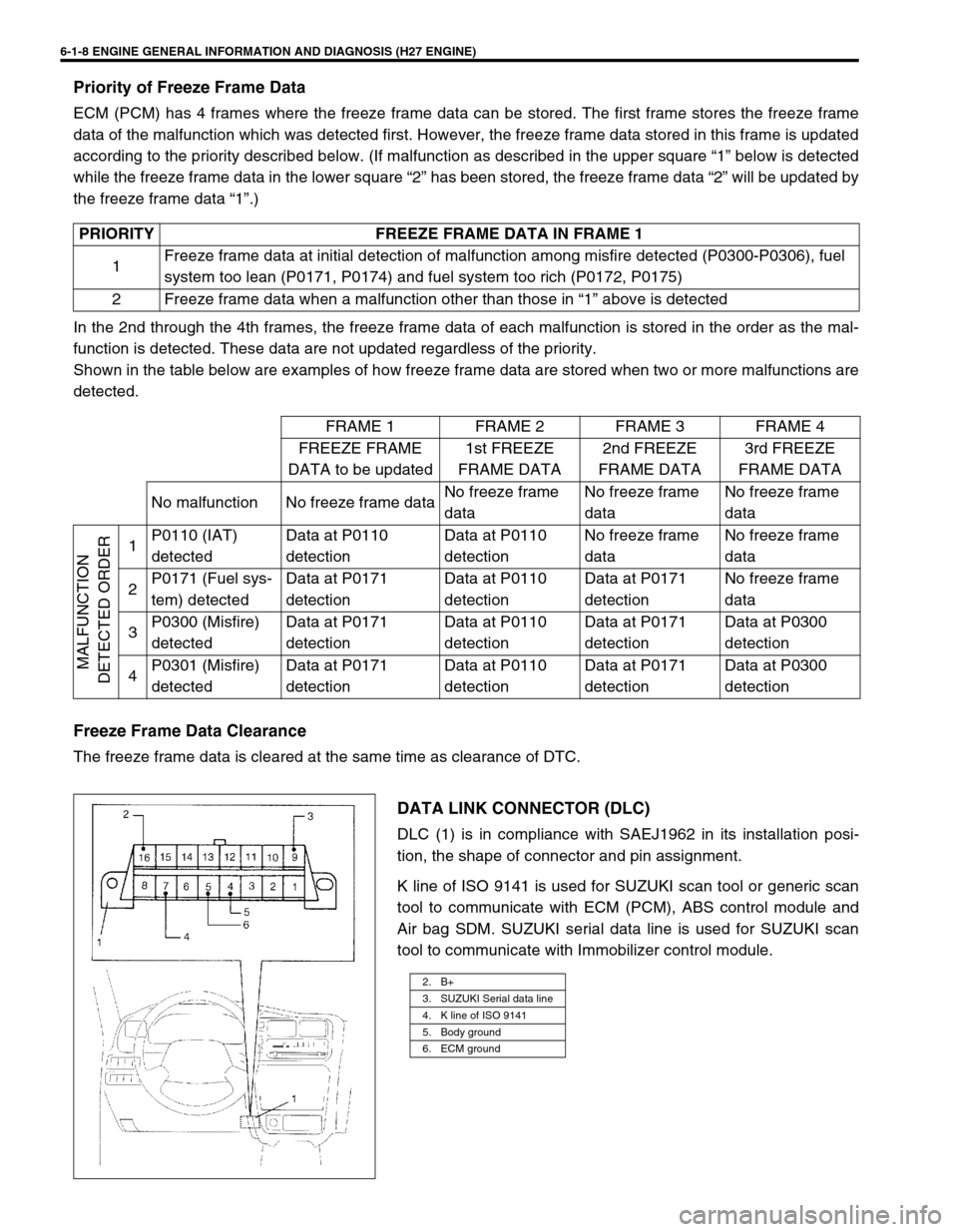
ECM (PCM) has 4 frames where the freeze frame data can be stored. The first frame stores the freeze frame
data of the malfunction which was detected first. However, the freeze frame data stored in this frame is updated
according to the priority described below. (If malfunction as described in the upper square “1” below is detected
while the freeze frame data in the lower square “2” has been stored, the freeze frame data “2” will be updated by
the freeze frame data “1”.)
In the 2nd through the 4th frames, the freeze frame data of each malfunction is stored in the order as the mal-
function is detected. These data are not updated regardless of the priority.
Shown in the table below are examples of how freeze frame data are stored when two or more malfunctions are
detected.
Freeze Frame Data Clearance
The freeze frame data is cleared at the same time as clearance of DTC.
DATA LINK CONNECTOR (DLC)
DLC (1) is in compliance with SAEJ1962 in its installation posi-
tion, the shape of connector and pin assignment.
K line of ISO 9141 is used for SUZUKI scan tool or generic scan
tool to communicate with ECM (PCM), ABS control module and
Air bag SDM. SUZUKI serial data line is used for SUZUKI scan
tool to communicate with Immobilizer control module. PRIORITY FREEZE FRAME DATA IN FRAME 1
1Freeze frame data at initial detection of malfunction among misfire detected (P0300-P0306), fuel
system too lean (P0171, P0174) and fuel system too rich (P0172, P0175)
2 Freeze frame data when a malfunction other than those in “1” above is detected
FRAME 1 FRAME 2 FRAME 3 FRAME 4
FREEZE FRAME
DATA to be updated1st FREEZE
FRAME DATA2nd FREEZE
FRAME DATA3rd FREEZE
FRAME DATA
No malfunction No freeze frame dataNo freeze frame
dataNo freeze frame
dataNo freeze frame
data
MALFUNCTION
DETECTED ORDER
1P0110 (IAT)
detectedData at P0110
detectionData at P0110
detectionNo freeze frame
dataNo freeze frame
data
2P0171 (Fuel sys-
tem) detectedData at P0171
detectionData at P0110
detectionData at P0171
detectionNo freeze frame
data
3P0300 (Misfire)
detectedData at P0171
detectionData at P0110
detectionData at P0171
detectionData at P0300
detection
4P0301 (Misfire)
detectedData at P0171
detectionData at P0110
detectionData at P0171
detectionData at P0300
detection
2. B+
3. SUZUKI Serial data line
4. K line of ISO 9141
5. Body ground
6. ECM ground