rail SUZUKI GRAND VITARA 1999 2.G Owners Manual
[x] Cancel search | Manufacturer: SUZUKI, Model Year: 1999, Model line: GRAND VITARA, Model: SUZUKI GRAND VITARA 1999 2.GPages: 656, PDF Size: 14.31 MB
Page 17 of 656

0B-4 MAINTENANCE AND LUBRICATION
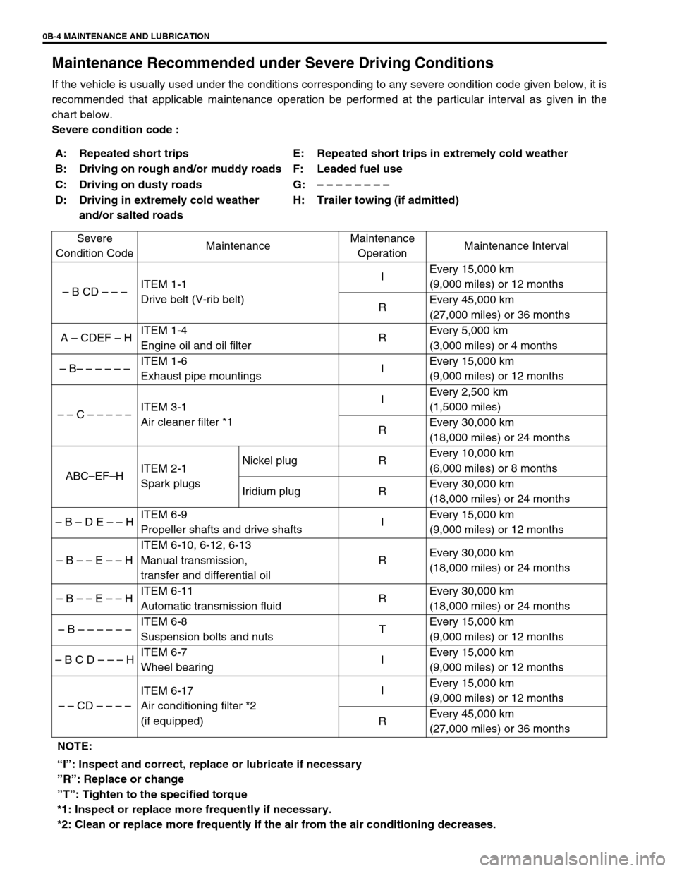
Maintenance Recommended under Severe Driving Conditions
If the vehicle is usually used under the conditions corresponding to any severe condition code given below, it is
recommended that applicable maintenance operation be performed at the particular interval as given in the
chart below.
Severe condition code :
A: Repeated short trips E: Repeated short trips in extremely cold weather
B: Driving on rough and/or muddy roads F: Leaded fuel use
C: Driving on dusty roads G: – – – – – –
– –
D: Driving in extremely cold weather
and/or salted roadsH: Trailer towing (if admitted)
Severe
Condition CodeMaintenanceMaintenance
OperationMaintenance Interval
– B CD – – –ITEM 1-1
Drive belt (V-rib belt)IEvery 15,000 km
(9,000 miles) or 12 months
REvery 45,000 km
(27,000 miles) or 36 months
A – CDEF – HITEM 1-4
Engine oil and oil filterREvery 5,000 km
(3,000 miles) or 4 months
– B– – – – – –ITEM 1-6
Exhaust pipe mountingsIEvery 15,000 km
(9,000 miles) or 12 months
– – C – – – – – ITEM 3-1
Air cleaner filter *1IEvery 2,500 km
(1,5000 miles)
REvery 30,000 km
(18,000 miles) or 24 months
ABC–EF–HITEM 2-1
Spark plugsNickel plug REvery 10,000 km
(6,000 miles) or 8 months
Iridium plug REvery 30,000 km
(18,000 miles) or 24 months
– B – D E – – HITEM 6-9
Propeller shafts and drive shafts IEvery 15,000 km
(9,000 miles) or 12 months
– B – – E – – HITEM 6-10, 6-12, 6-13
Manual transmission,
transfer and differential oilREvery 30,000 km
(18,000 miles) or 24 months
– B – – E – – HITEM 6-11
Automatic transmission fluid REvery 30,000 km
(18,000 miles) or 24 months
– B – – – – – – ITEM 6-8
Suspension bolts and nutsTEvery 15,000 km
(9,000 miles) or 12 months
– B C D – – – HITEM 6-7
Wheel bearingIEvery 15,000 km
(9,000 miles) or 12 months
– – CD – – – –ITEM 6-17
Air conditioning filter *2
(if equipped)IEvery 15,000 km
(9,000 miles) or 12 months
REvery 45,000 km
(27,000 miles) or 36 months
NOTE:
“I”: Inspect and correct, replace or lubricate if necessary
”R”: Replace or change
”T”: Tighten to the specified torque
*1: Inspect or replace more frequently if necessary.
*2: Clean or replace more frequently if the air from the air conditioning decreases.
Page 119 of 656

5C-2 PARKING AND REAR BRAKE
General Description
Drum Brake Assembly
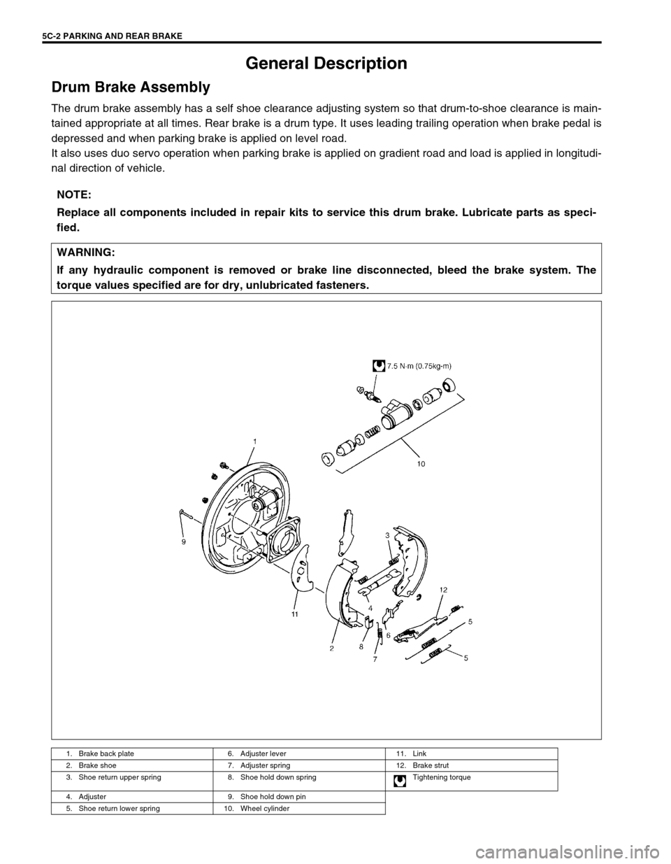
The drum brake assembly has a self shoe clearance adjusting system so that drum-to-shoe clearance is main-
tained appropriate at all times. Rear brake is a drum type. It uses leading trailing operation when brake pedal is
depressed and when parking brake is applied on level road.
It also uses duo servo operation when parking brake is applied on gradient road and load is applied in longitudi-
nal direction of vehicle.
NOTE:
Replace all components included in repair kits to service this drum brake. Lubricate parts as speci-
fied.
WARNING:
If any hydraulic component is removed or brake line disconnected, bleed the brake system. The
torque values specified are for dry, unlubricated fasteners.
1. Brake back plate 6. Adjuster lever 11. Link
2. Brake shoe 7. Adjuster spring 12. Brake strut
3. Shoe return upper spring 8. Shoe hold down spring Tightening torque
4. Adjuster 9. Shoe hold down pin
5. Shoe return lower spring 10. Wheel cylinder
Page 312 of 656

ENGINE MECHANICAL (H27 ENGINE) 6A2-25
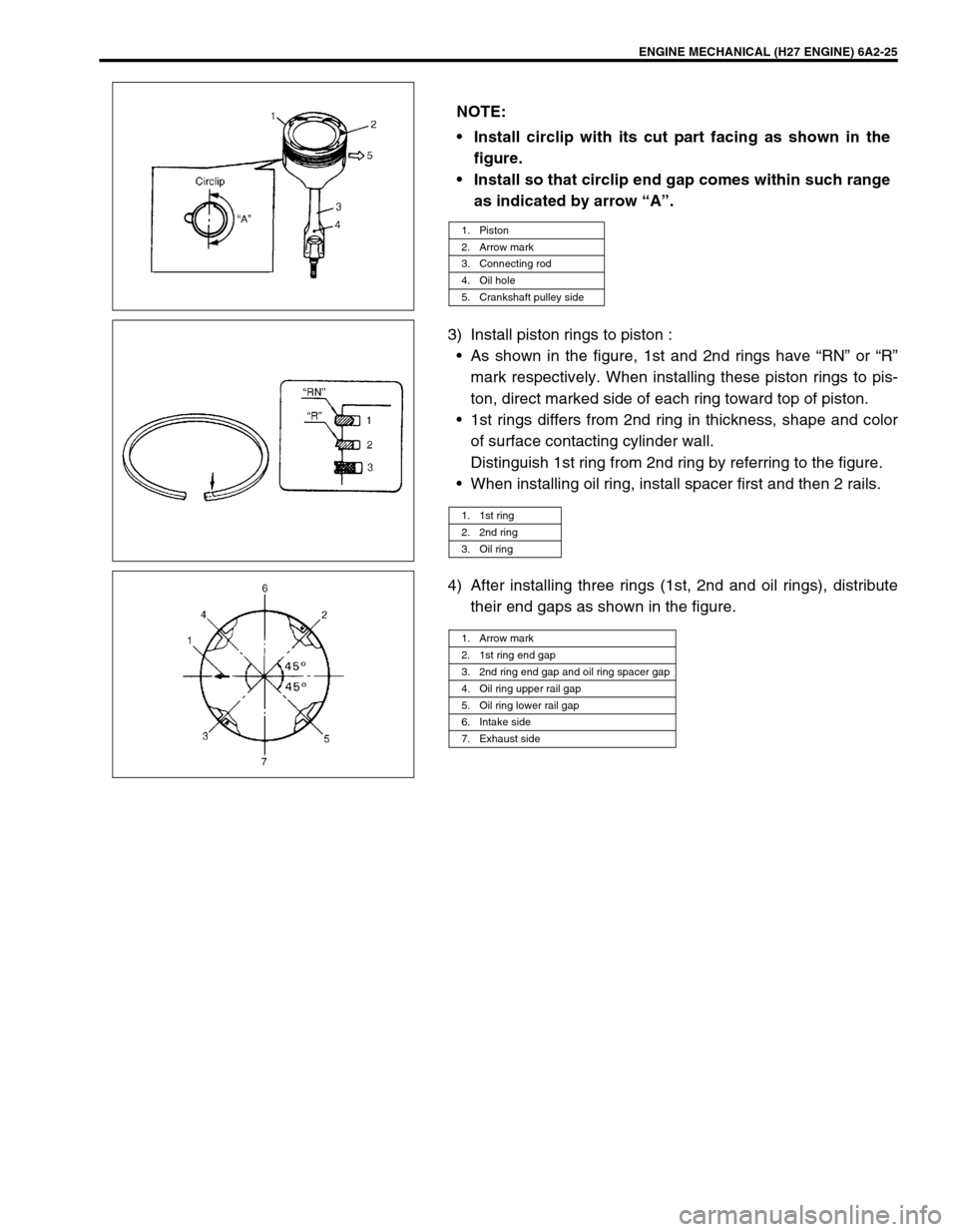
3) Install piston rings to piston :
•As shown in the figure, 1st and 2nd rings have “RN” or “R”
mark respectively. When installing these piston rings to pis-
ton, direct marked side of each ring toward top of piston.
•1st rings differs from 2nd ring in thickness, shape and color
of surface contacting cylinder wall.
Distinguish 1st ring from 2nd ring by referring to the figure.
•When installing oil ring, install spacer first and then 2 rails.
4) After installing three rings (1st, 2nd and oil rings), distribute
their end gaps as shown in the figure. NOTE:
Install circlip with its cut part facing as shown in the
figure.
Install so that circlip end gap comes within such range
as indicated by arrow “A”.
1. Piston
2. Arrow mark
3. Connecting rod
4. Oil hole
5. Crankshaft pulley side
1. 1st ring
2. 2nd ring
3. Oil ring
1. Arrow mark
2. 1st ring end gap
3. 2nd ring end gap and oil ring spacer gap
4. Oil ring upper rail gap
5. Oil ring lower rail gap
6. Intake side
7. Exhaust side
Page 452 of 656

AUTOMATIC TRANSMISSION (4 A/T) 7B1-43
On-Vehicle Service
Maintenance Service
Fluid level
LEVEL CHECK AT NORMAL OPERATING TEMPERATURE
1) Stop vehicle and place it level.
2) Apply parking brake and place chocks against wheels.
3) With selector at P position, start engine.
4) Warm up engine till fluid temperature reaches normal oper-
ating temperature (70 – 80 °C (158 – 176 °F)). As a guide to
check fluid temperature, warm up engine till engine coolant
temperature meter indicated around 1 unit above “C” point.
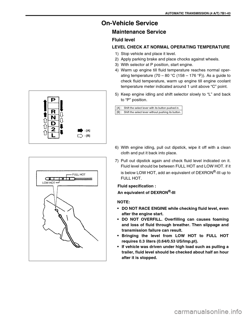
5) Keep engine idling and shift selector slowly to “L” and back
to “P” position.
6) With engine idling, pull out dipstick, wipe it off with a clean
cloth and put it back into place.
7) Pull out dipstick again and check fluid level indicated on it.
Fluid level should be between FULL HOT and LOW HOT. if it
is below LOW HOT, add an equivalent of DEXRON
®-III up to
FULL HOT.
Fluid specification :
An equivalent of DEXRON
®-III
[A] : Shift the select lever with its button pushed in.
[B] : Shift the select lever without pushing its button.
NOTE:
DO NOT RACE ENGINE while checking fluid level, even
after the engine start.
DO NOT OVERFILL. Overfilling can causes foaming
and loss of fluid through breather. Then slippage and
transmission failure can result.
Bringing the level from LOW HOT to FULL HOT
requires 0.3 liters (0.64/0.53 US/lmp.pt).
If vehicle was driven under high load such as pulling a
trailer, fluid level should be checked about half an hour
after it is stopped.