water pump SUZUKI GRAND VITARA 1999 2.G Owners Manual
[x] Cancel search | Manufacturer: SUZUKI, Model Year: 1999, Model line: GRAND VITARA, Model: SUZUKI GRAND VITARA 1999 2.GPages: 656, PDF Size: 14.31 MB
Page 18 of 656
MAINTENANCE AND LUBRICATION 0B-5
Maintenance Service
Engine and Emission Control
ITEM 1-1
Drive belt inspection and replacement
WATER PUMP AND GENERATOR DRIVE BELT INSPEC-
TION
1) Disconnect negative (–) cable at battery.
2) Inspect belt for cracks, cuts, deformation, wear and cleanli-
ness. If any defect exists, replace.
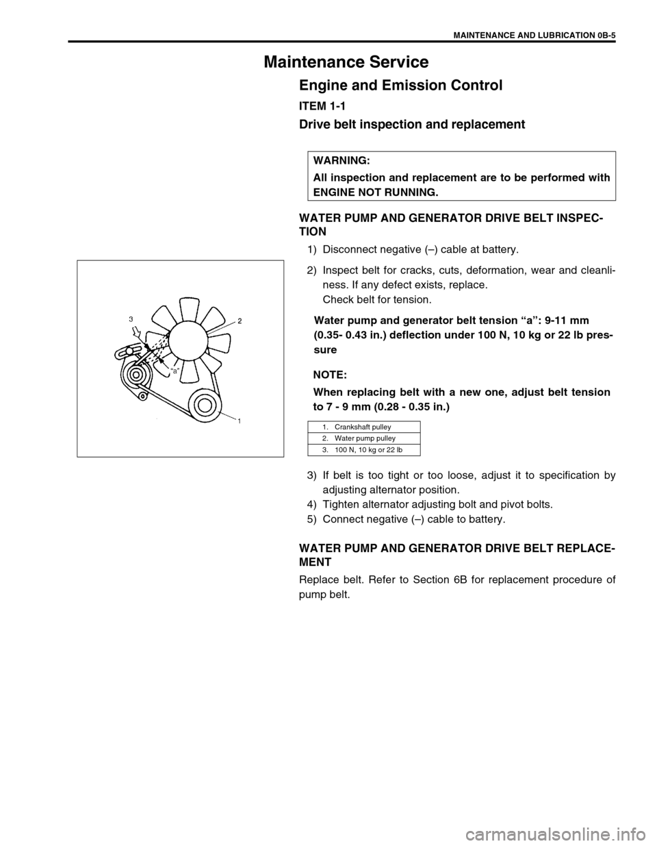
Check belt for tension.
Water pump and generator belt tension “a”: 9-11 mm
(0.35- 0.43 in.) deflection under 100 N, 10 kg or 22 lb pres-
sure
3) If belt is too tight or too loose, adjust it to specification by
adjusting alternator position.
4) Tighten alternator adjusting bolt and pivot bolts.
5) Connect negative (–) cable to battery.
WATER PUMP AND GENERATOR DRIVE BELT REPLACE-
MENT
Replace belt. Refer to Section 6B for replacement procedure of
pump belt.WARNING:
All inspection and replacement are to be performed with
ENGINE NOT RUNNING.
NOTE:
When replacing belt with a new one, adjust belt tension
to 7 - 9 mm (0.28 - 0.35 in.)
1. Crankshaft pulley
2. Water pump pulley
3. 100 N, 10 kg or 22 lb
Page 174 of 656
ENGINE GENERAL INFORMATION AND DIAGNOSIS (H27 ENGINE) 6-1-13
STEP 2. DIAGNOSTIC TROUBLE CODE (DTC)/FREEZE FRAME DATA CHECK
First, check DTC, referring to “DIAGNOSTIC TROUBLE CODE CHECK” in this section. If DTC is indicated,
record DTC and freeze frame data.
After that clear DTC referring to “DIAGNOSTIC TROUBLE CODE CLEARANCE” in this section. DTC indicates
malfunction that occurred in the system but does not indicate whether it exists now or it occurred in the past and
the normal condition has been restored now. To check which case applies, check the symptom in question
according to Step 5 and recheck DTC according to Step 6, 7.
Attempt to diagnose a trouble based on DTC in this step only or failure to clear the DTC (including pending DTC)
in this step will lead to incorrect diagnosis, trouble diagnosis of a normal circuit or difficulty in troubleshooting.
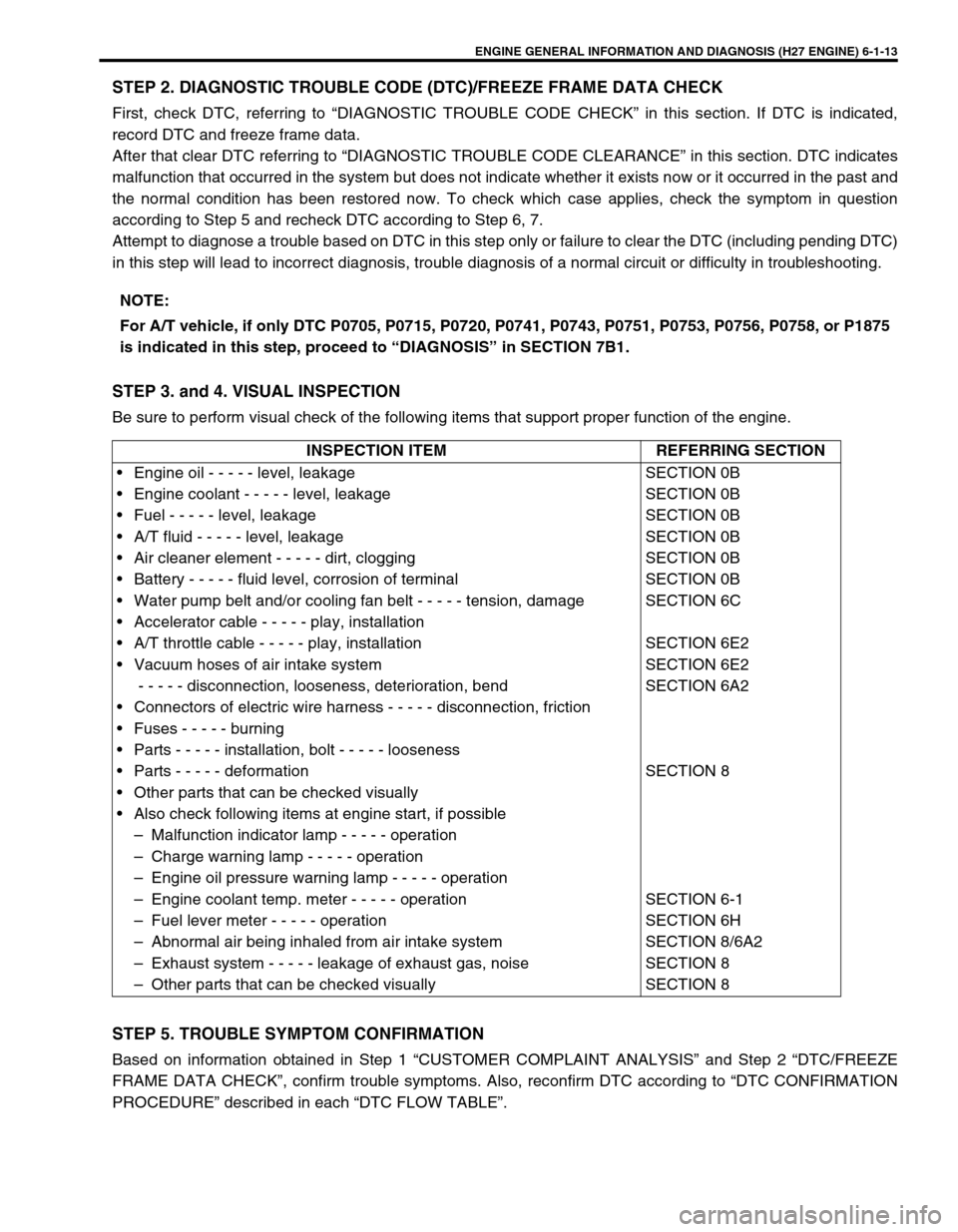
STEP 3. and 4. VISUAL INSPECTION
Be sure to perform visual check of the following items that support proper function of the engine.
STEP 5. TROUBLE SYMPTOM CONFIRMATION
Based on information obtained in Step 1 “CUSTOMER COMPLAINT ANALYSIS” and Step 2 “DTC/FREEZE
FRAME DATA CHECK”, confirm trouble symptoms. Also, reconfirm DTC according to “DTC CONFIRMATION
PROCEDURE” described in each “DTC FLOW TABLE”.NOTE:
For A/T vehicle, if only DTC P0705, P0715, P0720, P0741, P0743, P0751, P0753, P0756, P0758, or P1875
is indicated in this step, proceed to “DIAGNOSIS” in SECTION 7B1.
INSPECTION ITEM REFERRING SECTION
• Engine oil - - - - - level, leakage
• Engine coolant - - - - - level, leakage
• Fuel - - - - - level, leakage
• A/T fluid - - - - - level, leakage
• Air cleaner element - - - - - dirt, clogging
• Battery - - - - - fluid level, corrosion of terminal
• Water pump belt and/or cooling fan belt - - - - - tension, damage
• Accelerator cable - - - - - play, installation
• A/T throttle cable - - - - - play, installation
• Vacuum hoses of air intake system
- - - - - disconnection, looseness, deterioration, bend
• Connectors of electric wire harness - - - - - disconnection, friction
• Fuses - - - - - burning
• Parts - - - - - installation, bolt - - - - - looseness
• Parts - - - - - deformation
• Other parts that can be checked visually
• Also check following items at engine start, if possible
– Malfunction indicator lamp - - - - - operation
– Charge warning lamp - - - - - operation
– Engine oil pressure warning lamp - - - - - operation
– Engine coolant temp. meter - - - - - operation
– Fuel lever meter - - - - - operation
– Abnormal air being inhaled from air intake system
– Exhaust system - - - - - leakage of exhaust gas, noise
– Other parts that can be checked visuallySECTION 0B
SECTION 0B
SECTION 0B
SECTION 0B
SECTION 0B
SECTION 0B
SECTION 6C
SECTION 6E2
SECTION 6E2
SECTION 6A2
SECTION 8
SECTION 6-1
SECTION 6H
SECTION 8/6A2
SECTION 8
SECTION 8
Page 194 of 656
ENGINE GENERAL INFORMATION AND DIAGNOSIS (H27 ENGINE) 6-1-33
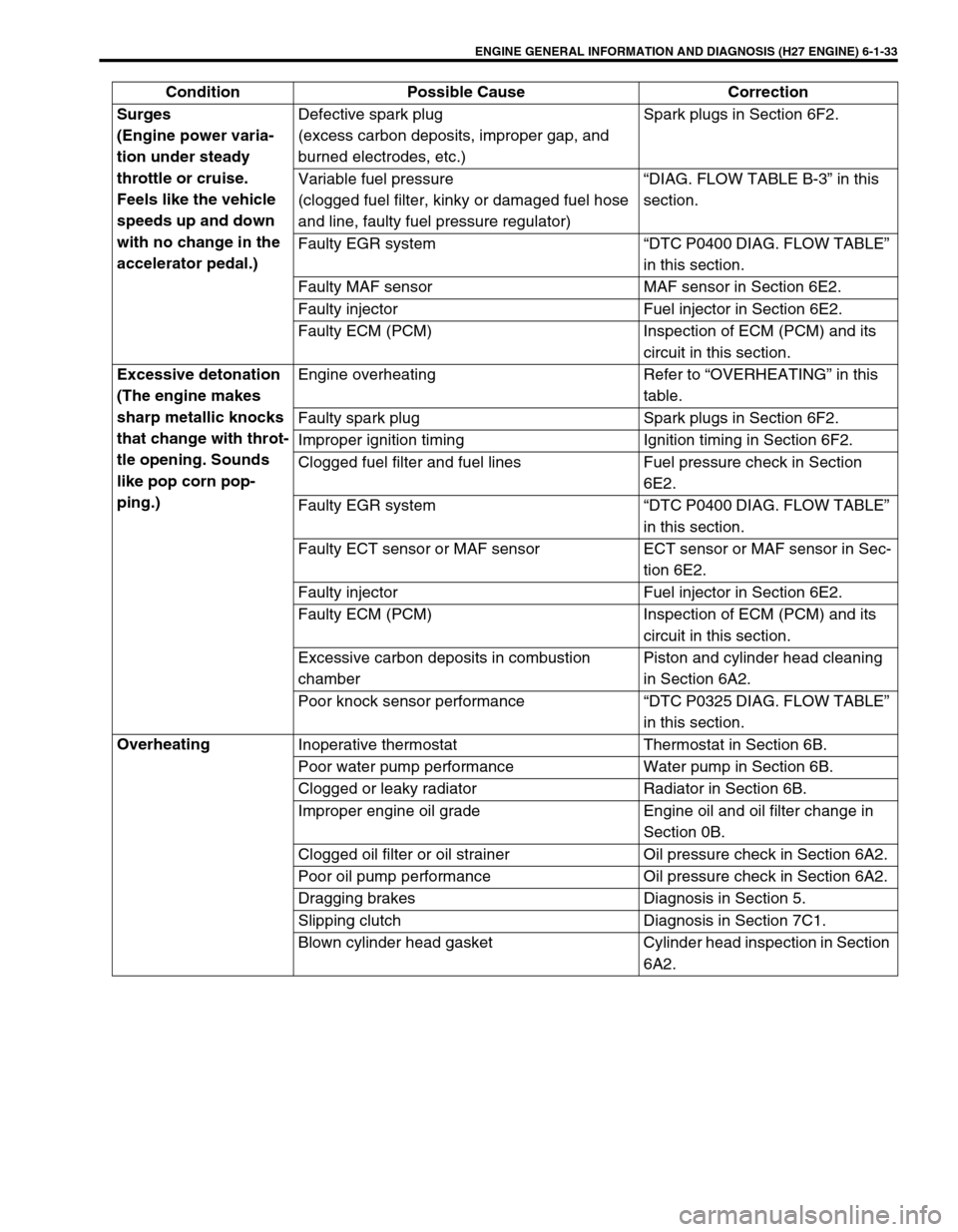
Surges
(Engine power varia-
tion under steady
throttle or cruise.
Feels like the vehicle
speeds up and down
with no change in the
accelerator pedal.)Defective spark plug
(excess carbon deposits, improper gap, and
burned electrodes, etc.)Spark plugs in Section 6F2.
Variable fuel pressure
(clogged fuel filter, kinky or damaged fuel hose
and line, faulty fuel pressure regulator)“DIAG. FLOW TABLE B-3” in this
section.
Faulty EGR system “DTC P0400 DIAG. FLOW TABLE”
in this section.
Faulty MAF sensor MAF sensor in Section 6E2.
Faulty injector Fuel injector in Section 6E2.
Faulty ECM (PCM) Inspection of ECM (PCM) and its
circuit in this section.
Excessive detonation
(The engine makes
sharp metallic knocks
that change with throt-
tle opening. Sounds
like pop corn pop-
ping.)Engine overheating Refer to “OVERHEATING” in this
table.
Faulty spark plug Spark plugs in Section 6F2.
Improper ignition timing Ignition timing in Section 6F2.
Clogged fuel filter and fuel lines Fuel pressure check in Section
6E2.
Faulty EGR system “DTC P0400 DIAG. FLOW TABLE”
in this section.
Faulty ECT sensor or MAF sensor ECT sensor or MAF sensor in Sec-
tion 6E2.
Faulty injector Fuel injector in Section 6E2.
Faulty ECM (PCM) Inspection of ECM (PCM) and its
circuit in this section.
Excessive carbon deposits in combustion
chamberPiston and cylinder head cleaning
in Section 6A2.
Poor knock sensor performance “DTC P0325 DIAG. FLOW TABLE”
in this section.
Overheating
Inoperative thermostat Thermostat in Section 6B.
Poor water pump performance Water pump in Section 6B.
Clogged or leaky radiator Radiator in Section 6B.
Improper engine oil grade Engine oil and oil filter change in
Section 0B.
Clogged oil filter or oil strainer Oil pressure check in Section 6A2.
Poor oil pump performance Oil pressure check in Section 6A2.
Dragging brakes Diagnosis in Section 5.
Slipping clutch Diagnosis in Section 7C1.
Blown cylinder head gasket Cylinder head inspection in Section
6A2. Condition Possible Cause Correction
Page 307 of 656
6A2-20 ENGINE MECHANICAL (H27 ENGINE)
12) Install oil pan and oil pump strainer.
Refer to “OIL PAN AND OIL PUMP STRAINER” in this sec-
tion.
13) Install cylinder head cover.
Refer to “CYLINDER HEAD COVER” in this section.
14) Install exhaust manifold.
Refer to “EXHAUST MANIFOLD” in this section.
15) Install radiator outlet pipe, radiator, cooling fan and water
hose.
Refer to “COOLING WATER PIPES OR HOSES”, “RADIA-
TOR” and “COOLING FAN AND FAN CLUTCH” in Section
6B.
16) Install throttle body and intake manifold.
Refer to “THROTTLE BODY AND INTAKE MANIFOLD” in
this section.
17) Adjust water pump drive belt tension.
Refer to “COOLING FAN BELT TENSION CHECK AND
ADJUSTMENT” in Section 6B.
18) Adjust power steering pump drive belt tension.
Refer to “POWER STEERING PUMP DRIVE BELT” in Sec-
tion 3B1.
19) Adjust accelerator cable play and A/T throttle cable play.
Refer to “ACCELERATOR CABLE ADJUSTMENT” and “A/T
THROTTLE CABLE ADJUSTMENT (A/T VEHICLE)” in Sec-
tion 6E2.
20) Check to ensure that all removed parts are back in place.
Reinstall any necessary parts which have not been rein-
stalled.
21) Refill engine with engine oil, referring to “ENGINE OIL
CHANGE” in Section 0B.
22) Refill cooling system referring to “COOLING SYSTEM
FLUSH AND REFILL” in Section 6B.
23) Refill front differential housing with gear oil if drained, refer-
ring to “MAINTENANCE SERVICE” in Section 7E.
24) Connect negative cable at battery.
25) Check ignition timing and adjust as necessary, referring to
“IGNITION TIMING CHECK AND ADJUSTMENT” in Section
6F2.
26) Verify that there is no fuel leakage, water leakage, oil leak-
age and exhaust gas leakage at each connection.
27) Check wheel alignment, referring to “STEERING ANGLE” in
Section 3A.
Page 314 of 656
ENGINE MECHANICAL (H27 ENGINE) 6A2-27
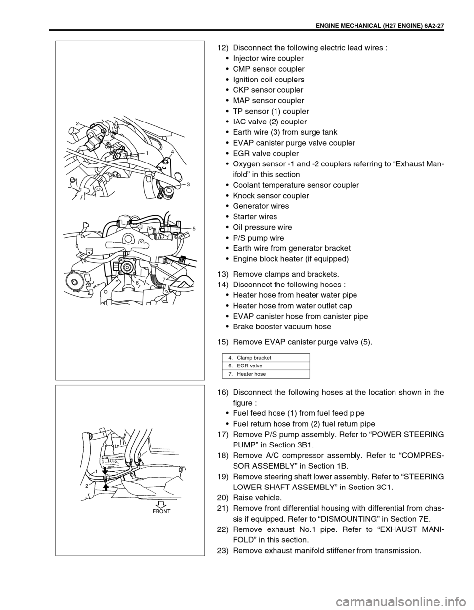
12) Disconnect the following electric lead wires :
•Injector wire coupler
•CMP sensor coupler
•Ignition coil couplers
•CKP sensor coupler
•MAP sensor coupler
•TP sensor (1) coupler
•IAC valve (2) coupler
•Earth wire (3) from surge tank
•EVAP canister purge valve coupler
•EGR valve coupler
•Oxygen sensor -1 and -2 couplers referring to “Exhaust Man-
ifold” in this section
•Coolant temperature sensor coupler
•Knock sensor coupler
•Generator wires
•Starter wires
•Oil pressure wire
•P/S pump wire
•Earth wire from generator bracket
•Engine block heater (if equipped)
13) Remove clamps and brackets.
14) Disconnect the following hoses :
•Heater hose from heater water pipe
•Heater hose from water outlet cap
•EVAP canister hose from canister pipe
•Brake booster vacuum hose
15) Remove EVAP canister purge valve (5).
16) Disconnect the following hoses at the location shown in the
figure :
•Fuel feed hose (1) from fuel feed pipe
•Fuel return hose from (2) fuel return pipe
17) Remove P/S pump assembly. Refer to “POWER STEERING
PUMP” in Section 3B1.
18) Remove A/C compressor assembly. Refer to “COMPRES-
SOR ASSEMBLY” in Section 1B.
19) Remove steering shaft lower assembly. Refer to “STEERING
LOWER SHAFT ASSEMBLY” in Section 3C1.
20) Raise vehicle.
21) Remove front differential housing with differential from chas-
sis if equipped. Refer to “DISMOUNTING” in Section 7E.
22) Remove exhaust No.1 pipe. Refer to “EXHAUST MANI-
FOLD” in this section.
23) Remove exhaust manifold stiffener from transmission.
4. Clamp bracket
6. EGR valve
7. Heater hose
2
14
3
75
6
Page 317 of 656
![SUZUKI GRAND VITARA 1999 2.G Owners Manual 6A2-30 ENGINE MECHANICAL (H27 ENGINE)
Main Bearings, Crankshaft and Cylinder Block
1. Cylinder block 6. Rear oil seal 11. O-ring [A]: Sealant application amount
2. Lower crankcase :
Apply sealant 9900 SUZUKI GRAND VITARA 1999 2.G Owners Manual 6A2-30 ENGINE MECHANICAL (H27 ENGINE)
Main Bearings, Crankshaft and Cylinder Block
1. Cylinder block 6. Rear oil seal 11. O-ring [A]: Sealant application amount
2. Lower crankcase :
Apply sealant 9900](/img/20/7583/w960_7583-316.png)
6A2-30 ENGINE MECHANICAL (H27 ENGINE)
Main Bearings, Crankshaft and Cylinder Block
1. Cylinder block 6. Rear oil seal 11. O-ring [A]: Sealant application amount
2. Lower crankcase :
Apply sealant 99000-31150 to lower
crankcase mating surface.7. Flywheel (M/T) Drive plate
(A/T)12. Clutch housing plate Tightening Torque
3. Crankshaft 8. Water pump 13. Cap bolt Do not reuse
4. Main bearing 9. O-ring 14. Lower crankcase bolt Apply engine oil to sliding
surface of each parts.
5. Thrust bearing :
Set bearing facing grooved side to
crank weds.10. Timing chain oil jet 15. Knock sensor“a”: Width 3 mm (0.12 in.)
“b”: Height 2 mm (0.08 in.)
Page 412 of 656
AUTOMATIC TRANSMISSION (4 A/T) 7B1-3
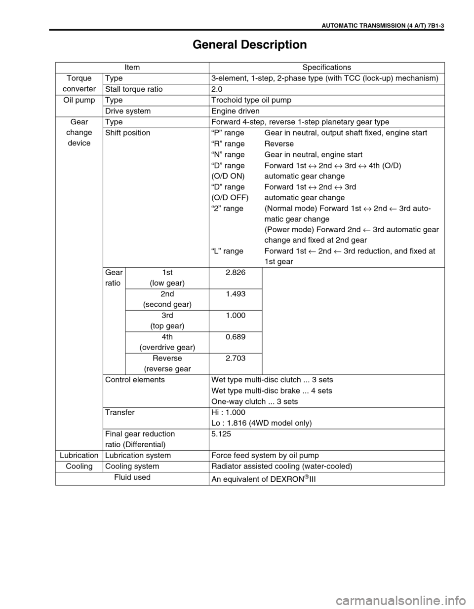
General Description
Item Specifications
Torque
converterType 3-element, 1-step, 2-phase type (with TCC (lock-up) mechanism)
Stall torque ratio 2.0
Oil pump Type Trochoid type oil pump
Drive system Engine driven
Gear
change
deviceType Forward 4-step, reverse 1-step planetary gear type
Shift position“P” range Gear in neutral, output shaft fixed, engine start
“R” range Reverse
“N” range Gear in neutral, engine start
“D” range
(O/D ON)Forward 1st ↔ 2nd ↔ 3rd ↔ 4th (O/D)
automatic gear change
“D” range
(O/D OFF)Forward 1st ↔ 2nd ↔ 3rd
automatic gear change
“2” range (Normal mode) Forward 1st ↔ 2nd ← 3rd auto-
matic gear change
(Power mode) Forward 2nd ← 3rd automatic gear
change and fixed at 2nd gear
“L” range Forward 1st ← 2nd ← 3rd reduction, and fixed at
1st gear
Gear
ratio1st
(low gear)2.826
2nd
(second gear)1.493
3rd
(top gear)1.000
4th
(overdrive gear)0.689
Reverse
(reverse gear2.703
Control elements Wet type multi-disc clutch ... 3 sets
Wet type multi-disc brake ... 4 sets
One-way clutch ... 3 sets
Transfer Hi : 1.000
Lo : 1.816 (4WD model only)
Final gear reduction
ratio (Differential)5.125
Lubrication Lubrication system Force feed system by oil pump
Cooling Cooling system Radiator assisted cooling (water-cooled)
Fluid used
An equivalent of DEXRON
III