Ecm SUZUKI GRAND VITARA 2001 2.G Owners Manual
[x] Cancel search | Manufacturer: SUZUKI, Model Year: 2001, Model line: GRAND VITARA, Model: SUZUKI GRAND VITARA 2001 2.GPages: 656, PDF Size: 14.31 MB
Page 282 of 656

ENGINE GENERAL INFORMATION AND DIAGNOSIS (H27 ENGINE) 6-1-121
Table B-4 Idle Air Control System Inspection
WIRING DIAGRAM
INSPECTION
1. Throttle body 3. ECM (PCM) 5. Main fuse
2. Idle air control valve 4. Sensed information 6. Main relay
Step Action Yes No
1 Check engine idle speed and IAC duty
referring to “IDLE SPEED/IAC DUTY
INSPECTION” in Section 6E2.
Is idle speed/IAC duty within specifica-
tion?Go to Step 2. Go to Step 3.
2 Is engine idle speed kept specified speed
even with headlights turned ON?System is in good condition. Go to Step 3.
Page 283 of 656
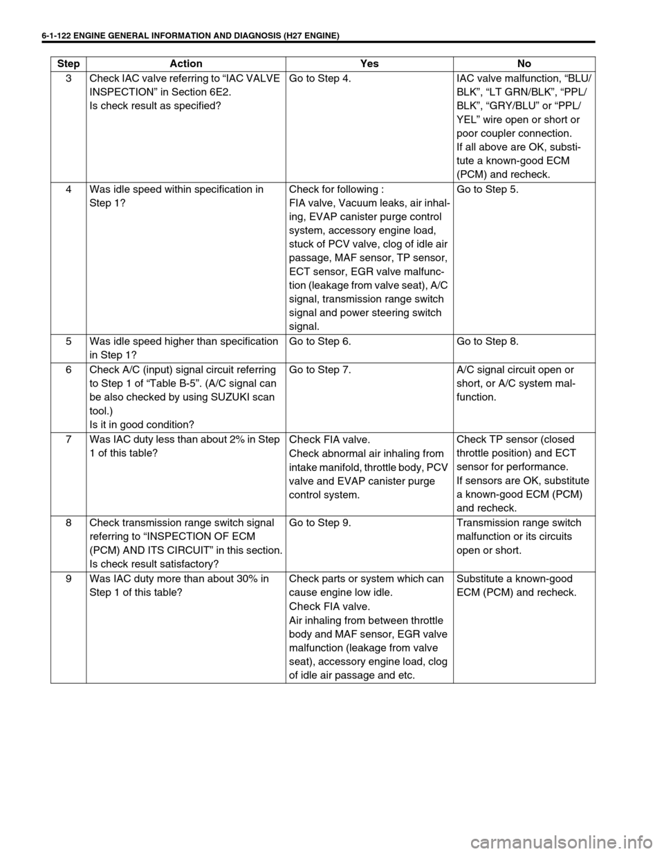
6-1-122 ENGINE GENERAL INFORMATION AND DIAGNOSIS (H27 ENGINE)
3 Check IAC valve referring to “IAC VALVE
INSPECTION” in Section 6E2.
Is check result as specified?Go to Step 4. IAC valve malfunction, “BLU/
BLK”, “LT GRN/BLK”, “PPL/
BLK”, “GRY/BLU” or “PPL/
YEL” wire open or short or
poor coupler connection.
If all above are OK, substi-
tute a known-good ECM
(PCM) and recheck.
4 Was idle speed within specification in
Step 1?Check for following :
FIA valve, Vacuum leaks, air inhal-
ing, EVAP canister purge control
system, accessory engine load,
stuck of PCV valve, clog of idle air
passage, MAF sensor, TP sensor,
ECT sensor, EGR valve malfunc-
tion (leakage from valve seat), A/C
signal, transmission range switch
signal and power steering switch
signal.Go to Step 5.
5 Was idle speed higher than specification
in Step 1?Go to Step 6. Go to Step 8.
6 Check A/C (input) signal circuit referring
to Step 1 of “Table B-5”. (A/C signal can
be also checked by using SUZUKI scan
tool.)
Is it in good condition?Go to Step 7. A/C signal circuit open or
short, or A/C system mal-
function.
7 Was IAC duty less than about 2% in Step
1 of this table?
Check FIA valve.
Check abnormal air inhaling from
intake manifold, throttle body, PCV
valve and EVAP canister purge
control system.Check TP sensor (closed
throttle position) and ECT
sensor for performance.
If sensors are OK, substitute
a known-good ECM (PCM)
and recheck.
8 Check transmission range switch signal
referring to “INSPECTION OF ECM
(PCM) AND ITS CIRCUIT” in this section.
Is check result satisfactory?Go to Step 9. Transmission range switch
malfunction or its circuits
open or short.
9 Was IAC duty more than about 30% in
Step 1 of this table?Check parts or system which can
cause engine low idle.
Check FIA valve.
Air inhaling from between throttle
body and MAF sensor, EGR valve
malfunction (leakage from valve
seat), accessory engine load, clog
of idle air passage and etc.Substitute a known-good
ECM (PCM) and recheck. Step Action Yes No
Page 284 of 656

ENGINE GENERAL INFORMATION AND DIAGNOSIS (H27 ENGINE) 6-1-123
Table B-5 A/C Signal Circuits Inspection (If Equipped)
WIRING DIAGRAM
INSPECTION
1. A/C control module (amplifier)
2. ECM (PCM)
Step Action Yes No
1 Check A/C Signal Circuit.
1) Check voltage at terminal E61-17 with ignition
switch ON.
A/C signal circuit specification :
A/C switch and/or heater blower switch OFF (A/
C is not operating) : 10 – 14 V
Both A/C switch and heater blower switch ON :
0 – 1.5 V
Are check result as specified?Go to Step 2.“YEL/BLK” circuit open or
short, Evaporative tem-
perature is below 1°C
(34°F) or faulty A/C sys-
tem.
2 Check A/C Cut Signal Circuit.
1) Check voltage at terminal E61-8.
A/C cut signal specification :
While engine running and A/C switch and/or
heater blower switch OFF
(A/C is not operating) : 0 – 1.5 V
While engine running at idle speed and both A/
C switch and heater blower switch ON
(A/C is operating) : 10 – 14 V
Are check result as specified?A/C control signal cir-
cuits are in good con-
dition.“GRY/WHT” circuit open
or short, Poor perfor-
mance of ECT sensor, TP
sensor, Engine start sig-
nal inputted or A/C ampli-
fier malfunction.
If none of the above
exists, substitute a
known-good ECM (PCM)
and recheck.
Page 285 of 656
6-1-124 ENGINE GENERAL INFORMATION AND DIAGNOSIS (H27 ENGINE)
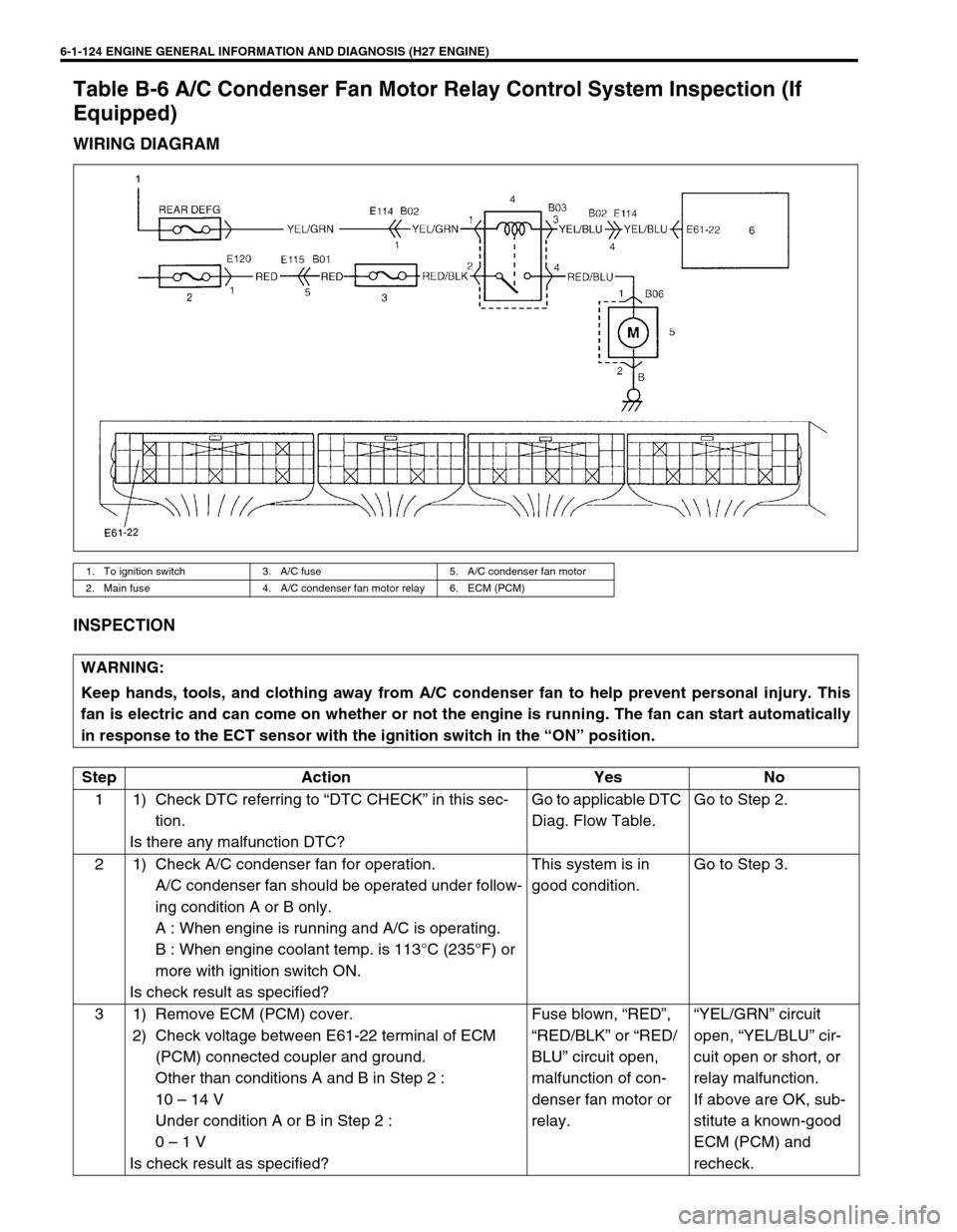
Table B-6 A/C Condenser Fan Motor Relay Control System Inspection (If
Equipped)
WIRING DIAGRAM
INSPECTION
1. To ignition switch 3. A/C fuse 5. A/C condenser fan motor
2. Main fuse 4. A/C condenser fan motor relay 6. ECM (PCM)
WARNING:
Keep hands, tools, and clothing away from A/C condenser fan to help prevent personal injury. This
fan is electric and can come on whether or not the engine is running. The fan can start automatically
in response to the ECT sensor with the ignition switch in the “ON” position.
Step Action Yes No
1 1) Check DTC referring to “DTC CHECK” in this sec-
tion.
Is there any malfunction DTC?Go to applicable DTC
Diag. Flow Table.Go to Step 2.
2 1) Check A/C condenser fan for operation.
A/C condenser fan should be operated under follow-
ing condition A or B only.
A : When engine is running and A/C is operating.
B : When engine coolant temp. is 113°C (235°F) or
more with ignition switch ON.
Is check result as specified?This system is in
good condition.Go to Step 3.
3 1) Remove ECM (PCM) cover.
2) Check voltage between E61-22 terminal of ECM
(PCM) connected coupler and ground.
Other than conditions A and B in Step 2 :
10 – 14 V
Under condition A or B in Step 2 :
0 – 1 V
Is check result as specified?Fuse blown, “RED”,
“RED/BLK” or “RED/
BLU” circuit open,
malfunction of con-
denser fan motor or
relay.“YEL/GRN” circuit
open, “YEL/BLU” cir-
cuit open or short, or
relay malfunction.
If above are OK, sub-
stitute a known-good
ECM (PCM) and
recheck.
Page 335 of 656
6E2-2 ENGINE AND EMISSION CONTROL SYSTEM (SEQUENTIAL MULTIPORT FUEL INJECTION FOR H27 ENGINE)
Fuel injector.......................................... 6E2-26
Electronic Control System........................ 6E2-31
Engine control module (ECM)/
powertrain control module (PCM) ........ 6E2-31
Mass air flow sensor (MAF sensor)...... 6E2-32
Intake air temperature (IAT) sensor ..... 6E2-34
Throttle position sensor (TP sensor) .... 6E2-35
Engine coolant temperature sensor
(ECT sensor) ........................................ 6E2-36
Heated oxygen sensor (sensor 1) ........ 6E2-37
Heated oxygen sensor (sensor 2) ........ 6E2-38
Vehicle speed sensor (VSS) ................ 6E2-39
Manifold absolute pressure sensor ...... 6E2-39
Fuel level sensor (sender gauge)......... 6E2-41
Crankshaft position sensor................... 6E2-41Main relay ............................................ 6E2-41
Fuel pump relay ................................... 6E2-42
Fuel cut operation ................................ 6E2-43
Emission Control System......................... 6E2-44
EGR system (if equipped) .................... 6E2-44
EVAP canister ...................................... 6E2-45
Vacuum passage ................................. 6E2-46
PCV System ............................................ 6E2-47
PCV hose ............................................. 6E2-47
PCV valve ............................................ 6E2-47
PCV system ......................................... 6E2-48
Tightening Torque Specification.............. 6E2-48
Special Tool ............................................... 6E2-48
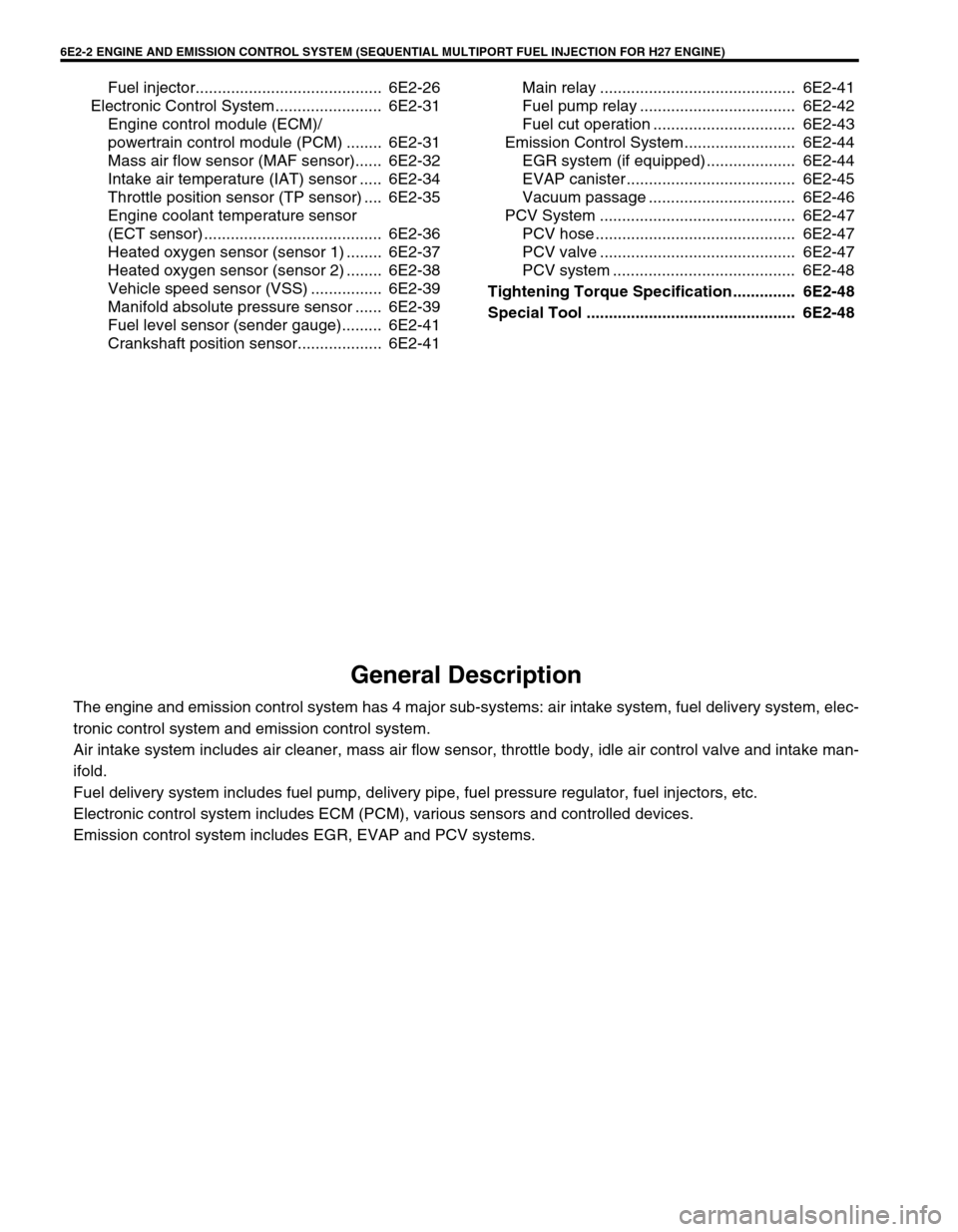
General Description
The engine and emission control system has 4 major sub-systems: air intake system, fuel delivery system, elec-
tronic control system and emission control system.
Air intake system includes air cleaner, mass air flow sensor, throttle body, idle air control valve and intake man-
ifold.
Fuel delivery system includes fuel pump, delivery pipe, fuel pressure regulator, fuel injectors, etc.
Electronic control system includes ECM (PCM), various sensors and controlled devices.
Emission control system includes EGR, EVAP and PCV systems.
Page 338 of 656
ENGINE AND EMISSION CONTROL SYSTEM (SEQUENTIAL MULTIPORT FUEL INJECTION FOR H27 ENGINE) 6E2-5
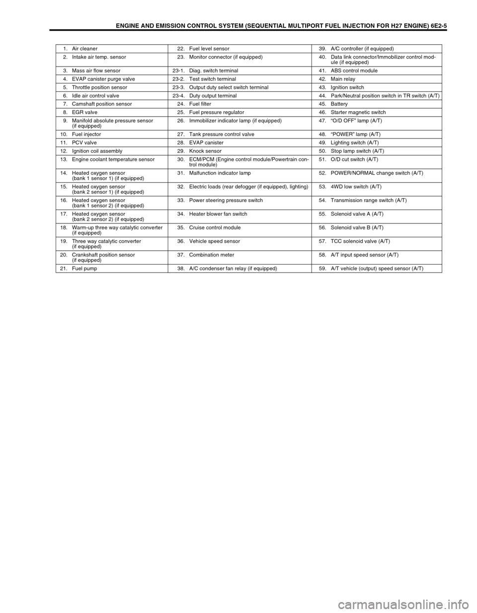
1. Air cleaner 22. Fuel level sensor 39. A/C controller (if equipped)
2. Intake air temp. sensor 23. Monitor connector (if equipped) 40. Data link connector/Immobilizer control mod-
ule (if equipped)
3. Mass air flow sensor 23-1. Diag. switch terminal 41. ABS control module
4. EVAP canister purge valve 23-2. Test switch terminal 42. Main relay
5. Throttle position sensor 23-3. Output duty select switch terminal 43. Ignition switch
6. Idle air control valve 23-4. Duty output terminal 44. Park/Neutral position switch in TR switch (A/T)
7. Camshaft position sensor 24. Fuel filter 45. Battery
8. EGR valve 25. Fuel pressure regulator 46. Starter magnetic switch
9. Manifold absolute pressure sensor
(if equipped)26. Immobilizer indicator lamp (if equipped) 47.“O/D OFF” lamp (A/T)
10. Fuel injector 27. Tank pressure control valve 48.“POWER” lamp (A/T)
11. PCV valve 28. EVAP canister 49. Lighting switch (A/T)
12. Ignition coil assembly 29. Knock sensor 50. Stop lamp switch (A/T)
13. Engine coolant temperature sensor 30. ECM/PCM (Engine control module/Powertrain con-
trol module)51. O/D cut switch (A/T)
14. Heated oxygen sensor
(bank 1 sensor 1) (if equipped)31. Malfunction indicator lamp 52. POWER/NORMAL change switch (A/T)
15. Heated oxygen sensor
(bank 2 sensor 1) (if equipped)32. Electric loads (rear defogger (if equipped), lighting) 53. 4WD low switch (A/T)
16. Heated oxygen sensor
(bank 1 sensor 2) (if equipped)33. Power steering pressure switch 54. Transmission range switch (A/T)
17. Heated oxygen sensor
(bank 2 sensor 2) (if equipped)34. Heater blower fan switch 55. Solenoid valve A (A/T)
18. Warm-up three way catalytic converter
(if equipped)35. Cruise control module 56. Solenoid valve B (A/T)
19. Three way catalytic converter
(if equipped)36. Vehicle speed sensor 57. TCC solenoid valve (A/T)
20. Crankshaft position sensor
(if equipped)37. Combination meter 58. A/T input speed sensor (A/T)
21. Fuel pump 38. A/C condenser fan relay (if equipped) 59. A/T vehicle (output) speed sensor (A/T)
Page 339 of 656

6E2-6 ENGINE AND EMISSION CONTROL SYSTEM (SEQUENTIAL MULTIPORT FUEL INJECTION FOR H27 ENGINE)
Air Intake System
The main components of the air intake system are air cleaner, mass air flow sensor, air cleaner, intake air pipe,
throttle body, intake collector, idle air control valve and intake manifold.
The air (by the amount corresponding to the throttle valve opening and engine speed) is filtered by the air
cleaner, passes through the throttle body, is distributed by the intake manifold and finally drawn into each com-
bustion chamber.
When the idle air control valve is opened according to the signal from ECM (PCM), the air bypasses the throttle
valve through bypass passage and is finally drawn into the intake manifold.
“A” : Air 1. Air cleaner 6. PCV hose 11. Breather hose 16. IAC valve and fast idle control system
“B” : EGR 2. IAT sensor 7. Brake booster 12. MAF sensor 17. FIA valve
“C” : Engine coolant 3. Resonator 8. Fuel pressure
regulator hose13. EGR valve 18. Thermo - WAX
4. Intake manifold 9. Intake air pipe 14. TP sensor
5. Intake collector 10. Throttle body 15. IAC valve
18
10
17
15
16
Page 340 of 656
ENGINE AND EMISSION CONTROL SYSTEM (SEQUENTIAL MULTIPORT FUEL INJECTION FOR H27 ENGINE) 6E2-7
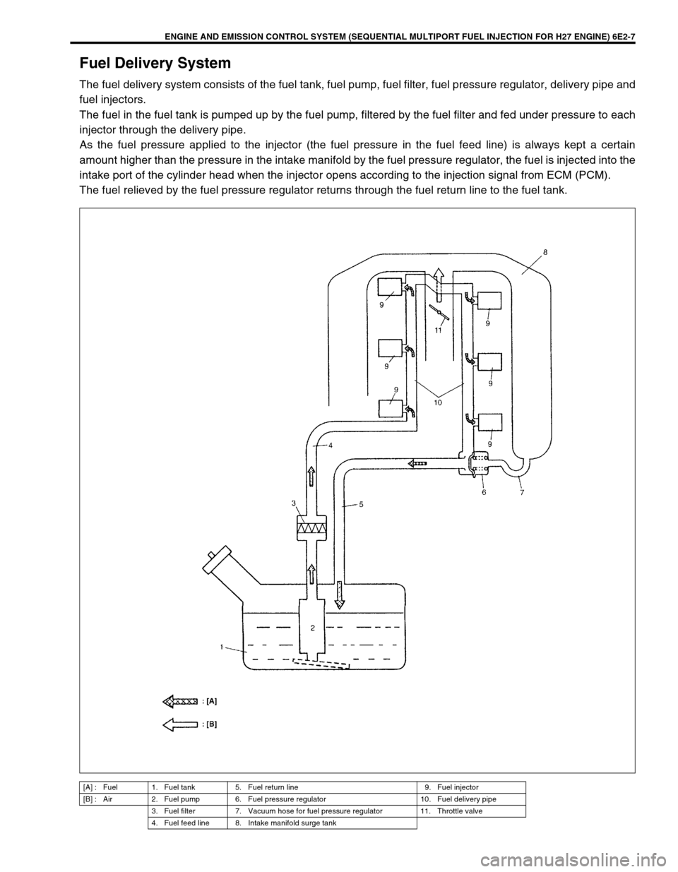
Fuel Delivery System
The fuel delivery system consists of the fuel tank, fuel pump, fuel filter, fuel pressure regulator, delivery pipe and
fuel injectors.
The fuel in the fuel tank is pumped up by the fuel pump, filtered by the fuel filter and fed under pressure to each
injector through the delivery pipe.
As the fuel pressure applied to the injector (the fuel pressure in the fuel feed line) is always kept a certain
amount higher than the pressure in the intake manifold by the fuel pressure regulator, the fuel is injected into the
intake port of the cylinder head when the injector opens according to the injection signal from ECM (PCM).
The fuel relieved by the fuel pressure regulator returns through the fuel return line to the fuel tank.
[A] : Fuel 1. Fuel tank 5. Fuel return line 9. Fuel injector
[B] : Air 2. Fuel pump 6. Fuel pressure regulator 10. Fuel delivery pipe
3. Fuel filter 7. Vacuum hose for fuel pressure regulator 11. Throttle valve
4. Fuel feed line 8. Intake manifold surge tank
Page 341 of 656
6E2-8 ENGINE AND EMISSION CONTROL SYSTEM (SEQUENTIAL MULTIPORT FUEL INJECTION FOR H27 ENGINE)
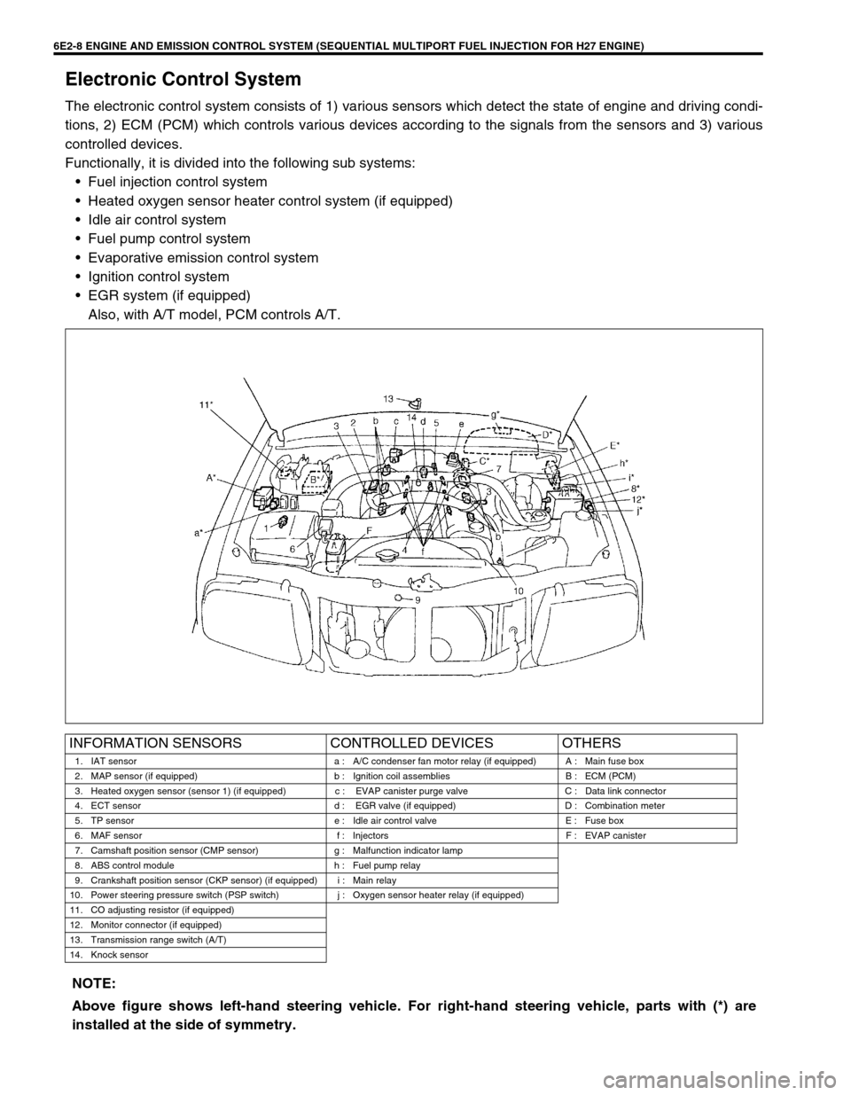
Electronic Control System
The electronic control system consists of 1) various sensors which detect the state of engine and driving condi-
tions, 2) ECM (PCM) which controls various devices according to the signals from the sensors and 3) various
controlled devices.
Functionally, it is divided into the following sub systems:
•Fuel injection control system
•Heated oxygen sensor heater control system (if equipped)
•Idle air control system
•Fuel pump control system
•Evaporative emission control system
•Ignition control system
•EGR system (if equipped)
Also, with A/T model, PCM controls A/T.
INFORMATION SENSORS CONTROLLED DEVICES OTHERS
1. IAT sensor a : A/C condenser fan motor relay (if equipped) A : Main fuse box
2. MAP sensor (if equipped) b : Ignition coil assemblies B : ECM (PCM)
3. Heated oxygen sensor (sensor 1) (if equipped) c : EVAP canister purge valve C : Data link connector
4. ECT sensor d : EGR valve (if equipped) D : Combination meter
5. TP sensor e : Idle air control valve E : Fuse box
6. MAF sensor f : Injectors F : EVAP canister
7. Camshaft position sensor (CMP sensor) g : Malfunction indicator lamp
8. ABS control module h : Fuel pump relay
9. Crankshaft position sensor (CKP sensor) (if equipped) i : Main relay
10. Power steering pressure switch (PSP switch) j : Oxygen sensor heater relay (if equipped)
11. CO adjusting resistor (if equipped)
12. Monitor connector (if equipped)
13. Transmission range switch (A/T)
14. Knock sensor
NOTE:
Above figure shows left-hand steering vehicle. For right-hand steering vehicle, parts with (*) are
installed at the side of symmetry.
Page 343 of 656
6E2-10 ENGINE AND EMISSION CONTROL SYSTEM (SEQUENTIAL MULTIPORT FUEL INJECTION FOR H27 ENGINE)
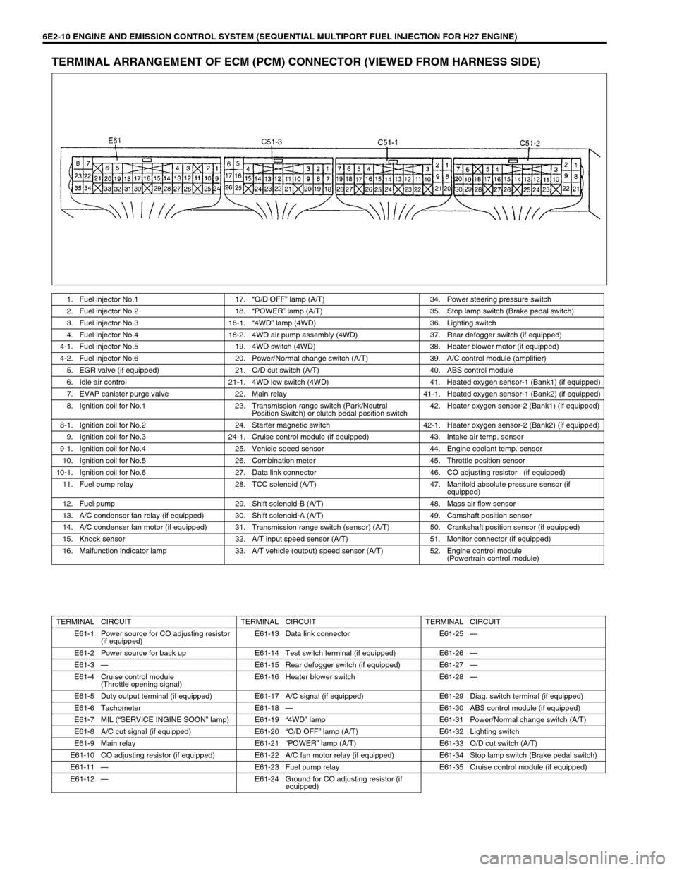
TERMINAL ARRANGEMENT OF ECM (PCM) CONNECTOR (VIEWED FROM HARNESS SIDE)
1. Fuel injector No.1 17.“O/D OFF” lamp (A/T) 34. Power steering pressure switch
2. Fuel injector No.2 18.“POWER” lamp (A/T) 35. Stop lamp switch (Brake pedal switch)
3. Fuel injector No.3 18-1.“4WD” lamp (4WD) 36. Lighting switch
4. Fuel injector No.4 18-2. 4WD air pump assembly (4WD) 37. Rear defogger switch (if equipped)
4-1. Fuel injector No.5 19. 4WD switch (4WD) 38. Heater blower motor (if equipped)
4-2. Fuel injector No.6 20. Power/Normal change switch (A/T) 39. A/C control module (amplifier)
5. EGR valve (if equipped) 21. O/D cut switch (A/T) 40. ABS control module
6. Idle air control 21-1. 4WD low switch (4WD) 41. Heated oxygen sensor-1 (Bank1) (if equipped)
7. EVAP canister purge valve 22. Main relay 41-1. Heated oxygen sensor-1 (Bank2) (if equipped)
8. Ignition coil for No.1 23. Transmission range switch (Park/Neutral
Position Switch) or clutch pedal position switch42. Heater oxygen sensor-2 (Bank1) (if equipped)
8-1. Ignition coil for No.2 24. Starter magnetic switch 42-1. Heater oxygen sensor-2 (Bank2) (if equipped)
9. Ignition coil for No.3 24-1. Cruise control module (if equipped) 43. Intake air temp. sensor
9-1. Ignition coil for No.4 25. Vehicle speed sensor 44. Engine coolant temp. sensor
10. Ignition coil for No.5 26. Combination meter 45. Throttle position sensor
10-1. Ignition coil for No.6 27. Data link connector 46. CO adjusting resistor (if equipped)
11. Fuel pump relay 28. TCC solenoid (A/T) 47. Manifold absolute pressure sensor (if
equipped)
12. Fuel pump 29. Shift solenoid-B (A/T) 48. Mass air flow sensor
13. A/C condenser fan relay (if equipped) 30. Shift solenoid-A (A/T) 49. Camshaft position sensor
14. A/C condenser fan motor (if equipped) 31. Transmission range switch (sensor) (A/T) 50. Crankshaft position sensor (if equipped)
15. Knock sensor 32. A/T input speed sensor (A/T) 51. Monitor connector (if equipped)
16. Malfunction indicator lamp 33. A/T vehicle (output) speed sensor (A/T) 52. Engine control module
(Powertrain control module)
TERMINAL CIRCUIT TERMINAL CIRCUIT TERMINAL CIRCUIT
E61-1 Power source for CO adjusting resistor
(if equipped)E61-13 Data link connector E61-25—
E61-2 Power source for back up E61-14 Test switch terminal (if equipped) E61-26—
E61-3—E61-15 Rear defogger switch (if equipped) E61-27—
E61-4 Cruise control module
(Throttle opening signal)E61-16 Heater blower switch E61-28—
E61-5 Duty output terminal (if equipped) E61-17 A/C signal (if equipped) E61-29 Diag. switch terminal (if equipped)
E61-6 Tachometer E61-18—E61-30 ABS control module (if equipped)
E61-7 MIL (“SERVICE INGINE SOON” lamp) E61-19“4WD” lamp E61-31 Power/Normal change switch (A/T)
E61-8 A/C cut signal (if equipped) E61-20“O/D OFF” lamp (A/T) E61-32 Lighting switch
E61-9 Main relay E61-21“POWER” lamp (A/T) E61-33 O/D cut switch (A/T)
E61-10 CO adjusting resistor (if equipped) E61-22 A/C fan motor relay (if equipped) E61-34 Stop lamp switch (Brake pedal switch)
E61-11—E61-23 Fuel pump relay E61-35 Cruise control module (if equipped)
E61-12—E61-24 Ground for CO adjusting resistor (if
equipped)