4 wheel drive SUZUKI GRAND VITARA 2001 2.G User Guide
[x] Cancel search | Manufacturer: SUZUKI, Model Year: 2001, Model line: GRAND VITARA, Model: SUZUKI GRAND VITARA 2001 2.GPages: 656, PDF Size: 14.31 MB
Page 139 of 656
5E2-14 ANTILOCK BRAKE SYSTEM (ABS)
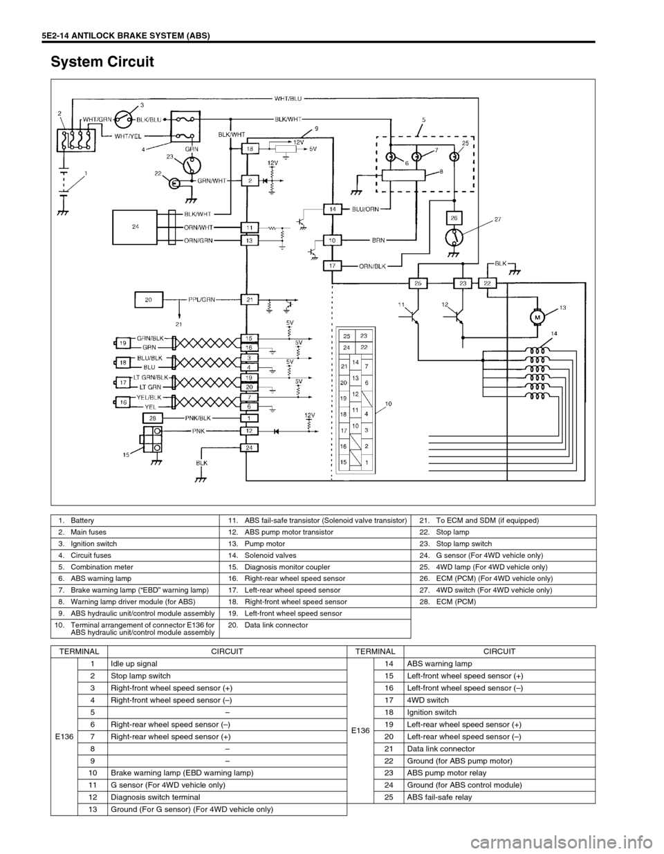
System Circuit
1. Battery 11. ABS fail-safe transistor (Solenoid valve transistor) 21. To ECM and SDM (if equipped)
2. Main fuses 12. ABS pump motor transistor 22. Stop lamp
3. Ignition switch 13. Pump motor 23. Stop lamp switch
4. Circuit fuses 14. Solenoid valves 24. G sensor (For 4WD vehicle only)
5. Combination meter 15. Diagnosis monitor coupler 25. 4WD lamp (For 4WD vehicle only)
6. ABS warning lamp 16. Right-rear wheel speed sensor 26. ECM (PCM) (For 4WD vehicle only)
7. Brake warning lamp (“EBD” warning lamp) 17. Left-rear wheel speed sensor 27. 4WD switch (For 4WD vehicle only)
8. Warning lamp driver module (for ABS) 18. Right-front wheel speed sensor 28. ECM (PCM)
9. ABS hydraulic unit/control module assembly 19. Left-front wheel speed sensor
10. Terminal arrangement of connector E136 for
ABS hydraulic unit/control module assembly20. Data link connector
TERMINAL CIRCUIT TERMINAL CIRCUIT
E1361 Idle up signal
E13614 ABS warning lamp
2 Stop lamp switch 15 Left-front wheel speed sensor (+)
3 Right-front wheel speed sensor (+) 16 Left-front wheel speed sensor (–)
4 Right-front wheel speed sensor (–) 17 4WD switch
5–18 Ignition switch
6 Right-rear wheel speed sensor (–) 19 Left-rear wheel speed sensor (+)
7 Right-rear wheel speed sensor (+) 20 Left-rear wheel speed sensor (–)
8–21 Data link connector
9–22 Ground (for ABS pump motor)
10 Brake warning lamp (EBD warning lamp) 23 ABS pump motor relay
11 G sensor (For 4WD vehicle only) 24 Ground (for ABS control module)
12 Diagnosis switch terminal 25 ABS fail-safe relay
13 Ground (For G sensor) (For 4WD vehicle only)
Page 144 of 656
ANTILOCK BRAKE SYSTEM (ABS) 5E2-19
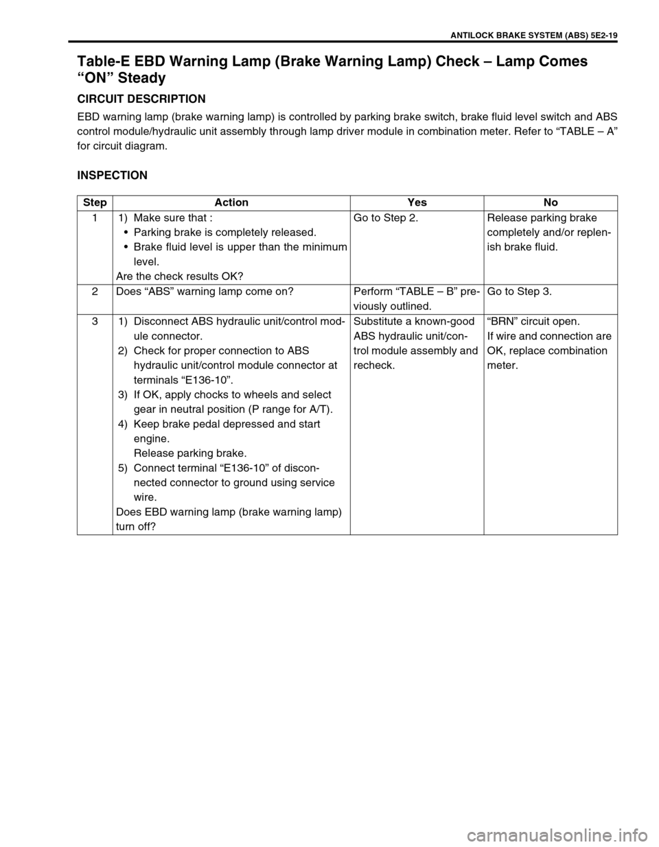
Table-E EBD Warning Lamp (Brake Warning Lamp) Check – Lamp Comes
“ON” Steady
CIRCUIT DESCRIPTION
EBD warning lamp (brake warning lamp) is controlled by parking brake switch, brake fluid level switch and ABS
control module/hydraulic unit assembly through lamp driver module in combination meter. Refer to “TABLE – A”
for circuit diagram.
INSPECTION
Step Action Yes No
1 1) Make sure that :
Parking brake is completely released.
Brake fluid level is upper than the minimum
level.
Are the check results OK?Go to Step 2. Release parking brake
completely and/or replen-
ish brake fluid.
2Does “ABS” warning lamp come on? Perform “TABLE – B” pre-
viously outlined.Go to Step 3.
3 1) Disconnect ABS hydraulic unit/control mod-
ule connector.
2) Check for proper connection to ABS
hydraulic unit/control module connector at
terminals “E136-10”.
3) If OK, apply chocks to wheels and select
gear in neutral position (P range for A/T).
4) Keep brake pedal depressed and start
engine.
Release parking brake.
5) Connect terminal “E136-10” of discon-
nected connector to ground using service
wire.
Does EBD warning lamp (brake warning lamp)
turn off?Substitute a known-good
ABS hydraulic unit/con-
trol module assembly and
recheck.“BRN” circuit open.
If wire and connection are
OK, replace combination
meter.
Page 147 of 656
5E2-22 ANTILOCK BRAKE SYSTEM (ABS)
DTC C1021 (DTC 21), DTC C1022 (DTC 22) – Right-Front Wheel Speed Sensor
Circuit or Sensor Ring
DTC C1025 (DTC 25), DTC C1026 (DTC 26) – Left-Front Wheel Speed Sensor
Circuit or Sensor Ring
DTC C1031 (DTC 31), DTC C1032 (DTC 32) – Right-Rear Wheel Speed Sensor
Circuit or Sensor Ring
DTC C1035 (DTC 35), DTC C1036 (DTC 36) – Left-Rear Wheel Speed Sensor
Circuit or Sensor Ring
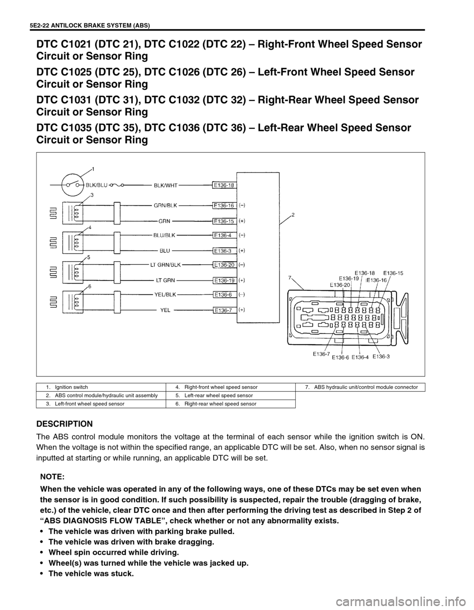
DESCRIPTION
The ABS control module monitors the voltage at the terminal of each sensor while the ignition switch is ON.
When the voltage is not within the specified range, an applicable DTC will be set. Also, when no sensor signal is
inputted at starting or while running, an applicable DTC will be set.
1. Ignition switch 4. Right-front wheel speed sensor 7. ABS hydraulic unit/control module connector
2. ABS control module/hydraulic unit assembly 5. Left-rear wheel speed sensor
3. Left-front wheel speed sensor 6. Right-rear wheel speed sensor
NOTE:
When the vehicle was operated in any of the following ways, one of these DTCs may be set even when
the sensor is in good condition. If such possibility is suspected, repair the trouble (dragging of brake,
etc.) of the vehicle, clear DTC once and then after performing the driving test as described in Step 2 of
“ABS DIAGNOSIS FLOW TABLE”, check whether or not any abnormality exists.
The vehicle was driven with parking brake pulled.
The vehicle was driven with brake dragging.
Wheel spin occurred while driving.
Wheel(s) was turned while the vehicle was jacked up.
The vehicle was stuck.
Page 166 of 656
ENGINE GENERAL INFORMATION AND DIAGNOSIS (H27 ENGINE) 6-1-5
Fuel Pressure Relief Procedure
After making sure that engine is cold, relief fuel pressure as fol-
lows.
1) Place transmission gear shift lever in “Neutral” (shift selector
lever to “P” range for A/T vehicle), set parking brake, and
block drive wheels.
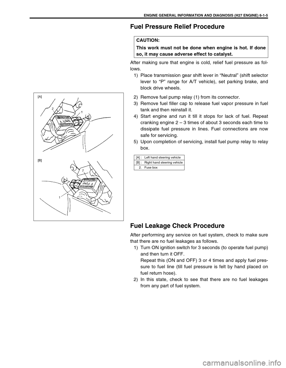
2) Remove fuel pump relay (1) from its connector.
3) Remove fuel filler cap to release fuel vapor pressure in fuel
tank and then reinstall it.
4) Start engine and run it till it stops for lack of fuel. Repeat
cranking engine 2 – 3 times of about 3 seconds each time to
dissipate fuel pressure in lines. Fuel connections are now
safe for servicing.
5) Upon completion of servicing, install fuel pump relay to relay
box.
Fuel Leakage Check Procedure
After performing any service on fuel system, check to make sure
that there are no fuel leakages as follows.
1) Turn ON ignition switch for 3 seconds (to operate fuel pump)
and then turn it OFF.
Repeat this (ON and OFF) 3 or 4 times and apply fuel pres-
sure to fuel line (till fuel pressure is felt by hand placed on
fuel return hose).
2) In this state, check to see that there are no fuel leakages
from any part of fuel system. CAUTION:
This work must not be done when engine is hot. If done
so, it may cause adverse effect to catalyst.
[A] : Left hand steering vehicle
[B] : Right hand steering vehicle
2. Fuse box
Page 307 of 656
6A2-20 ENGINE MECHANICAL (H27 ENGINE)
12) Install oil pan and oil pump strainer.
Refer to “OIL PAN AND OIL PUMP STRAINER” in this sec-
tion.
13) Install cylinder head cover.
Refer to “CYLINDER HEAD COVER” in this section.
14) Install exhaust manifold.
Refer to “EXHAUST MANIFOLD” in this section.
15) Install radiator outlet pipe, radiator, cooling fan and water
hose.
Refer to “COOLING WATER PIPES OR HOSES”, “RADIA-
TOR” and “COOLING FAN AND FAN CLUTCH” in Section
6B.
16) Install throttle body and intake manifold.
Refer to “THROTTLE BODY AND INTAKE MANIFOLD” in
this section.
17) Adjust water pump drive belt tension.
Refer to “COOLING FAN BELT TENSION CHECK AND
ADJUSTMENT” in Section 6B.
18) Adjust power steering pump drive belt tension.
Refer to “POWER STEERING PUMP DRIVE BELT” in Sec-
tion 3B1.
19) Adjust accelerator cable play and A/T throttle cable play.
Refer to “ACCELERATOR CABLE ADJUSTMENT” and “A/T
THROTTLE CABLE ADJUSTMENT (A/T VEHICLE)” in Sec-
tion 6E2.
20) Check to ensure that all removed parts are back in place.
Reinstall any necessary parts which have not been rein-
stalled.
21) Refill engine with engine oil, referring to “ENGINE OIL
CHANGE” in Section 0B.
22) Refill cooling system referring to “COOLING SYSTEM
FLUSH AND REFILL” in Section 6B.
23) Refill front differential housing with gear oil if drained, refer-
ring to “MAINTENANCE SERVICE” in Section 7E.
24) Connect negative cable at battery.
25) Check ignition timing and adjust as necessary, referring to
“IGNITION TIMING CHECK AND ADJUSTMENT” in Section
6F2.
26) Verify that there is no fuel leakage, water leakage, oil leak-
age and exhaust gas leakage at each connection.
27) Check wheel alignment, referring to “STEERING ANGLE” in
Section 3A.
Page 317 of 656

6A2-30 ENGINE MECHANICAL (H27 ENGINE)
Main Bearings, Crankshaft and Cylinder Block
1. Cylinder block 6. Rear oil seal 11. O-ring [A]: Sealant application amount
2. Lower crankcase :
Apply sealant 99000-31150 to lower
crankcase mating surface.7. Flywheel (M/T) Drive plate
(A/T)12. Clutch housing plate Tightening Torque
3. Crankshaft 8. Water pump 13. Cap bolt Do not reuse
4. Main bearing 9. O-ring 14. Lower crankcase bolt Apply engine oil to sliding
surface of each parts.
5. Thrust bearing :
Set bearing facing grooved side to
crank weds.10. Timing chain oil jet 15. Knock sensor“a”: Width 3 mm (0.12 in.)
“b”: Height 2 mm (0.08 in.)
Page 348 of 656
ENGINE AND EMISSION CONTROL SYSTEM (SEQUENTIAL MULTIPORT FUEL INJECTION FOR H27 ENGINE) 6E2-15
Idle Speed/Idle Air Control (IAC) Duty Inspec-
tion
Before idle speed/IAC duty check, make sure of the following.
•Lead wires and hoses of engine/emission control systems
are connected securely.
•Accelerator cable is adjusted.
•Ignition timing is within specification.
•All accessories (wipers, heater, lights, A/C, etc.) are out of
service.
•Air cleaner has been properly installed and is in good condi-
tion.
•ECM (PCM) does not detect any malfunction DTC.
After above items are all confirmed, check idle speed and IAC
duty as follows.
[Using SUZUKI scan tool]
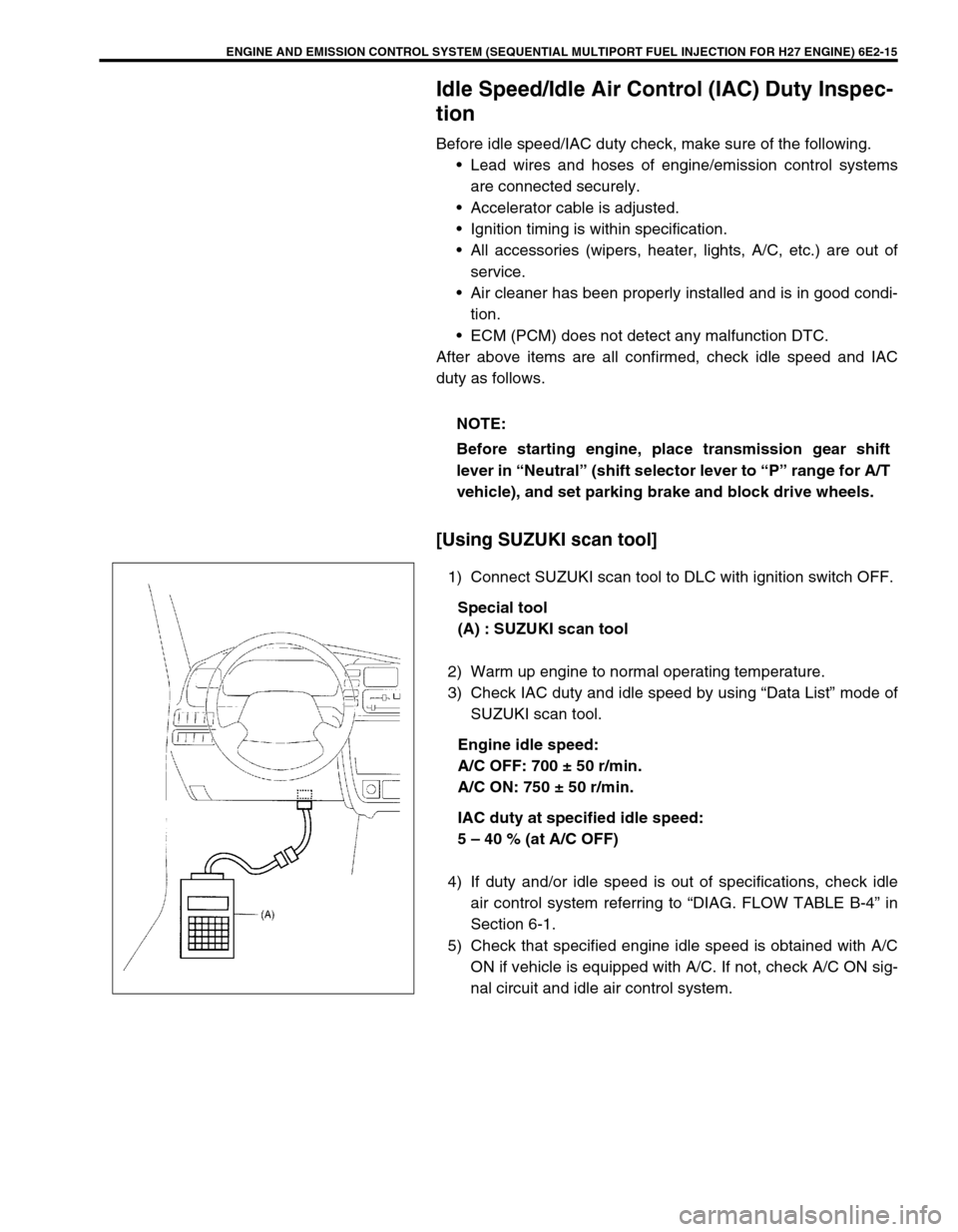
1) Connect SUZUKI scan tool to DLC with ignition switch OFF.
Special tool
(A) : SUZUKI scan tool
2) Warm up engine to normal operating temperature.
3) Check IAC duty and idle speed by using “Data List” mode of
SUZUKI scan tool.
Engine idle speed:
A/C OFF: 700 ± 50 r/min.
A/C ON: 750 ± 50 r/min.
IAC duty at specified idle speed:
5 – 40 % (at A/C OFF)
4) If duty and/or idle speed is out of specifications, check idle
air control system referring to “DIAG. FLOW TABLE B-4” in
Section 6-1.
5) Check that specified engine idle speed is obtained with A/C
ON if vehicle is equipped with A/C. If not, check A/C ON sig-
nal circuit and idle air control system. NOTE:
Before starting engine, place transmission gear shift
lever in “Neutral” (shift selector lever to “P” range for A/T
vehicle), and set parking brake and block drive wheels.
Page 450 of 656
AUTOMATIC TRANSMISSION (4 A/T) 7B1-41
Manual Road Test
This test check the gear being used in “L”, “2” or “D” range when
driven with unoperated gear shift control system. Test drive vehi-
cle on a level road.
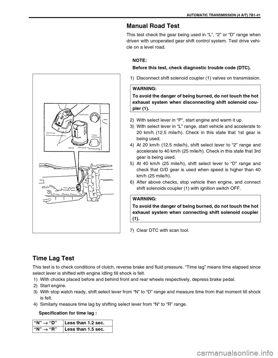
1) Disconnect shift solenoid coupler (1) valves on transmission.
2) With select lever in “P”, start engine and warm it up.
3) With select lever in “L” range, start vehicle and accelerate to
20 km/h (12.5 mile/h). Check in this state that 1st gear is
being used.
4) At 20 km/h (12.5 mile/h), shift select lever to “2” range and
accelerate to 40 km/h (25 mile/h). Check in this state that 3rd
gear is being used.
5) At 40 km/h (25 mile/h), shift select lever to “D” range and
check that O/D gear is used when speed is higher than 40
km/h (25 mile/h).
6) After above checks, stop vehicle then engine, and connect
shift solenoids coupler (1) with ignition switch OFF.
7) Clear DTC with scan tool.
Time Lag Test
This test is to check conditions of clutch, reverse brake and fluid pressure. “Time lag” means time elapsed since
select lever is shifted with engine idling till shock is felt.
1) With chocks placed before and behind front and rear wheels respectively, depress brake pedal.
2) Start engine.
3) With stop watch ready, shift select lever from “N” to “D” range and measure time from that moment till shock
is felt.
4) Similarly measure time lag by shifting select lever from “N“ to “R” range.
Specification for time lag :NOTE:
Before this test, check diagnostic trouble code (DTC).
WARNING:
To avoid the danger of being burned, do not touch the hot
exhaust system when disconnecting shift solenoid cou-
pler (1).
WARNING:
To avoid the danger of being burned, do not touch the hot
exhaust system when connecting shift solenoid coupler
(1).
“N” →
→→ → “D”Less than 1.2 sec.
“N” →
→→ → “R”Less than 1.5 sec.
Page 452 of 656
AUTOMATIC TRANSMISSION (4 A/T) 7B1-43
On-Vehicle Service
Maintenance Service
Fluid level
LEVEL CHECK AT NORMAL OPERATING TEMPERATURE
1) Stop vehicle and place it level.
2) Apply parking brake and place chocks against wheels.
3) With selector at P position, start engine.
4) Warm up engine till fluid temperature reaches normal oper-
ating temperature (70 – 80 °C (158 – 176 °F)). As a guide to
check fluid temperature, warm up engine till engine coolant
temperature meter indicated around 1 unit above “C” point.
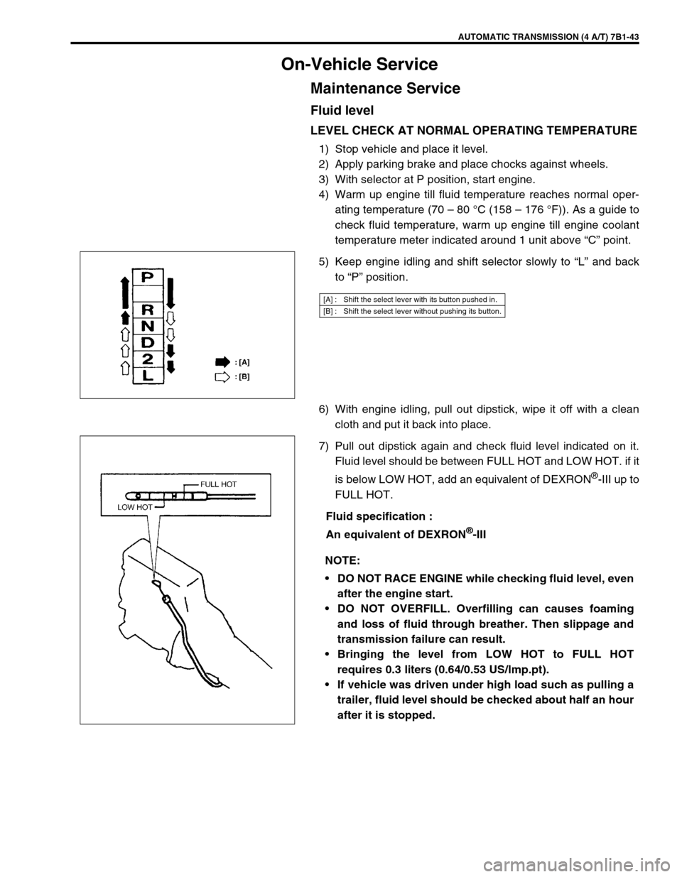
5) Keep engine idling and shift selector slowly to “L” and back
to “P” position.
6) With engine idling, pull out dipstick, wipe it off with a clean
cloth and put it back into place.
7) Pull out dipstick again and check fluid level indicated on it.
Fluid level should be between FULL HOT and LOW HOT. if it
is below LOW HOT, add an equivalent of DEXRON
®-III up to
FULL HOT.
Fluid specification :
An equivalent of DEXRON
®-III
[A] : Shift the select lever with its button pushed in.
[B] : Shift the select lever without pushing its button.
NOTE:
DO NOT RACE ENGINE while checking fluid level, even
after the engine start.
DO NOT OVERFILL. Overfilling can causes foaming
and loss of fluid through breather. Then slippage and
transmission failure can result.
Bringing the level from LOW HOT to FULL HOT
requires 0.3 liters (0.64/0.53 US/lmp.pt).
If vehicle was driven under high load such as pulling a
trailer, fluid level should be checked about half an hour
after it is stopped.
Page 480 of 656
DIFFERENTIAL (FRONT) 7E-7
On-Vehicle Service
Differential Mountings
REMOVAL AND INSTALLATION
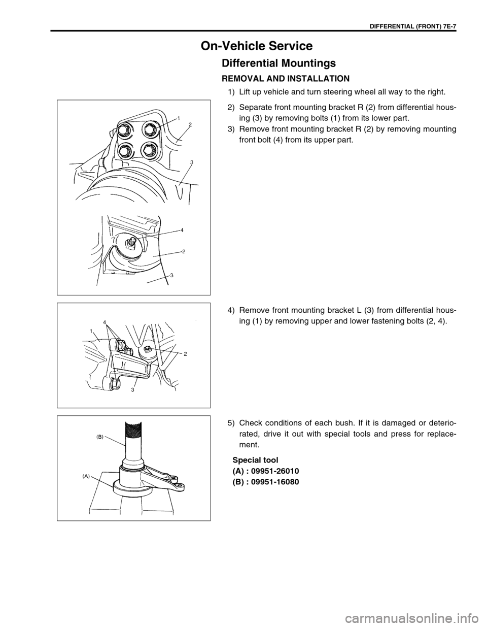
1) Lift up vehicle and turn steering wheel all way to the right.
2) Separate front mounting bracket R (2) from differential hous-
ing (3) by removing bolts (1) from its lower part.
3) Remove front mounting bracket R (2) by removing mounting
front bolt (4) from its upper part.
4) Remove front mounting bracket L (3) from differential hous-
ing (1) by removing upper and lower fastening bolts (2, 4).
5) Check conditions of each bush. If it is damaged or deterio-
rated, drive it out with special tools and press for replace-
ment.
Special tool
(A) : 09951-26010
(B) : 09951-16080