brake light SUZUKI GRAND VITARA 2001 2.G User Guide
[x] Cancel search | Manufacturer: SUZUKI, Model Year: 2001, Model line: GRAND VITARA, Model: SUZUKI GRAND VITARA 2001 2.GPages: 656, PDF Size: 14.31 MB
Page 187 of 656
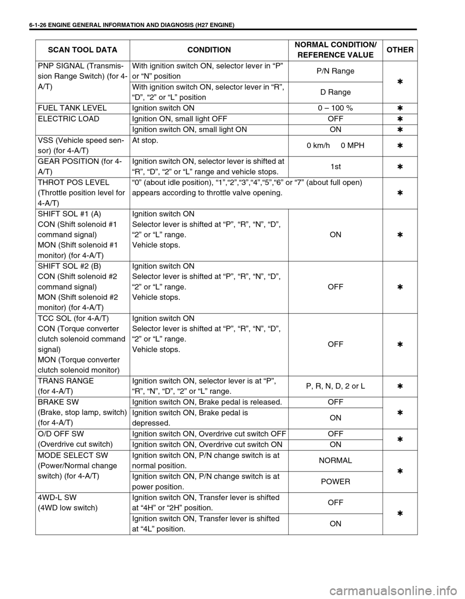
6-1-26 ENGINE GENERAL INFORMATION AND DIAGNOSIS (H27 ENGINE)
PNP SIGNAL (Transmis-
sion Range Switch) (for 4-
A/T)With ignition switch ON, selector lever in “P”
or “N” positionP/N Range
✱
With ignition switch ON, selector lever in “R”,
“D”, “2” or “L” positionD Range
FUEL TANK LEVEL Ignition switch ON 0 – 100 %✱
ELECTRIC LOAD Ignition ON, small light OFF OFF✱
Ignition switch ON, small light ON ON✱
VSS (Vehicle speed sen-
sor) (for 4-A/T)At stop.
0 km/h 0 MPH✱
GEAR POSITION (for 4-
A/T)Ignition switch ON, selector lever is shifted at
“R”, “D”, “2” or “L” range and vehicle stops.1st✱
THROT POS LEVEL
(Throttle position level for
4-A/T)“0” (about idle position), “1”,“2”,“3”,“4”,“5”,“6” or “7” (about full open)
appears according to throttle valve opening.✱
SHIFT SOL #1 (A)
CON (Shift solenoid #1
command signal)
MON (Shift solenoid #1
monitor) (for 4-A/T)Ignition switch ON
Selector lever is shifted at “P”, “R”, “N”, “D”,
“2” or “L” range.
Vehicle stops.ON✱
SHIFT SOL #2 (B)
CON (Shift solenoid #2
command signal)
MON (Shift solenoid #2
monitor) (for 4-A/T)Ignition switch ON
Selector lever is shifted at “P”, “R”, “N”, “D”,
“2” or “L” range.
Vehicle stops.OFF✱
TCC SOL (for 4-A/T)
CON (Torque converter
clutch solenoid command
signal)
MON (Torque converter
clutch solenoid monitor)Ignition switch ON
Selector lever is shifted at “P”, “R”, “N”, “D”,
“2” or “L” range.
Vehicle stops.OFF✱
TRANS RANGE
(for 4-A/T)Ignition switch ON, selector lever is at “P”,
“R”, “N”, “D”, “2” or “L” range.P, R, N, D, 2 or L✱
BRAKE SW
(Brake, stop lamp, switch)
(for 4-A/T)Ignition switch ON, Brake pedal is released. OFF
✱
Ignition switch ON, Brake pedal is
depressed.ON
O/D OFF SW
(Overdrive cut switch)Ignition switch ON, Overdrive cut switch OFF OFF
✱
Ignition switch ON, Overdrive cut switch ON ON
MODE SELECT SW
(Power/Normal change
switch) (for 4-A/T)Ignition switch ON, P/N change switch is at
normal position.NORMAL
✱
Ignition switch ON, P/N change switch is at
power position.POWER
4WD-L SW
(4WD low switch)Ignition switch ON, Transfer lever is shifted
at “4H” or “2H” position.OFF
✱
Ignition switch ON, Transfer lever is shifted
at “4L” position.ON SCAN TOOL DATA CONDITIONNORMAL CONDITION/
REFERENCE VALUEOTHER
Page 199 of 656
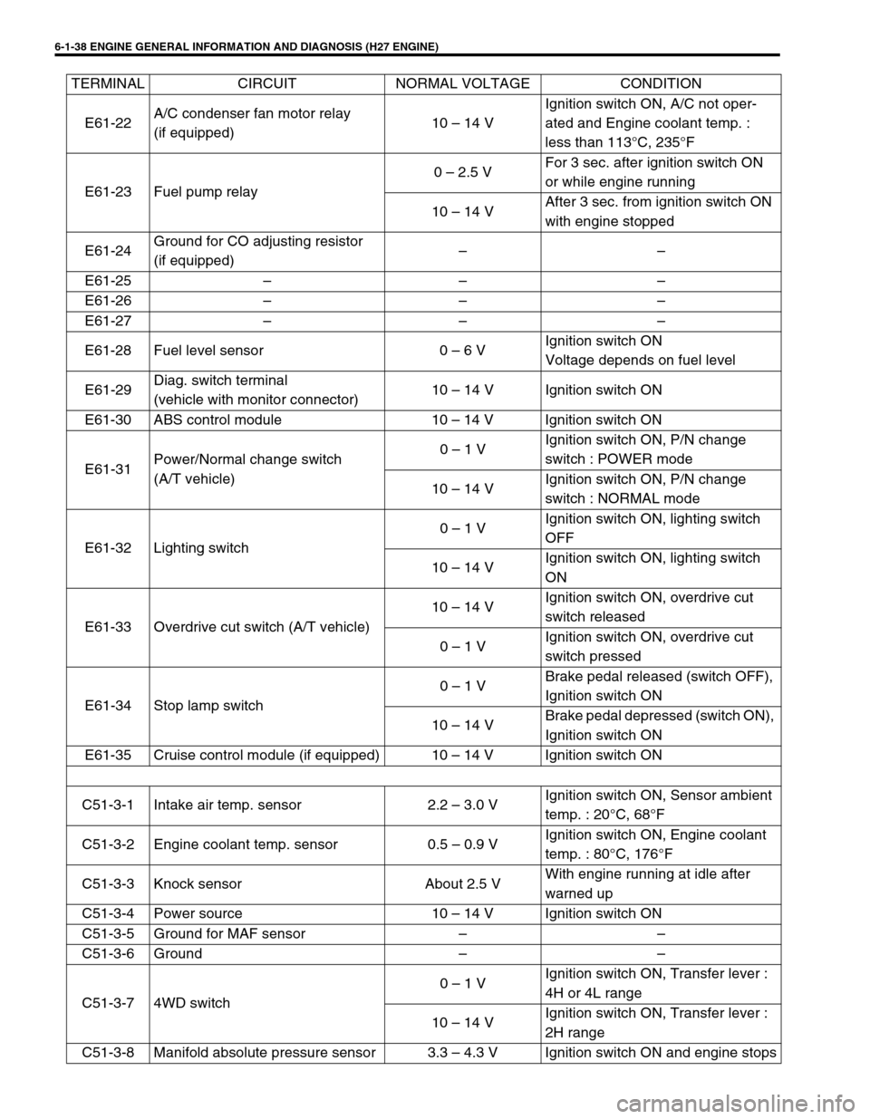
6-1-38 ENGINE GENERAL INFORMATION AND DIAGNOSIS (H27 ENGINE)
E61-22A/C condenser fan motor relay
(if equipped)10 – 14 VIgnition switch ON, A/C not oper-
ated and Engine coolant temp. :
less than 113°C, 235°F
E61-23 Fuel pump relay0 – 2.5 VFor 3 sec. after ignition switch ON
or while engine running
10 – 14 VAfter 3 sec. from ignition switch ON
with engine stopped
E61-24Ground for CO adjusting resistor
(if equipped)––
E61-25 – – –
E61-26 – – –
E61-27 – – –
E61-28 Fuel level sensor 0 – 6 VIgnition switch ON
Voltage depends on fuel level
E61-29Diag. switch terminal
(vehicle with monitor connector)10 – 14 V Ignition switch ON
E61-30 ABS control module 10 – 14 V Ignition switch ON
E61-31Power/Normal change switch
(A/T vehicle)0 – 1 VIgnition switch ON, P/N change
switch : POWER mode
10 – 14 VIgnition switch ON, P/N change
switch : NORMAL mode
E61-32 Lighting switch0 – 1 VIgnition switch ON, lighting switch
OFF
10 – 14 VIgnition switch ON, lighting switch
ON
E61-33 Overdrive cut switch (A/T vehicle)10 – 14 VIgnition switch ON, overdrive cut
switch released
0 – 1 VIgnition switch ON, overdrive cut
switch pressed
E61-34 Stop lamp switch0 – 1 VBrake pedal released (switch OFF),
Ignition switch ON
10 – 14 VBrake pedal depressed (switch ON),
Ignition switch ON
E61-35 Cruise control module (if equipped) 10 – 14 V Ignition switch ON
C51-3-1 Intake air temp. sensor 2.2 – 3.0 VIgnition switch ON, Sensor ambient
temp. : 20°C, 68°F
C51-3-2 Engine coolant temp. sensor 0.5 – 0.9 VIgnition switch ON, Engine coolant
temp. : 80°C, 176°F
C51-3-3 Knock sensor About 2.5 VWith engine running at idle after
warned up
C51-3-4 Power source 10 – 14 V Ignition switch ON
C51-3-5 Ground for MAF sensor – –
C51-3-6 Ground – –
C51-3-7 4WD switch0 – 1 VIgnition switch ON, Transfer lever :
4H or 4L range
10 – 14 VIgnition switch ON, Transfer lever :
2H range
C51-3-8 Manifold absolute pressure sensor 3.3 – 4.3 V Ignition switch ON and engine stops TERMINAL CIRCUIT NORMAL VOLTAGE CONDITION
Page 343 of 656
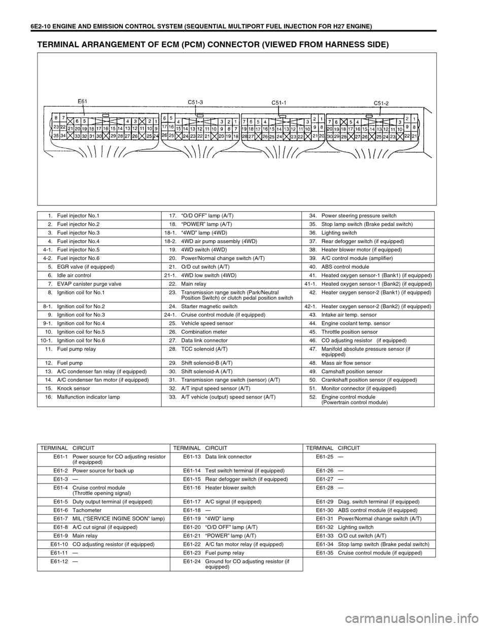
6E2-10 ENGINE AND EMISSION CONTROL SYSTEM (SEQUENTIAL MULTIPORT FUEL INJECTION FOR H27 ENGINE)
TERMINAL ARRANGEMENT OF ECM (PCM) CONNECTOR (VIEWED FROM HARNESS SIDE)
1. Fuel injector No.1 17.“O/D OFF” lamp (A/T) 34. Power steering pressure switch
2. Fuel injector No.2 18.“POWER” lamp (A/T) 35. Stop lamp switch (Brake pedal switch)
3. Fuel injector No.3 18-1.“4WD” lamp (4WD) 36. Lighting switch
4. Fuel injector No.4 18-2. 4WD air pump assembly (4WD) 37. Rear defogger switch (if equipped)
4-1. Fuel injector No.5 19. 4WD switch (4WD) 38. Heater blower motor (if equipped)
4-2. Fuel injector No.6 20. Power/Normal change switch (A/T) 39. A/C control module (amplifier)
5. EGR valve (if equipped) 21. O/D cut switch (A/T) 40. ABS control module
6. Idle air control 21-1. 4WD low switch (4WD) 41. Heated oxygen sensor-1 (Bank1) (if equipped)
7. EVAP canister purge valve 22. Main relay 41-1. Heated oxygen sensor-1 (Bank2) (if equipped)
8. Ignition coil for No.1 23. Transmission range switch (Park/Neutral
Position Switch) or clutch pedal position switch42. Heater oxygen sensor-2 (Bank1) (if equipped)
8-1. Ignition coil for No.2 24. Starter magnetic switch 42-1. Heater oxygen sensor-2 (Bank2) (if equipped)
9. Ignition coil for No.3 24-1. Cruise control module (if equipped) 43. Intake air temp. sensor
9-1. Ignition coil for No.4 25. Vehicle speed sensor 44. Engine coolant temp. sensor
10. Ignition coil for No.5 26. Combination meter 45. Throttle position sensor
10-1. Ignition coil for No.6 27. Data link connector 46. CO adjusting resistor (if equipped)
11. Fuel pump relay 28. TCC solenoid (A/T) 47. Manifold absolute pressure sensor (if
equipped)
12. Fuel pump 29. Shift solenoid-B (A/T) 48. Mass air flow sensor
13. A/C condenser fan relay (if equipped) 30. Shift solenoid-A (A/T) 49. Camshaft position sensor
14. A/C condenser fan motor (if equipped) 31. Transmission range switch (sensor) (A/T) 50. Crankshaft position sensor (if equipped)
15. Knock sensor 32. A/T input speed sensor (A/T) 51. Monitor connector (if equipped)
16. Malfunction indicator lamp 33. A/T vehicle (output) speed sensor (A/T) 52. Engine control module
(Powertrain control module)
TERMINAL CIRCUIT TERMINAL CIRCUIT TERMINAL CIRCUIT
E61-1 Power source for CO adjusting resistor
(if equipped)E61-13 Data link connector E61-25—
E61-2 Power source for back up E61-14 Test switch terminal (if equipped) E61-26—
E61-3—E61-15 Rear defogger switch (if equipped) E61-27—
E61-4 Cruise control module
(Throttle opening signal)E61-16 Heater blower switch E61-28—
E61-5 Duty output terminal (if equipped) E61-17 A/C signal (if equipped) E61-29 Diag. switch terminal (if equipped)
E61-6 Tachometer E61-18—E61-30 ABS control module (if equipped)
E61-7 MIL (“SERVICE INGINE SOON” lamp) E61-19“4WD” lamp E61-31 Power/Normal change switch (A/T)
E61-8 A/C cut signal (if equipped) E61-20“O/D OFF” lamp (A/T) E61-32 Lighting switch
E61-9 Main relay E61-21“POWER” lamp (A/T) E61-33 O/D cut switch (A/T)
E61-10 CO adjusting resistor (if equipped) E61-22 A/C fan motor relay (if equipped) E61-34 Stop lamp switch (Brake pedal switch)
E61-11—E61-23 Fuel pump relay E61-35 Cruise control module (if equipped)
E61-12—E61-24 Ground for CO adjusting resistor (if
equipped)
Page 345 of 656
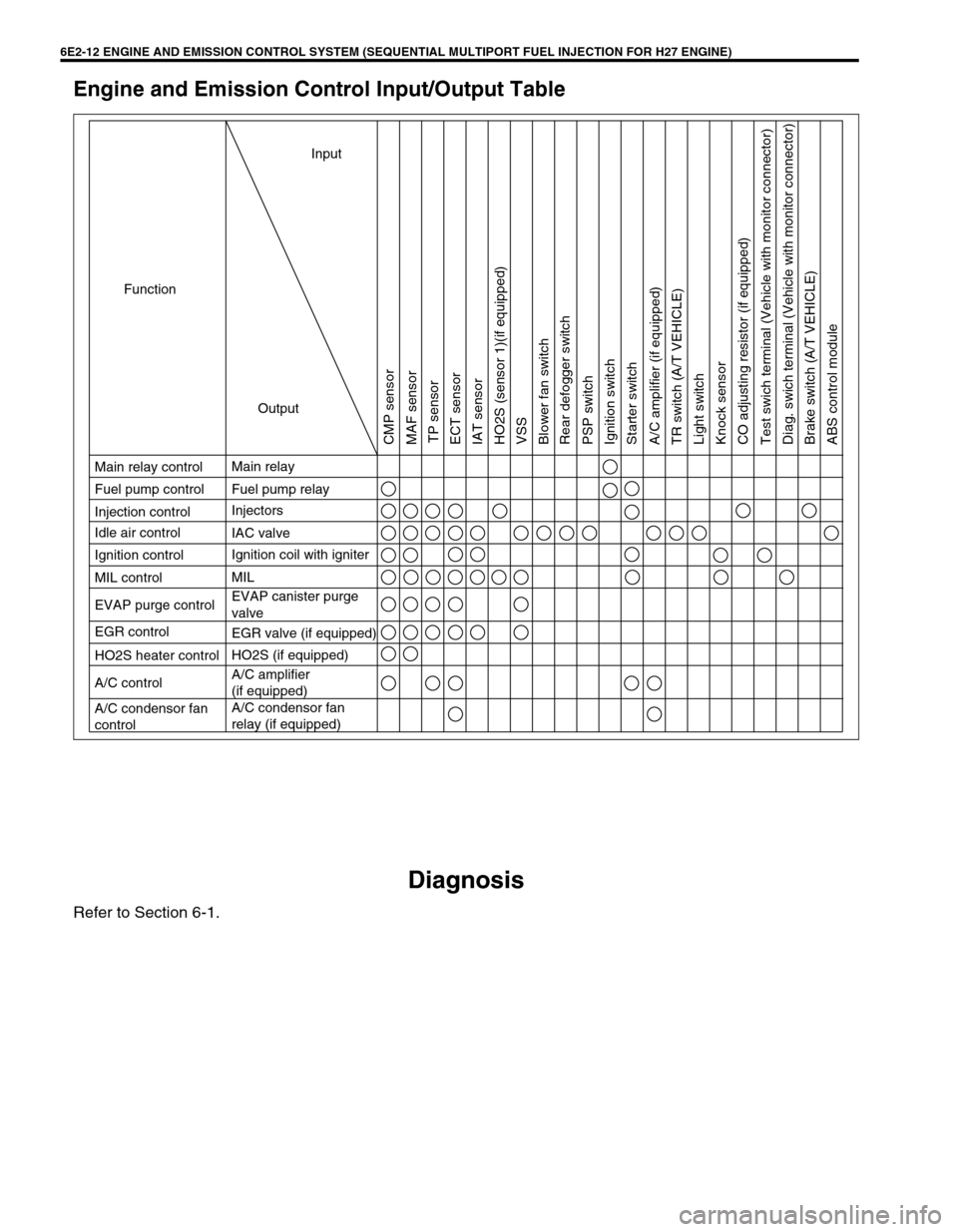
6E2-12 ENGINE AND EMISSION CONTROL SYSTEM (SEQUENTIAL MULTIPORT FUEL INJECTION FOR H27 ENGINE)
Engine and Emission Control Input/Output Table
Diagnosis
Refer to Section 6-1.
Ignition coil with igniter
HO2S heater control
Input
Output Function
Main relay control
Fuel pump control
Injection control
Ignition control
MIL control Idle air control
EVAP purge control
EGR control
A/C control
A/C condensor fan
controlMain relay
Fuel pump relay
Injectors
MIL
EVAP canister purge
valve IAC valve
EGR valve (if equipped)
HO2S (if equipped)
A/C amplifier
(if equipped)
A/C condensor fan
relay (if equipped)
CMP sensor
MAF sensor
TP sensor
ECT sensor
IAT sensor
HO2S (sensor 1)(if equipped)
VSS
Blower fan switch
Rear defogger switch
PSP switch
Ignition switch
Starter switch
A/C amplifier (if equipped)
TR switch (A/T VEHICLE)
Light switch
Knock sensor
CO adjusting resistor (if equipped)
Test swich terminal (Vehicle with monitor connector)
Diag. swich terminal (Vehicle with monitor connector)
Brake switch (A/T VEHICLE)
ABS control module
Page 348 of 656
ENGINE AND EMISSION CONTROL SYSTEM (SEQUENTIAL MULTIPORT FUEL INJECTION FOR H27 ENGINE) 6E2-15
Idle Speed/Idle Air Control (IAC) Duty Inspec-
tion
Before idle speed/IAC duty check, make sure of the following.
•Lead wires and hoses of engine/emission control systems
are connected securely.
•Accelerator cable is adjusted.
•Ignition timing is within specification.
•All accessories (wipers, heater, lights, A/C, etc.) are out of
service.
•Air cleaner has been properly installed and is in good condi-
tion.
•ECM (PCM) does not detect any malfunction DTC.
After above items are all confirmed, check idle speed and IAC
duty as follows.
[Using SUZUKI scan tool]
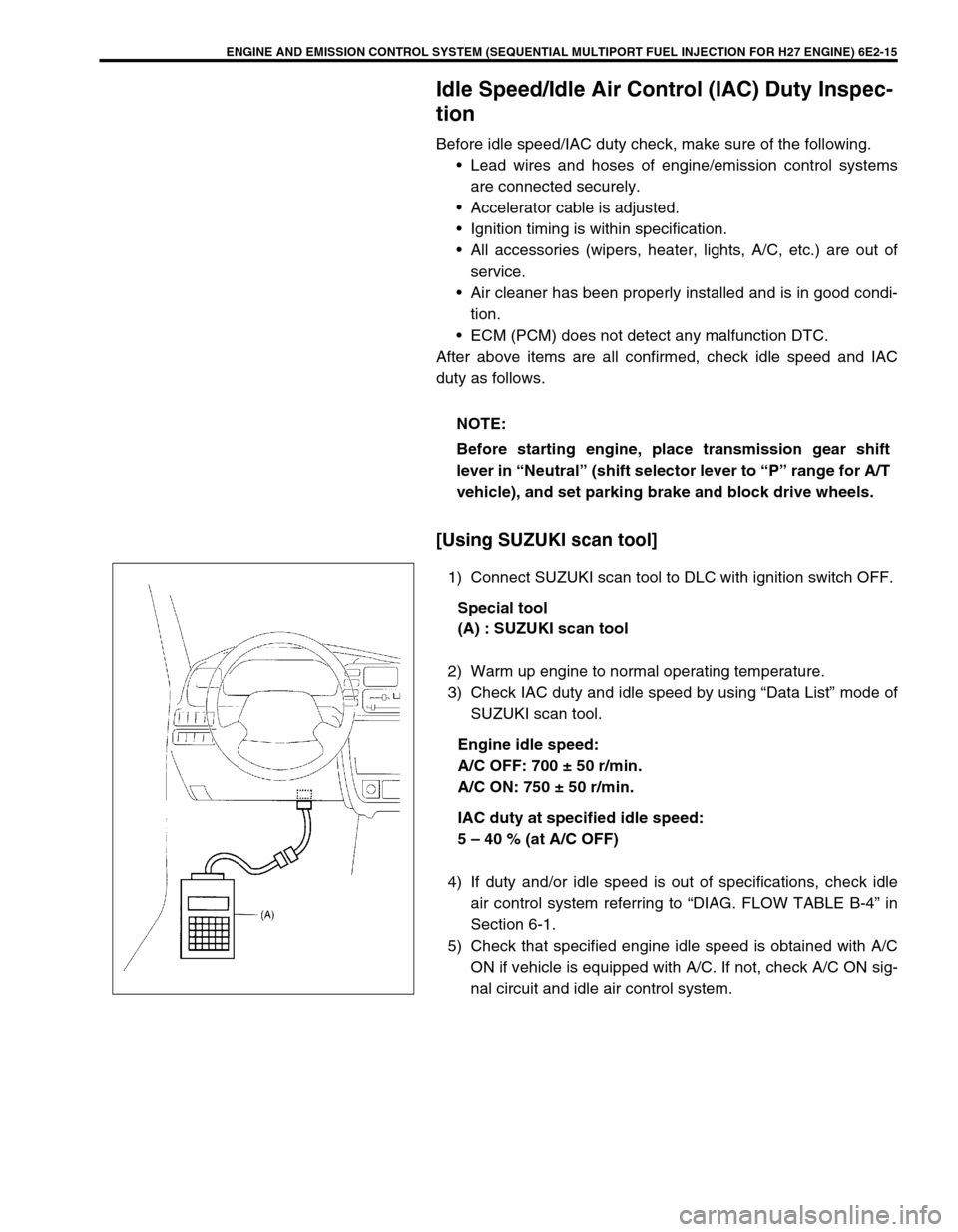
1) Connect SUZUKI scan tool to DLC with ignition switch OFF.
Special tool
(A) : SUZUKI scan tool
2) Warm up engine to normal operating temperature.
3) Check IAC duty and idle speed by using “Data List” mode of
SUZUKI scan tool.
Engine idle speed:
A/C OFF: 700 ± 50 r/min.
A/C ON: 750 ± 50 r/min.
IAC duty at specified idle speed:
5 – 40 % (at A/C OFF)
4) If duty and/or idle speed is out of specifications, check idle
air control system referring to “DIAG. FLOW TABLE B-4” in
Section 6-1.
5) Check that specified engine idle speed is obtained with A/C
ON if vehicle is equipped with A/C. If not, check A/C ON sig-
nal circuit and idle air control system. NOTE:
Before starting engine, place transmission gear shift
lever in “Neutral” (shift selector lever to “P” range for A/T
vehicle), and set parking brake and block drive wheels.
Page 512 of 656
INSTRUMENTATION/DRIVER INFORMATION 8C-1
8C
SECTION 8C
INSTRUMENTATION/DRIVER INFORMATION
CONTENTS
General Description ........................................8C-2
Combination Meter ........................................8C-2
On-vehicle Service ..........................................8C-4
Fuel Meter/Fuel Gauge Unit ..........................8C-4
Fuel level sensor (sender gauge) ..............8C-4
Engine Coolant Temperature (ECT) Meter
and Sensor ....................................................8C-5Engine coolant temperature sensor .......... 8C-5
Oil Pressure Light ......................................... 8C-5
Oil pressure switch .................................... 8C-5
Brake Warning Light ..................................... 8C-5
Brake fluid level switch .............................. 8C-5
WARNING:
For vehicles equipped with Supplemental Restraint (Air Bag) System:
Service on and around the air bag system components or wiring must be performed only by an
authorized SUZUKI dealer. Refer to “Air Bag System Components and Wiring Location View” under
“General Description” in air bag system section in order to confirm whether you are performing ser-
vice on or near the air bag system components or wiring. Please observe all WARNINGS and “Ser-
vice Precautions” under “On-Vehicle Service” in air bag system section before performing service
on or around the air bag system components or wiring. Failure to follow WARNINGS could result in
unintentional activation of the system or could render the system inoperative. Either of these two
conditions may result in severe injury.
Technical service work must be started at least 90 seconds after the ignition switch is turned to the
“LOCK” position and the negative cable is disconnected from the battery. Otherwise, the system
may be activated by reserve energy in the Sensing and Diagnostic Module (SDM).
NOTE:
For the descriptions (items) not found in this section, refer to the same section of the Service Manual
mentioned in the FOREWORD of this manual.
Page 513 of 656
8C-2 INSTRUMENTATION/DRIVER INFORMATION
General Description
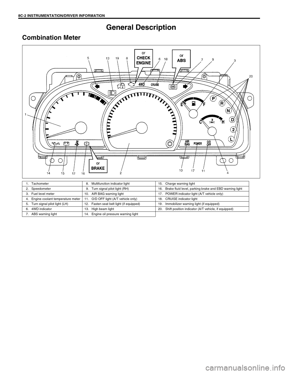
Combination Meter
1. Tachometer 8. Multifunction indicator light 15. Charge warning light
2. Speedometer 9. Turn signal pilot light (RH) 16. Brake fluid level, parking brake and EBD warning light
3. Fuel level meter 10. AIR BAG warning light 17. POWER indicator light (A/T vehicle only)
4. Engine coolant temperature meter 11. O/D OFF light (A/T vehicle only) 18. CRUISE indicator light
5. Turn signal pilot light (LH) 12. Fasten seat belt light (if equipped) 19. Immobilizer warning light (if equipped)
6. 4WD indicator 13. High beam light 20. Shift position indicator (A/T vehicle, if equipped)
7. ABS warning light 14. Engine oil pressure warning light
Page 516 of 656
INSTRUMENTATION/DRIVER INFORMATION 8C-5
Engine Coolant Temperature (ECT) Meter and
Sensor
Engine coolant temperature sensor
REMOVAL AND INSTALLATION
Refer to “ECT SENSOR” in Section 6E2.
Oil Pressure Light
Oil pressure switch
REMOVAL AND INSTALLATION
Refer to “OIL PRESSURE CHECK” in Section 6A2.
Brake Warning Light
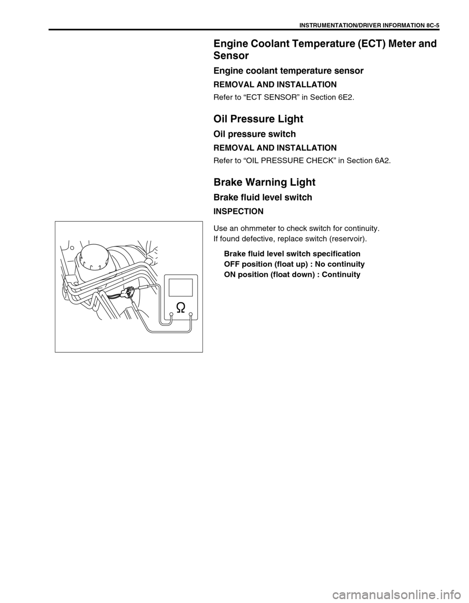
Brake fluid level switch
INSPECTION
Use an ohmmeter to check switch for continuity.
If found defective, replace switch (reservoir).
Brake fluid level switch specification
OFF position (float up) : No continuity
ON position (float down) : Continuity
Page 524 of 656
CRUISE CONTROL SYSTEM 8E-3
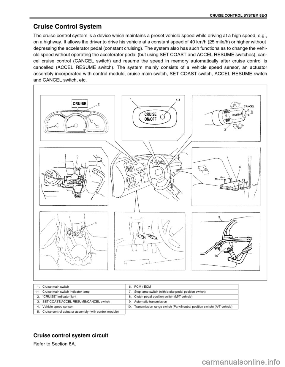
Cruise Control System
The cruise control system is a device which maintains a preset vehicle speed while driving at a high speed, e.g.,
on a highway. It allows the driver to drive his vehicle at a constant speed of 40 km/h (25 mile/h) or higher without
depressing the accelerator pedal (constant cruising). The system also has such functions as to change the vehi-
cle speed without operating the accelerator pedal (but using SET COAST and ACCEL RESUME switches), can-
cel cruise control (CANCEL switch) and resume the speed in memory automatically after cruise control is
cancelled (ACCEL RESUME switch). The system mainly consists of a vehicle speed sensor, an actuator
assembly incorporated with control module, cruise main switch, SET COAST switch, ACCEL RESUME switch
and CANCEL switch, etc.
Cruise control system circuit
Refer to Section 8A.
1. Cruise main switch 6. PCM / ECM
1-1 Cruise main switch indicator lamp 7. Stop lamp switch (with brake pedal position switch)
2.“CRUISE” Indicator light 8. Clutch pedal position switch (M/T vehicle)
3. SET COAST/ACCEL RESUME/CANCEL switch 9. Automatic transmission
4. Vehicle speed sensor 10. Transmission range switch (Park/Neutral position switch) (A/T vehicle)
5. Cruise control actuator assembly (with control module)
Page 525 of 656
8E-4 CRUISE CONTROL SYSTEM
Components and functions
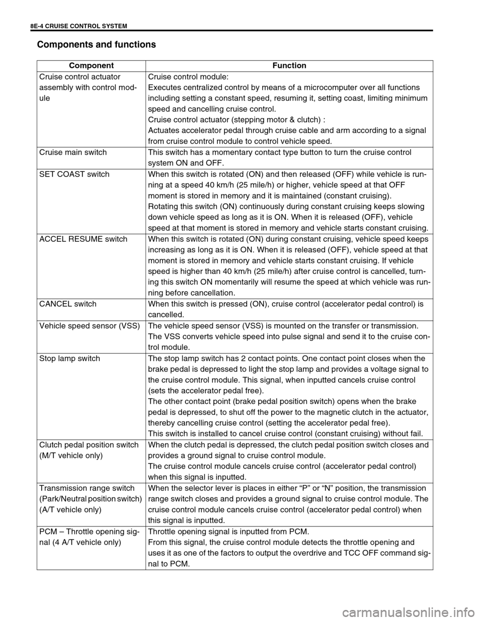
Component Function
Cruise control actuator
assembly with control mod-
uleCruise control module:
Executes centralized control by means of a microcomputer over all functions
including setting a constant speed, resuming it, setting coast, limiting minimum
speed and cancelling cruise control.
Cruise control actuator (stepping motor & clutch) :
Actuates accelerator pedal through cruise cable and arm according to a signal
from cruise control module to control vehicle speed.
Cruise main switch This switch has a momentary contact type button to turn the cruise control
system ON and OFF.
SET COAST switch When this switch is rotated (ON) and then released (OFF) while vehicle is run-
ning at a speed 40 km/h (25 mile/h) or higher, vehicle speed at that OFF
moment is stored in memory and it is maintained (constant cruising).
Rotating this switch (ON) continuously during constant cruising keeps slowing
down vehicle speed as long as it is ON. When it is released (OFF), vehicle
speed at that moment is stored in memory and vehicle starts constant cruising.
ACCEL RESUME switch When this switch is rotated (ON) during constant cruising, vehicle speed keeps
increasing as long as it is ON. When it is released (OFF), vehicle speed at that
moment is stored in memory and vehicle starts constant cruising. If vehicle
speed is higher than 40 km/h (25 mile/h) after cruise control is cancelled, turn-
ing this switch ON momentarily will resume the speed at which vehicle was run-
ning before cancellation.
CANCEL switch When this switch is pressed (ON), cruise control (accelerator pedal control) is
cancelled.
Vehicle speed sensor (VSS) The vehicle speed sensor (VSS) is mounted on the transfer or transmission.
The VSS converts vehicle speed into pulse signal and send it to the cruise con-
trol module.
Stop lamp switch The stop lamp switch has 2 contact points. One contact point closes when the
brake pedal is depressed to light the stop lamp and provides a voltage signal to
the cruise control module. This signal, when inputted cancels cruise control
(sets the accelerator pedal free).
The other contact point (brake pedal position switch) opens when the brake
pedal is depressed, to shut off the power to the magnetic clutch in the actuator,
thereby cancelling cruise control (setting the accelerator pedal free).
This switch is installed to cancel cruise control (constant cruising) without fail.
Clutch pedal position switch
(M/T vehicle only)When the clutch pedal is depressed, the clutch pedal position switch closes and
provides a ground signal to cruise control module.
The cruise control module cancels cruise control (accelerator pedal control)
when this signal is inputted.
Transmission range switch
(Park/Neutral position switch)
(A/T vehicle only)When the selector lever is places in either “P” or “N” position, the transmission
range switch closes and provides a ground signal to cruise control module. The
cruise control module cancels cruise control (accelerator pedal control) when
this signal is inputted.
PCM – Throttle opening sig-
nal (4 A/T vehicle only)Throttle opening signal is inputted from PCM.
From this signal, the cruise control module detects the throttle opening and
uses it as one of the factors to output the overdrive and TCC OFF command sig-
nal to PCM.