oil temperature SUZUKI GRAND VITARA 2001 2.G User Guide
[x] Cancel search | Manufacturer: SUZUKI, Model Year: 2001, Model line: GRAND VITARA, Model: SUZUKI GRAND VITARA 2001 2.GPages: 656, PDF Size: 14.31 MB
Page 56 of 656
AIR CONDITIONING (OPTIONAL) 1B-31
INSPECTION
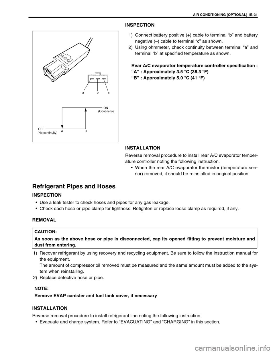
1) Connect battery positive (+) cable to terminal “b” and battery
negative (–) cable to terminal “c” as shown.
2) Using ohmmeter, check continuity between terminal “a” and
terminal “b” at specified temperature as shown.
Rear A/C evaporator temperature controller specification :
“A” : Approximately 3.5 °C (38.3 °F)
“B” : Approximately 5.0 °C (41 °F)
INSTALLATION
Reverse removal procedure to install rear A/C evaporator temper-
ature controller noting the following instruction.
When the rear A/C evaporator thermistor (temperature sen-
sor) removed, it should be reinstalled in original position.
Refrigerant Pipes and Hoses
INSPECTION
Use a leak tester to check hoses and pipes for any gas leakage.
Check each hose or pipe clamp for tightness. Retighten or replace loose clamp as required, if any.
REMOVAL
1) Recover refrigerant by using recovery and recycling equipment. Be sure to follow the instruction manual for
the equipment.
The amount of compressor oil removed must be measured and the same amount must be added to the sys-
tem when reinstalling.
2) Replace defective hose or pipe.
INSTALLATION
Reverse removal procedure to install refrigerant line noting the following instruction.
Evacuate and charge system. Refer to “EVACUATING” and “CHARGING” in this section.
CAUTION:
As soon as the above hose or pipe is disconnected, cap its opened fitting to prevent moisture and
dust from entering.
NOTE:
Remove EVAP canister and fuel tank cover, if necessary
Page 74 of 656

POWER STEERING (P/S) SYSTEM 3B1-3
Hydraulic Pressure in P/S Circuit
Hydraulic pressure check
1) After cleaning joint of high pressure hose and P/S pump
thoroughly, disconnect hose from pump and install special
tool (oil pressure gauge, attachment and hose).
Special tool
(A) : 09915-77410
(B) : 09915-77420
2) Check each connection for fluid leakage and bleed air.
Refer to “AIR BLEEDING PROCEDURE” in this section.
3) With engine idling, turn steering wheel and warm up engine
till temperature of fluid in P/S fluid reservoir rises to 50 –
60°C (122 – 140°F).
4) Check back pressure by measuring hydraulic pressure with
engine idling and hands off steering wheel.
When back pressure is higher than specified values, check
control valve and piping for clogging.
Back pressure :
Lower than 1000 kPa (10 kg/cm
2, 142 psi) CAUTION:
Take care not to cause damage to A/C condenser during
service operation, if equipped.
1. P/S fluid reservoir
2. Attachment
3. Gasket
4. Union bolt
5. High pressure side
6. Low pressure side
1. P/S fluid reservoir 4. P/S gear box
2. Gauge valve (open) 5. High pressure side
3. P/S pump 6. Low pressure side
Page 314 of 656
ENGINE MECHANICAL (H27 ENGINE) 6A2-27
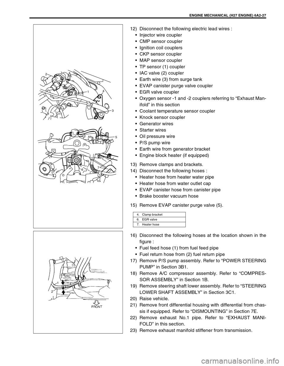
12) Disconnect the following electric lead wires :
•Injector wire coupler
•CMP sensor coupler
•Ignition coil couplers
•CKP sensor coupler
•MAP sensor coupler
•TP sensor (1) coupler
•IAC valve (2) coupler
•Earth wire (3) from surge tank
•EVAP canister purge valve coupler
•EGR valve coupler
•Oxygen sensor -1 and -2 couplers referring to “Exhaust Man-
ifold” in this section
•Coolant temperature sensor coupler
•Knock sensor coupler
•Generator wires
•Starter wires
•Oil pressure wire
•P/S pump wire
•Earth wire from generator bracket
•Engine block heater (if equipped)
13) Remove clamps and brackets.
14) Disconnect the following hoses :
•Heater hose from heater water pipe
•Heater hose from water outlet cap
•EVAP canister hose from canister pipe
•Brake booster vacuum hose
15) Remove EVAP canister purge valve (5).
16) Disconnect the following hoses at the location shown in the
figure :
•Fuel feed hose (1) from fuel feed pipe
•Fuel return hose from (2) fuel return pipe
17) Remove P/S pump assembly. Refer to “POWER STEERING
PUMP” in Section 3B1.
18) Remove A/C compressor assembly. Refer to “COMPRES-
SOR ASSEMBLY” in Section 1B.
19) Remove steering shaft lower assembly. Refer to “STEERING
LOWER SHAFT ASSEMBLY” in Section 3C1.
20) Raise vehicle.
21) Remove front differential housing with differential from chas-
sis if equipped. Refer to “DISMOUNTING” in Section 7E.
22) Remove exhaust No.1 pipe. Refer to “EXHAUST MANI-
FOLD” in this section.
23) Remove exhaust manifold stiffener from transmission.
4. Clamp bracket
6. EGR valve
7. Heater hose
2
14
3
75
6
Page 338 of 656
ENGINE AND EMISSION CONTROL SYSTEM (SEQUENTIAL MULTIPORT FUEL INJECTION FOR H27 ENGINE) 6E2-5
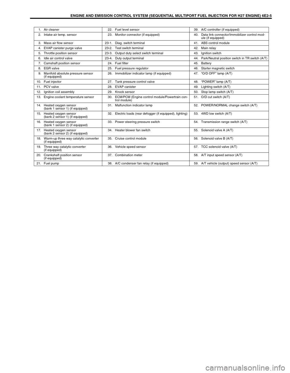
1. Air cleaner 22. Fuel level sensor 39. A/C controller (if equipped)
2. Intake air temp. sensor 23. Monitor connector (if equipped) 40. Data link connector/Immobilizer control mod-
ule (if equipped)
3. Mass air flow sensor 23-1. Diag. switch terminal 41. ABS control module
4. EVAP canister purge valve 23-2. Test switch terminal 42. Main relay
5. Throttle position sensor 23-3. Output duty select switch terminal 43. Ignition switch
6. Idle air control valve 23-4. Duty output terminal 44. Park/Neutral position switch in TR switch (A/T)
7. Camshaft position sensor 24. Fuel filter 45. Battery
8. EGR valve 25. Fuel pressure regulator 46. Starter magnetic switch
9. Manifold absolute pressure sensor
(if equipped)26. Immobilizer indicator lamp (if equipped) 47.“O/D OFF” lamp (A/T)
10. Fuel injector 27. Tank pressure control valve 48.“POWER” lamp (A/T)
11. PCV valve 28. EVAP canister 49. Lighting switch (A/T)
12. Ignition coil assembly 29. Knock sensor 50. Stop lamp switch (A/T)
13. Engine coolant temperature sensor 30. ECM/PCM (Engine control module/Powertrain con-
trol module)51. O/D cut switch (A/T)
14. Heated oxygen sensor
(bank 1 sensor 1) (if equipped)31. Malfunction indicator lamp 52. POWER/NORMAL change switch (A/T)
15. Heated oxygen sensor
(bank 2 sensor 1) (if equipped)32. Electric loads (rear defogger (if equipped), lighting) 53. 4WD low switch (A/T)
16. Heated oxygen sensor
(bank 1 sensor 2) (if equipped)33. Power steering pressure switch 54. Transmission range switch (A/T)
17. Heated oxygen sensor
(bank 2 sensor 2) (if equipped)34. Heater blower fan switch 55. Solenoid valve A (A/T)
18. Warm-up three way catalytic converter
(if equipped)35. Cruise control module 56. Solenoid valve B (A/T)
19. Three way catalytic converter
(if equipped)36. Vehicle speed sensor 57. TCC solenoid valve (A/T)
20. Crankshaft position sensor
(if equipped)37. Combination meter 58. A/T input speed sensor (A/T)
21. Fuel pump 38. A/C condenser fan relay (if equipped) 59. A/T vehicle (output) speed sensor (A/T)
Page 448 of 656
AUTOMATIC TRANSMISSION (4 A/T) 7B1-39
Line Pressure Test
Purpose of this test is to check operating conditions of each part
by measuring fluid pressure in fluid pressure line. Line pressure
test requires following conditions.
•Automatic fluid is at normal operating temperature (70 to 80
°
C/158 – 176 °F).
•Fluid is filled to proper level (between FULL HOT and LOW
HOT on dipstick).
1) Apply parking brake securely and place checks against
wheels.
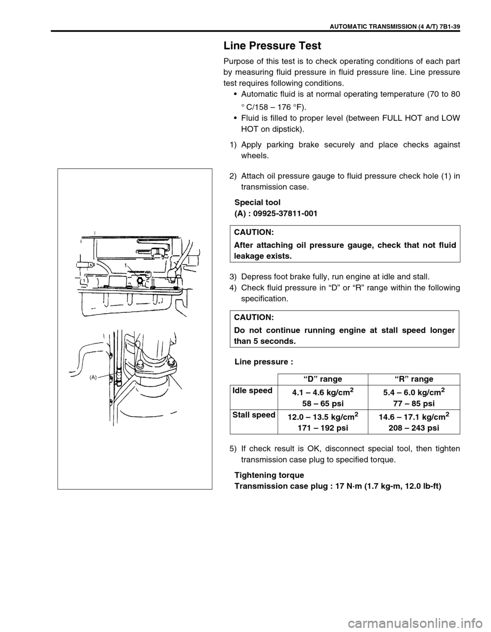
2) Attach oil pressure gauge to fluid pressure check hole (1) in
transmission case.
Special tool
(A) : 09925-37811-001
3) Depress foot brake fully, run engine at idle and stall.
4) Check fluid pressure in “D” or “R” range within the following
specification.
Line pressure :
5) If check result is OK, disconnect special tool, then tighten
transmission case plug to specified torque.
Tightening torque
Transmission case plug : 17 N·m (1.7 kg-m, 12.0 lb-ft) CAUTION:
After attaching oil pressure gauge, check that not fluid
leakage exists.
CAUTION:
Do not continue running engine at stall speed longer
than 5 seconds.
“D” range“R” range
Idle speed
4.1 – 4.6 kg/cm
2
58 – 65 psi5.4 – 6.0 kg/cm
2
77 – 85 psi
Stall speed
12.0 – 13.5 kg/cm
2
171 – 192 psi14.6 – 17.1 kg/cm
2
208 – 243 psi
Page 453 of 656

7B1-44 AUTOMATIC TRANSMISSION (4 A/T)
LEVEL CHECK AT ROOM TEMPERATURE
The fluid level check at room temperature (20 – 30 °C (68 – 86
°F)) performed after repair or fluid change before test driving is
just preparation for level check of normal operating temperature.
The checking procedure itself is the same as that described previ-
ously. If the fluid level is between FULL COLD and LOW COLD,
proceed to test drive. And when the fluid temperature has
reached the normal operating temperature, check fluid level again
and adjust it as necessary.
Fluid change
1) Lift up vehicle.
2) With engine is cool, remove drain plug (1) from oil pan and
drain A/T fluid.
3) Install drain plug (1).
Tightening torque
A/T fluid drain plug (a) :
23 N·m (2.3 kg-m, 17.0 lb-ft)
4) Lower vehicle and fill proper amount of an equivalent of
DEXRON
®-III.
5) Check fluid level referring to “LEVEL CHECK NORMAL
OPERATING TEMPERATURE” of “FLUID LEVEL” in this
section.
Fluid specification :
An equivalent of DEXRON
®-III
Fluid capacity
When draining from drain plug hole:
2.5 liters (5.28/4.40 US/lmp.pt.)
When overhauling:
6.8 liters (14.37/11.97 US/lmp.pt.)
Page 512 of 656
INSTRUMENTATION/DRIVER INFORMATION 8C-1
8C
SECTION 8C
INSTRUMENTATION/DRIVER INFORMATION
CONTENTS
General Description ........................................8C-2
Combination Meter ........................................8C-2
On-vehicle Service ..........................................8C-4
Fuel Meter/Fuel Gauge Unit ..........................8C-4
Fuel level sensor (sender gauge) ..............8C-4
Engine Coolant Temperature (ECT) Meter
and Sensor ....................................................8C-5Engine coolant temperature sensor .......... 8C-5
Oil Pressure Light ......................................... 8C-5
Oil pressure switch .................................... 8C-5
Brake Warning Light ..................................... 8C-5
Brake fluid level switch .............................. 8C-5
WARNING:
For vehicles equipped with Supplemental Restraint (Air Bag) System:
Service on and around the air bag system components or wiring must be performed only by an
authorized SUZUKI dealer. Refer to “Air Bag System Components and Wiring Location View” under
“General Description” in air bag system section in order to confirm whether you are performing ser-
vice on or near the air bag system components or wiring. Please observe all WARNINGS and “Ser-
vice Precautions” under “On-Vehicle Service” in air bag system section before performing service
on or around the air bag system components or wiring. Failure to follow WARNINGS could result in
unintentional activation of the system or could render the system inoperative. Either of these two
conditions may result in severe injury.
Technical service work must be started at least 90 seconds after the ignition switch is turned to the
“LOCK” position and the negative cable is disconnected from the battery. Otherwise, the system
may be activated by reserve energy in the Sensing and Diagnostic Module (SDM).
NOTE:
For the descriptions (items) not found in this section, refer to the same section of the Service Manual
mentioned in the FOREWORD of this manual.
Page 513 of 656
8C-2 INSTRUMENTATION/DRIVER INFORMATION
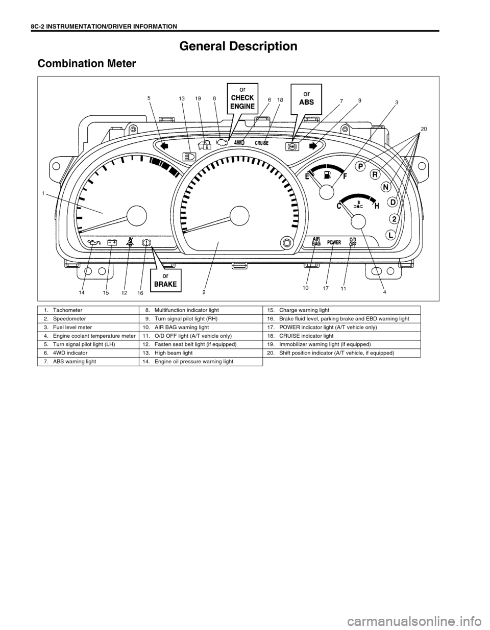
General Description
Combination Meter
1. Tachometer 8. Multifunction indicator light 15. Charge warning light
2. Speedometer 9. Turn signal pilot light (RH) 16. Brake fluid level, parking brake and EBD warning light
3. Fuel level meter 10. AIR BAG warning light 17. POWER indicator light (A/T vehicle only)
4. Engine coolant temperature meter 11. O/D OFF light (A/T vehicle only) 18. CRUISE indicator light
5. Turn signal pilot light (LH) 12. Fasten seat belt light (if equipped) 19. Immobilizer warning light (if equipped)
6. 4WD indicator 13. High beam light 20. Shift position indicator (A/T vehicle, if equipped)
7. ABS warning light 14. Engine oil pressure warning light
Page 516 of 656
INSTRUMENTATION/DRIVER INFORMATION 8C-5
Engine Coolant Temperature (ECT) Meter and
Sensor
Engine coolant temperature sensor
REMOVAL AND INSTALLATION
Refer to “ECT SENSOR” in Section 6E2.
Oil Pressure Light
Oil pressure switch
REMOVAL AND INSTALLATION
Refer to “OIL PRESSURE CHECK” in Section 6A2.
Brake Warning Light
Brake fluid level switch
INSPECTION
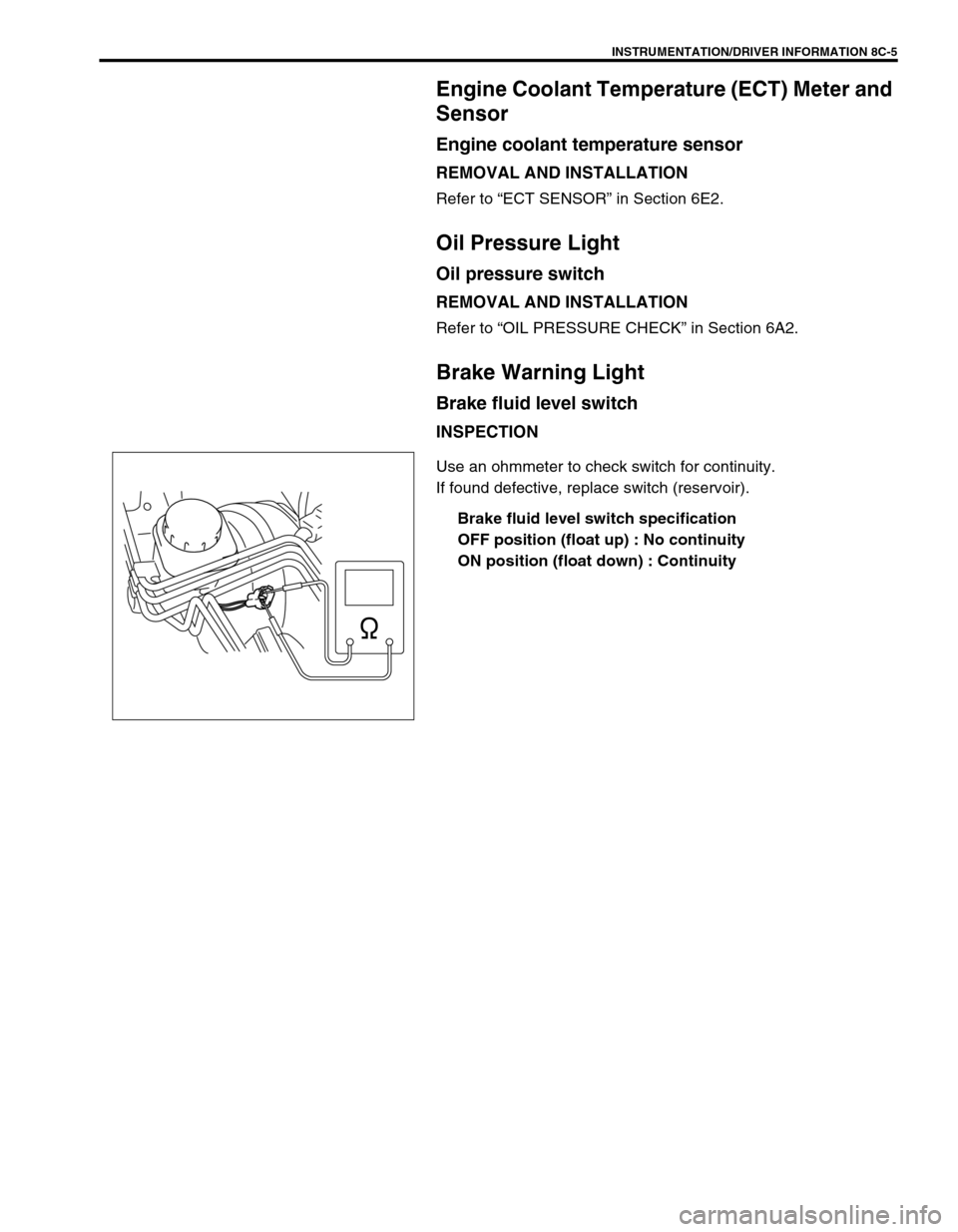
Use an ohmmeter to check switch for continuity.
If found defective, replace switch (reservoir).
Brake fluid level switch specification
OFF position (float up) : No continuity
ON position (float down) : Continuity
Page 629 of 656

10B-52 AIR BAG SYSTEM
LIVE (UNDEPLOYED) AIR BAG (INFLATOR) MODULES
Special care is necessary when handling and storing a live (unde-
ployed) air bag (inflator) modules.
The rapid gas generation produced during deployment of the air
bag could cause the air bag (inflator) module, or an object in front
of the air bag (inflator) module, to be thrown through the air in the
unlikely event of an accidental deployment.
•Never attempt disassembly of the air bag (inflator) modules.
•If any abnormality is found, be sure to replace it with new
one as an assembly.
•When an abnormality is noted as existing in the live (unde-
ployed) air bag (inflator) module, be sure to deploy it before
discarding it.
•When grease, cleaning agent, oil, water, etc., got on the air
bag (inflator) modules (driver and passenger), wipe it off
immediately with a dry cloth.
•If air bag (inflator) module was dropped from a height of 90
cm (3 ft) or more, it should be replaced with a new one as an
assembly. WARNING:
Never attempt to measure the resistance of the air bag
(inflator) modules (driver and passenger). It is very dan-
gerous as the electric current from the tester may deploy
the air bag.
WARNING:
For handling and storage of a live air bag (inflator)
module, select a place where the ambient temperature
below 65°
°° °C (150°
°° °F), without high humidity and away
from electric noise.
When carrying a live air bag (inflator) module, make
sure the bag opening is pointed away from you. In
case of an accidental deployment, the bag will then
deploy with minimal chance of injury. Never carry the
air bag (inflator) module by the wires or connector on
the underside of the module.
Otherwise, personal injury may result.