belt SUZUKI GRAND VITARA 2001 2.G Owner's Manual
[x] Cancel search | Manufacturer: SUZUKI, Model Year: 2001, Model line: GRAND VITARA, Model: SUZUKI GRAND VITARA 2001 2.GPages: 656, PDF Size: 14.31 MB
Page 328 of 656
ENGINE FUEL 6C-1
6C
SECTION 6C
ENGINE FUEL
CONTENTS
General Description ....................................... 6C-1
Fuel System ................................................. 6C-1On-Vehicle Service ........................................ 6C-2
Fuel Tank ..................................................... 6C-2
Fuel Lines .................................................... 6C-5
General Description
Fuel System
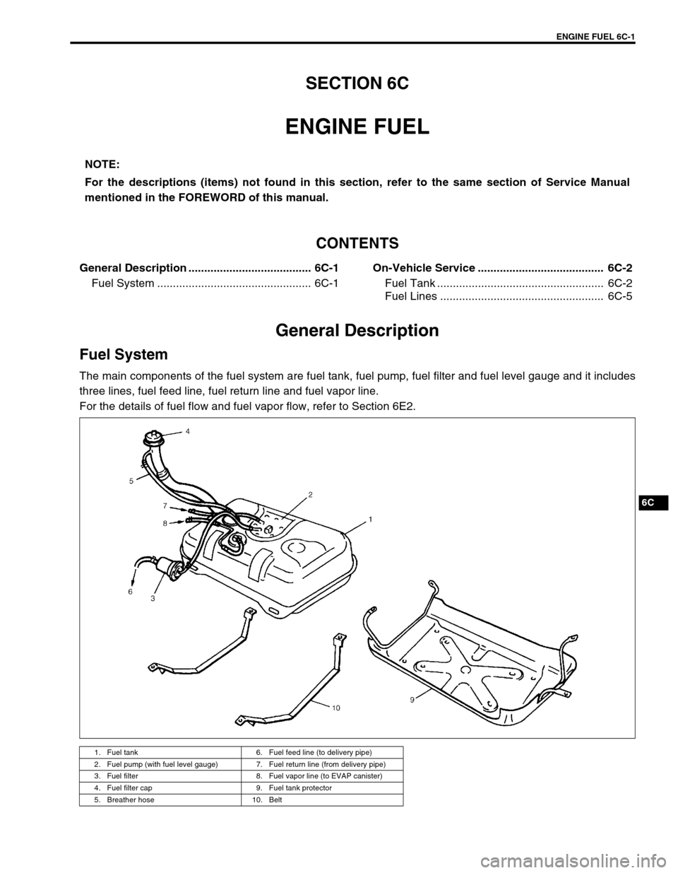
The main components of the fuel system are fuel tank, fuel pump, fuel filter and fuel level gauge and it includes
three lines, fuel feed line, fuel return line and fuel vapor line.
For the details of fuel flow and fuel vapor flow, refer to Section 6E2.NOTE:
For the descriptions (items) not found in this section, refer to the same section of Service Manual
mentioned in the FOREWORD of this manual.
1. Fuel tank 6. Fuel feed line (to delivery pipe)
2. Fuel pump (with fuel level gauge) 7. Fuel return line (from delivery pipe)
3. Fuel filter 8. Fuel vapor line (to EVAP canister)
4. Fuel filter cap 9. Fuel tank protector
5. Breather hose 10. Belt
Page 331 of 656

6C-4 ENGINE FUEL
INSTALLATION
1) Install fuel pump assembly, fuel cut valve and vapor control
valve to fuel tank. Refer to “FUEL PUMP” in this section.
2) Connect fuel hoses to fuel tank, fuel cut valve, and vapor
control valve, check valve and fuel pump assembly.
After connecting, clamp hoses securely.
3) Install inlet valve to fuel tank. If deformed or damaged in any
other way, replace with a new one.
4) Install fuel tank by using fuel tank belts and then install pro-
tector to vehicle.
Tightening torque
Fuel tank bolt (a) : 50 N·m (5.0 kg-m, 36.5 lb-ft)
Fuel tank protector bolt (a) : 50 N·m (5.0 kg-m, 36.5 lb-ft)
5) Connect fuel filler hose to fuel filler neck with match the
match marks. And then clamp the securely.
6) Connect fuel filler hose to fuel tank and breather hose to fuel
filler neck. Clamp them securely.
Tightening torque
Breather hose clamp (b) : 2.0 N·m (0.2 kg-m, 2.0 lb-ft)
Fuel filler hose clamp (c) : 4.0 N·m (0.4 kg-m, 3.0 lb-ft)
7) Install fuel filler hose protector.
8) Connect fuel vapor hose (1) and return hose (2) to fuel pipe
and clamp them securely.
9) Connect fuel filter inlet hose to fuel filter.
10) Connect coupler to fuel pump assembly.
11) Connect negative (–) cable to battery.
12) Upon completion of installation, check fuel system for leak-
age.
1. Fuel tank 9. Fuel tank protector
2. Fuel pump (with fuel level gauge) 10. Belt
3. Fuel filter 11. Filler neck
4. Fuel filler cap 12. Breather pipe
5. Breather hose 13. Filler hose
6. Fuel feed line (to delivery pipe) 14. Tank inlet valve
7. Fuel return line (from delivery pipe) 15. Fuel cut valve
8. Fuel vapor line (to EVAP canister)
1. Fuel filter
2. Fuel filter outlet hose
3. Fuel filter inlet hose
Page 513 of 656
8C-2 INSTRUMENTATION/DRIVER INFORMATION
General Description
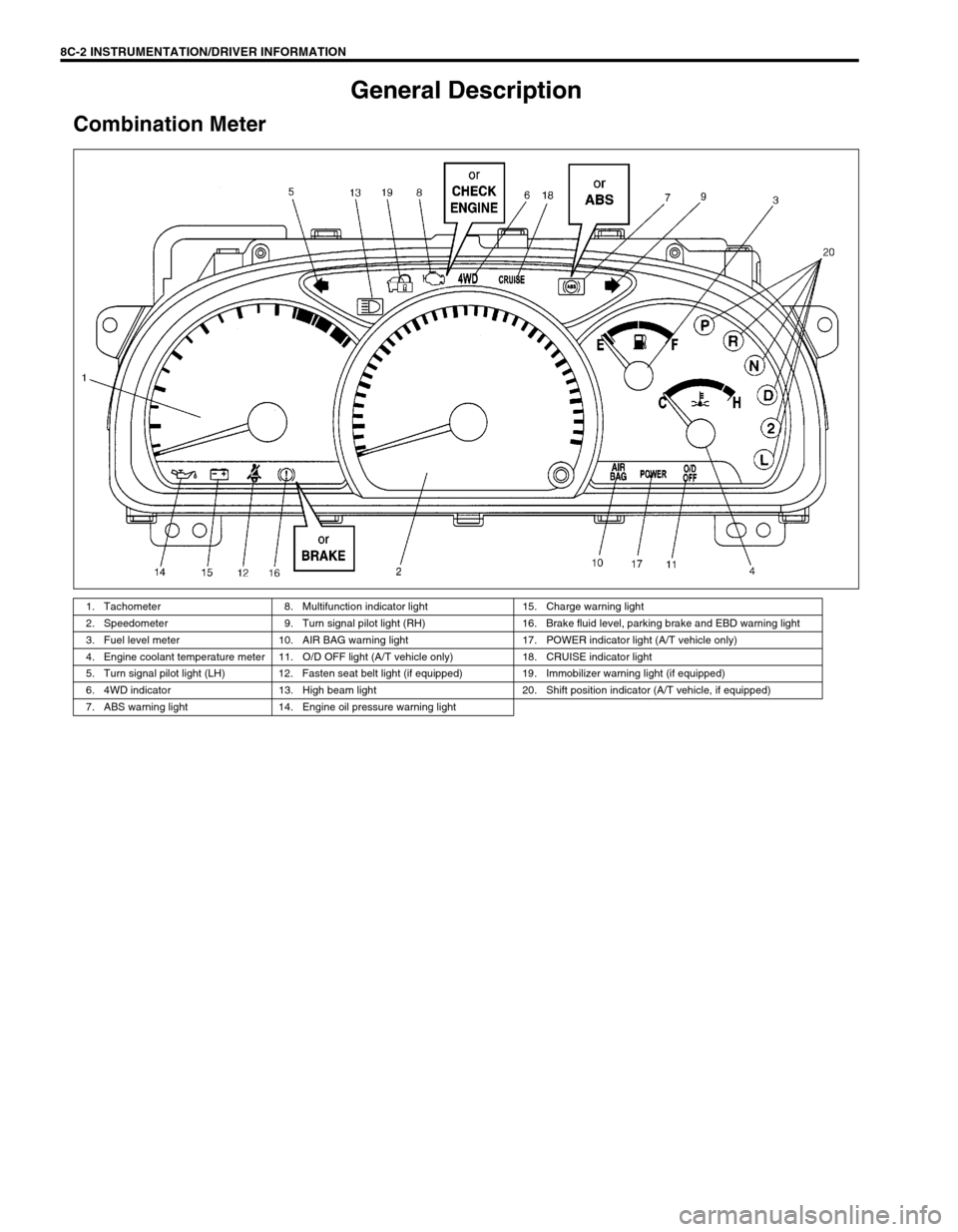
Combination Meter
1. Tachometer 8. Multifunction indicator light 15. Charge warning light
2. Speedometer 9. Turn signal pilot light (RH) 16. Brake fluid level, parking brake and EBD warning light
3. Fuel level meter 10. AIR BAG warning light 17. POWER indicator light (A/T vehicle only)
4. Engine coolant temperature meter 11. O/D OFF light (A/T vehicle only) 18. CRUISE indicator light
5. Turn signal pilot light (LH) 12. Fasten seat belt light (if equipped) 19. Immobilizer warning light (if equipped)
6. 4WD indicator 13. High beam light 20. Shift position indicator (A/T vehicle, if equipped)
7. ABS warning light 14. Engine oil pressure warning light
Page 514 of 656

INSTRUMENTATION/DRIVER INFORMATION 8C-3
COMBINATION METER INTERNAL CIRCUITS
COMBINATION METER COUPLERS
[A] : Coupler A [B] : Coupler B [C] : Coupler C
1. To Cruise control module (if equipped) GRY/YEL 1. To door switch (drive side) BLK/BLU 1. To ground BLK
2. Blank–2. To transmission range switch
(A/T vehicle only, if equipped) LGRN/BLU 2. To ECM (PCM for A/T vehicle) BRN
3. To ignition switch BLK/WHT 3. To transmission range switch
(A/T vehicle only, if equipped) 2GRN/ORN 3. To ignition switch PPL/RED
4. Blank–4. To transmission range switch
(A/T vehicle only, if equipped) DYEL/GRN 4. To brake fluid level switch RED/BLK
5. To ABS control module (if equipped) BLU/ORN 5. To transmission range switch
(A/T vehicle only, if equipped) NORN/BLU 5. To parking brake switch PPL
6. To PCM (A/T vehicle only) GRY/BLU 6. To transmission range switch
(A/T vehicle only, if equipped) PORN/GRN 6. To seat belt switch GRY/RED
7. To ABS control module (if equipped) BRN 7. To transmission range switch
(A/T vehicle only, if equipped) RRED 7. To generator WHT/RED
8. To VSS BLU/YEL 8. To illumination control module RED/GRN 8. To engine oil pressure switch YEL/BLK
9. To combination switch GRN/RED 9. To PCM (A/T vehicle only) WHT/BLK 9. To combination switch RED/YEL
10. To air bag SDM BLU 10. To ECT sensor YEL/WHT 10. To ignition switch BLU/RED
11. To main fuse WHT/BLU 11. To fuel level gauge BLU/WHT
12. To fuse box WHT 12. To ground BLU/YEL
13. To combination switch RED 13. To combination switch GRN/YEL
14. To immobilizer control module
(if equipped)PPL
15. To ECM (PCM for A/T vehicle) PPL/YEL
16. To ECM (PCM for A/T vehicle) ORN/BLK
P R N D 2 LCRUISEPOWER4WDSPEED
METERTACHO
METERFUEL
METERTEMP.
METER
A-11
A-13 A-8 B-12 B-11 C-8 A-15 A-6 A-1 B-9 A-16 A-14 C-7 C-1 A-10 C-3 C-4 C-5 A-7 A-5 B-8 B-1B-10 C-2 A-12 A-3B-13 B-2 B-3 B-4 B-5 B- B-6 C-9 C-10 A-9ABS circuit EBD circuit Air bag circuit
or ABS or BRAKE
if equipped
or CHECK
ENGINE
NOTE:
Terminal arrangement of coupler viewed from harness side.
Page 551 of 656
9-6 BODY SERVICE
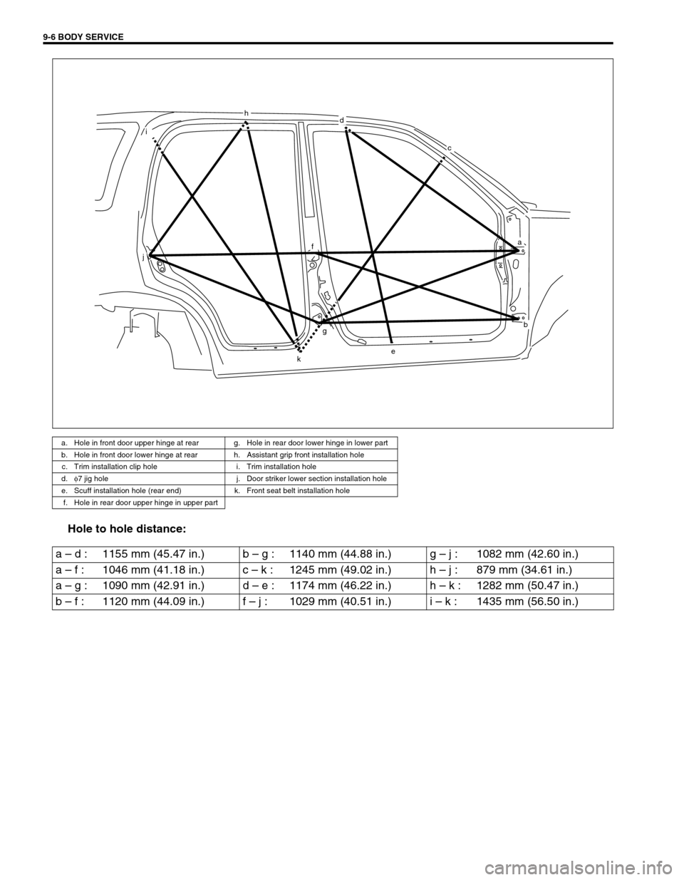
Hole to hole distance:
a. Hole in front door upper hinge at rear g. Hole in rear door lower hinge in lower part
b. Hole in front door lower hinge at rear h. Assistant grip front installation hole
c. Trim installation clip hole i. Trim installation hole
d.φ
7 jig hole j. Door striker lower section installation hole
e. Scuff installation hole (rear end) k. Front seat belt installation hole
f. Hole in rear door upper hinge in upper part
hd
c
f
i
j
ke
gb
a
a – d : 1155 mm (45.47 in.) b – g : 1140 mm (44.88 in.) g – j : 1082 mm (42.60 in.)
a – f : 1046 mm (41.18 in.) c – k : 1245 mm (49.02 in.) h – j : 879 mm (34.61 in.)
a – g : 1090 mm (42.91 in.) d – e : 1174 mm (46.22 in.) h – k : 1282 mm (50.47 in.)
b – f : 1120 mm (44.09 in.) f – j : 1029 mm (40.51 in.) i – k : 1435 mm (56.50 in.)
Page 553 of 656

9-8 BODY SERVICE
Seat
Second Seat
REMOVAL
1) Remove adjuster extension cover.
2) Remove adjuster extension bracket.
3) Remove front and rear adjuster inside covers.
4) Remove adjuster outside covers.
5) Remove second seat mounting bolts.
6) Disassemble and repair seat as necessary.
INSTALLATION
Reverse removal procedure to install rear seat, noting the following instruction.
•Tighten second seat mounting bolts as specified torque.
1. Head restraint 6. Rod 11. Seat adjuster cover 16. Rod belt (if equipped)
2. Head restraint guide 7. Seat reclining assembly cover 12. Cover Tightening torque
3. Seat back 8. Seat cushion 13. Adjuster extension bracket
4. Tether anchor hook 9. Adjuster handle (back side) 14. Adjuster handle (front side)
5. Seat reclining assembly 10. Seat adjuster 15. Second seat mounting bolt
Page 564 of 656
BODY SERVICE 9-19
Exterior and Interior Trim
Floor Carpet
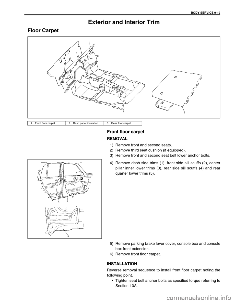
Front floor carpet
REMOVAL
1) Remove front and second seats.
2) Remove third seat cushion (if equipped).
3) Remove front and second seat belt lower anchor bolts.
4) Remove dash side trims (1), front side sill scuffs (2), center
pillar inner lower trims (3), rear side sill scuffs (4) and rear
quarter lower trims (5).
5) Remove parking brake lever cover, console box and console
box front extension.
6) Remove front floor carpet.
INSTALLATION
Reverse removal sequence to install front floor carpet noting the
following point.
•Tighten seat belt anchor bolts as specified torque referring to
Section 10A.
1. Front floor carpet 2. Dash panel insulation 3. Rear floor carpet
3
Page 566 of 656
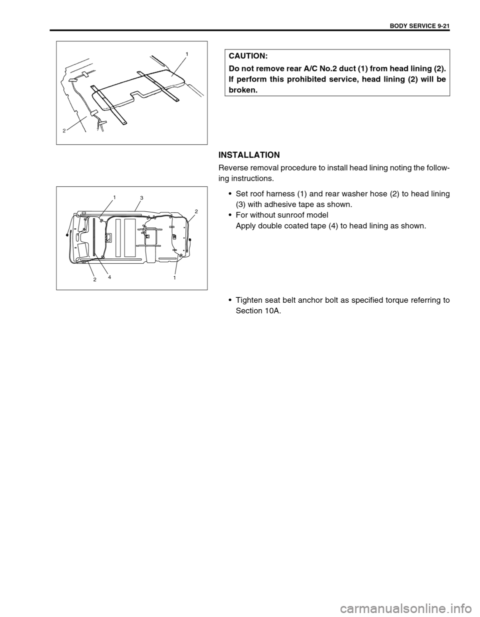
BODY SERVICE 9-21
INSTALLATION
Reverse removal procedure to install head lining noting the follow-
ing instructions.
•Set roof harness (1) and rear washer hose (2) to head lining
(3) with adhesive tape as shown.
•For without sunroof model
Apply double coated tape (4) to head lining as shown.
•Tighten seat belt anchor bolt as specified torque referring to
Section 10A. CAUTION:
Do not remove rear A/C No.2 duct (1) from head lining (2).
If perform this prohibited service, head lining (2) will be
broken.
13
2
1 4
2
Page 568 of 656

RESTRAINT SYSTEM 10-1
10
SECTION 10
RESTRAINT SYSTEM
Seat Belt ......................................................................................................................................... Section 10A
Air Bag System.............................................................................................................................. Section 10B
CONTENTS
General Description ....................................... 10-2
WARNING:
For vehicles equipped with Supplemental Restraint (Air Bag) System:
Service on and around the air bag system components or wiring must be performed only by an
authorized SUZUKI dealer. Refer to “Air Bag System Components and Wiring Location View” under
“General Description” in air bag system section in order to confirm whether you are performing ser-
vice on or near the air bag system components or wiring. Please observe all WARNINGS and “Ser-
vice Precautions” under “On-Vehicle Service” in air bag system section before performing service
on or around the air bag system components or wiring. Failure to follow WARNINGS could result in
unintentional activation of the system or could render the system inoperative. Either of these two
conditions may result in severe injury.
Technical service work must be started at least 90 seconds after the ignition switch is turned to the
“LOCK” position and the negative cable is disconnected from the battery. Otherwise, the system
may be activated by reserve energy in the Sensing and Diagnostic Module (SDM).
Page 569 of 656
10-2 RESTRAINT SYSTEM
General Description
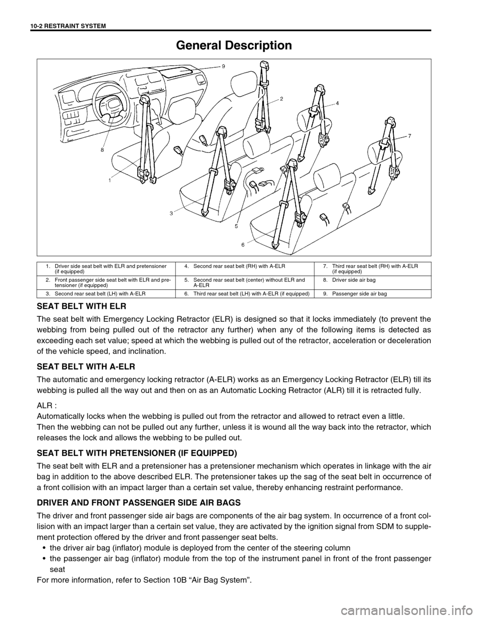
SEAT BELT WITH ELR
The seat belt with Emergency Locking Retractor (ELR) is designed so that it locks immediately (to prevent the
webbing from being pulled out of the retractor any further) when any of the following items is detected as
exceeding each set value; speed at which the webbing is pulled out of the retractor, acceleration or deceleration
of the vehicle speed, and inclination.
SEAT BELT WITH A-ELR
The automatic and emergency locking retractor (A-ELR) works as an Emergency Locking Retractor (ELR) till its
webbing is pulled all the way out and then on as an Automatic Locking Retractor (ALR) till it is retracted fully.
ALR :
Automatically locks when the webbing is pulled out from the retractor and allowed to retract even a little.
Then the webbing can not be pulled out any further, unless it is wound all the way back into the retractor, which
releases the lock and allows the webbing to be pulled out.
SEAT BELT WITH PRETENSIONER (IF EQUIPPED)
The seat belt with ELR and a pretensioner has a pretensioner mechanism which operates in linkage with the air
bag in addition to the above described ELR. The pretensioner takes up the sag of the seat belt in occurrence of
a front collision with an impact larger than a certain set value, thereby enhancing restraint performance.
DRIVER AND FRONT PASSENGER SIDE AIR BAGS
The driver and front passenger side air bags are components of the air bag system. In occurrence of a front col-
lision with an impact larger than a certain set value, they are activated by the ignition signal from SDM to supple-
ment protection offered by the driver and front passenger seat belts.
•the driver air bag (inflator) module is deployed from the center of the steering column
•the passenger air bag (inflator) module from the top of the instrument panel in front of the front passenger
seat
For more information, refer to Section 10B “Air Bag System”.
1. Driver side seat belt with ELR and pretensioner
(if equipped) 4. Second rear seat belt (RH) with A-ELR 7. Third rear seat belt (RH) with A-ELR
(if equipped)
2. Front passenger side seat belt with ELR and pre-
tensioner (if equipped) 5. Second rear seat belt (center) without ELR and
A-ELR8. Driver side air bag
3. Second rear seat belt (LH) with A-ELR 6. Third rear seat belt (LH) with A-ELR (if equipped) 9. Passenger side air bag