idle air control SUZUKI GRAND VITARA 2001 2.G Owner's Manual
[x] Cancel search | Manufacturer: SUZUKI, Model Year: 2001, Model line: GRAND VITARA, Model: SUZUKI GRAND VITARA 2001 2.GPages: 656, PDF Size: 14.31 MB
Page 345 of 656
6E2-12 ENGINE AND EMISSION CONTROL SYSTEM (SEQUENTIAL MULTIPORT FUEL INJECTION FOR H27 ENGINE)
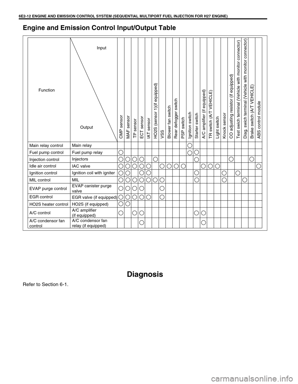
Engine and Emission Control Input/Output Table
Diagnosis
Refer to Section 6-1.
Ignition coil with igniter
HO2S heater control
Input
Output Function
Main relay control
Fuel pump control
Injection control
Ignition control
MIL control Idle air control
EVAP purge control
EGR control
A/C control
A/C condensor fan
controlMain relay
Fuel pump relay
Injectors
MIL
EVAP canister purge
valve IAC valve
EGR valve (if equipped)
HO2S (if equipped)
A/C amplifier
(if equipped)
A/C condensor fan
relay (if equipped)
CMP sensor
MAF sensor
TP sensor
ECT sensor
IAT sensor
HO2S (sensor 1)(if equipped)
VSS
Blower fan switch
Rear defogger switch
PSP switch
Ignition switch
Starter switch
A/C amplifier (if equipped)
TR switch (A/T VEHICLE)
Light switch
Knock sensor
CO adjusting resistor (if equipped)
Test swich terminal (Vehicle with monitor connector)
Diag. swich terminal (Vehicle with monitor connector)
Brake switch (A/T VEHICLE)
ABS control module
Page 348 of 656
ENGINE AND EMISSION CONTROL SYSTEM (SEQUENTIAL MULTIPORT FUEL INJECTION FOR H27 ENGINE) 6E2-15
Idle Speed/Idle Air Control (IAC) Duty Inspec-
tion
Before idle speed/IAC duty check, make sure of the following.
•Lead wires and hoses of engine/emission control systems
are connected securely.
•Accelerator cable is adjusted.
•Ignition timing is within specification.
•All accessories (wipers, heater, lights, A/C, etc.) are out of
service.
•Air cleaner has been properly installed and is in good condi-
tion.
•ECM (PCM) does not detect any malfunction DTC.
After above items are all confirmed, check idle speed and IAC
duty as follows.
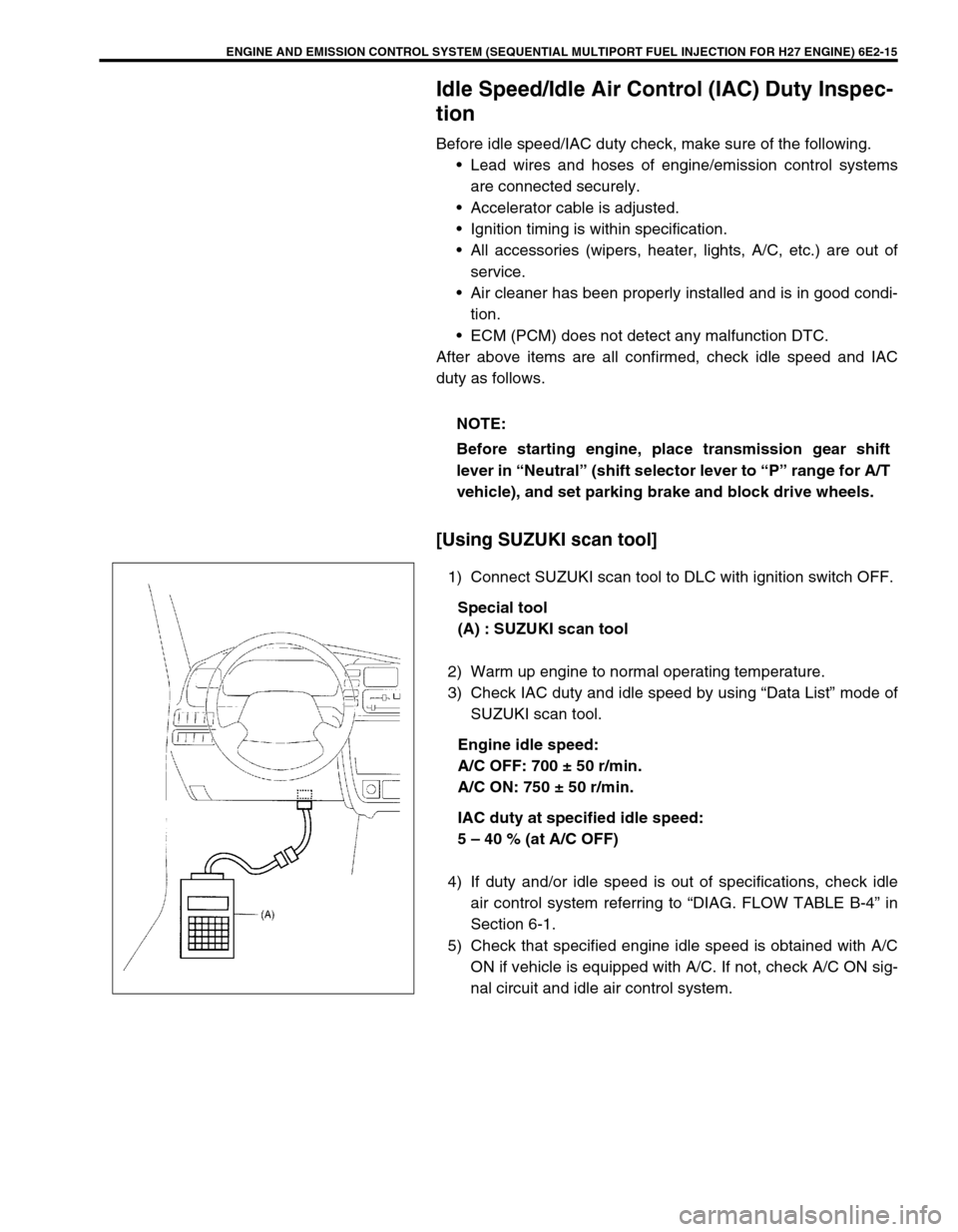
[Using SUZUKI scan tool]
1) Connect SUZUKI scan tool to DLC with ignition switch OFF.
Special tool
(A) : SUZUKI scan tool
2) Warm up engine to normal operating temperature.
3) Check IAC duty and idle speed by using “Data List” mode of
SUZUKI scan tool.
Engine idle speed:
A/C OFF: 700 ± 50 r/min.
A/C ON: 750 ± 50 r/min.
IAC duty at specified idle speed:
5 – 40 % (at A/C OFF)
4) If duty and/or idle speed is out of specifications, check idle
air control system referring to “DIAG. FLOW TABLE B-4” in
Section 6-1.
5) Check that specified engine idle speed is obtained with A/C
ON if vehicle is equipped with A/C. If not, check A/C ON sig-
nal circuit and idle air control system. NOTE:
Before starting engine, place transmission gear shift
lever in “Neutral” (shift selector lever to “P” range for A/T
vehicle), and set parking brake and block drive wheels.
Page 349 of 656

6E2-16 ENGINE AND EMISSION CONTROL SYSTEM (SEQUENTIAL MULTIPORT FUEL INJECTION FOR H27 ENGINE)
[Not using SUZUKI scan tool] (vehicle with monitor
connector)
1) Disconnect scan tool from DLC if connected.
2) Warm up engine to normal operating temperature.
3) Stop engine and connect duty meter (3) between duty output
terminal and ground terminal of monitor connector (1).
4) Using service wire (2), ground diagnosis switch terminal in
monitor connector.
5) Set tachometer.
6) Start engine and warm it up completely.
7) Check IAC duty and idle air control system referring to Diag-
nostic Flow Table B-4 “IDLE AIR CONTROL SYSTEM
CHECK” in this section.
•“OFF DUTY METER” is such duty meter that indicates
approx. 100% when terminal voltage is approx. “0 V”.
•“V
B” represents battery voltage while engine of vehicle being
checked is running.
8) Remove service wire from monitor connector.
9) Install cap to monitor connector.
10) Check that specified engine idle speed is obtained with A/C
ON if vehicle is equipped with A/C.
If not, check A/C ON signal circuit and idle air control sys-
tem.
A: Output duty select switch terminal
B: Diagnosis switch terminal
C: Blank
D: Ground terminal
E: Test switch terminal
F: Duty output terminal
A/C OFF A/C ON
Engine idle speed: 700 ± 50 r/min. 750 ± 50 r/min.
IAC duty at specified
idle speed:5 – 40 % (0.7 – 5.6 V
when battery voltage
is 14 V)–
NOTE:
IAC duty can be checked roughly by using voltmeter. I
AC duty to voltage relation is as follows.
ON DUTY METER
INDICATION
(%)OFF DUTY
INDICATION
(%)VOLT METER
INDICATION
(V)
0
50
10010
50
00
0.5 x V
B
VB
Page 350 of 656
ENGINE AND EMISSION CONTROL SYSTEM (SEQUENTIAL MULTIPORT FUEL INJECTION FOR H27 ENGINE) 6E2-17
Idle mixture inspection/adjustment (vehicle without
heated oxygen sensor)
All vehicles not equipped with heated oxygen sensor are shipped
with their CO % factory adjusted as follows.
Engine idle mixture (CO %)
0.8 – 1.3 % at specified idle speed
Idle mixture adjustment should never be changed from the origi-
nal factory setting. However, if during diagnosis, the check indi-
cates idle mixture to be the cause of a driver performance
complaint or emission failure, the idle mixture can be adjusted
using the following procedures.
1) Check idle speed according to “Idle Speed/Idle Air Control
Duty Inspection” in this section.
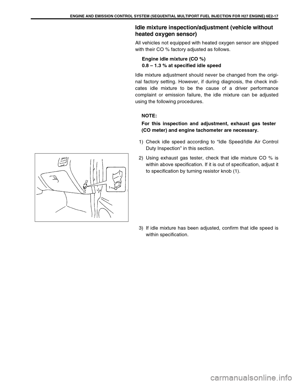
2) Using exhaust gas tester, check that idle mixture CO % is
within above specification. If it is out of specification, adjust it
to specification by turning resistor knob (1).
3) If idle mixture has been adjusted, confirm that idle speed is
within specification. NOTE:
For this inspection and adjustment, exhaust gas tester
(CO meter) and engine tachometer are necessary.
Page 353 of 656
6E2-20 ENGINE AND EMISSION CONTROL SYSTEM (SEQUENTIAL MULTIPORT FUEL INJECTION FOR H27 ENGINE)
CLEANING
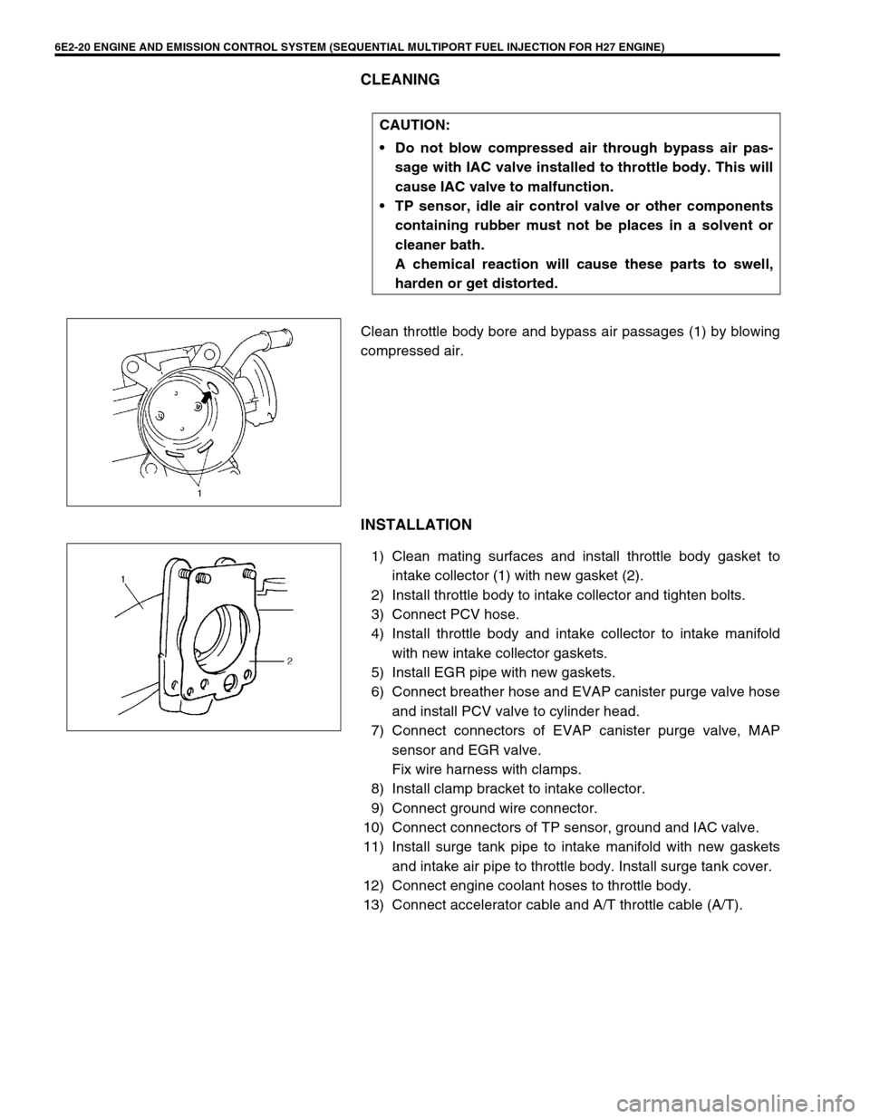
Clean throttle body bore and bypass air passages (1) by blowing
compressed air.
INSTALLATION
1) Clean mating surfaces and install throttle body gasket to
intake collector (1) with new gasket (2).
2) Install throttle body to intake collector and tighten bolts.
3) Connect PCV hose.
4) Install throttle body and intake collector to intake manifold
with new intake collector gaskets.
5) Install EGR pipe with new gaskets.
6) Connect breather hose and EVAP canister purge valve hose
and install PCV valve to cylinder head.
7) Connect connectors of EVAP canister purge valve, MAP
sensor and EGR valve.
Fix wire harness with clamps.
8) Install clamp bracket to intake collector.
9) Connect ground wire connector.
10) Connect connectors of TP sensor, ground and IAC valve.
11) Install surge tank pipe to intake manifold with new gaskets
and intake air pipe to throttle body. Install surge tank cover.
12) Connect engine coolant hoses to throttle body.
13) Connect accelerator cable and A/T throttle cable (A/T).CAUTION:
Do not blow compressed air through bypass air pas-
sage with IAC valve installed to throttle body. This will
cause IAC valve to malfunction.
TP sensor, idle air control valve or other components
containing rubber must not be places in a solvent or
cleaner bath.
A chemical reaction will cause these parts to swell,
harden or get distorted.
Page 354 of 656
ENGINE AND EMISSION CONTROL SYSTEM (SEQUENTIAL MULTIPORT FUEL INJECTION FOR H27 ENGINE) 6E2-21
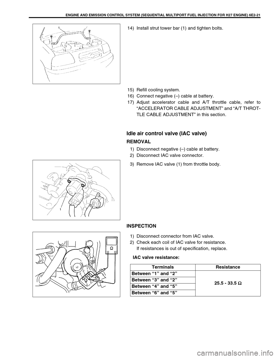
14) Install strut tower bar (1) and tighten bolts.
15) Refill cooling system.
16) Connect negative (–) cable at battery.
17) Adjust accelerator cable and A/T throttle cable, refer to
“ACCELERATOR CABLE ADJUSTMENT” and “A/T THROT-
TLE CABLE ADJUSTMENT” in this section.
Idle air control valve (IAC valve)
REMOVAL
1) Disconnect negative (–) cable at battery.
2) Disconnect IAC valve connector.
3) Remove IAC valve (1) from throttle body.
INSPECTION
1) Disconnect connector from IAC valve.
2) Check each coil of IAC valve for resistance.
If resistances is out of specification, replace.
IAC valve resistance:
Terminals Resistance
Between “1” and “2”
25.5 - 33.5 Ω
ΩΩ Ω Between “3” and “2”
Between “4” and “5”
Between “6” and “5”
Page 355 of 656
6E2-22 ENGINE AND EMISSION CONTROL SYSTEM (SEQUENTIAL MULTIPORT FUEL INJECTION FOR H27 ENGINE)
3) Remove air cleaner outlet hose and remove IAC valve from
throttle body.
4) Connect connector to IAC valve.
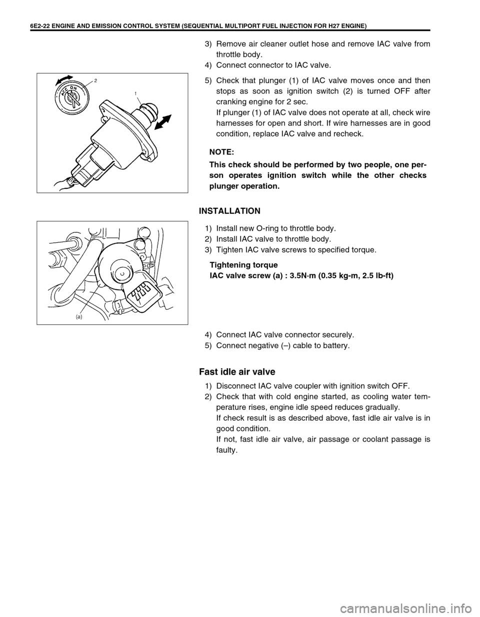
5) Check that plunger (1) of IAC valve moves once and then
stops as soon as ignition switch (2) is turned OFF after
cranking engine for 2 sec.
If plunger (1) of IAC valve does not operate at all, check wire
harnesses for open and short. If wire harnesses are in good
condition, replace IAC valve and recheck.
INSTALLATION
1) Install new O-ring to throttle body.
2) Install IAC valve to throttle body.
3) Tighten IAC valve screws to specified torque.
Tightening torque
IAC valve screw (a) : 3.5N·m (0.35 kg-m, 2.5 lb-ft)
4) Connect IAC valve connector securely.
5) Connect negative (–) cable to battery.
Fast idle air valve
1) Disconnect IAC valve coupler with ignition switch OFF.
2) Check that with cold engine started, as cooling water tem-
perature rises, engine idle speed reduces gradually.
If check result is as described above, fast idle air valve is in
good condition.
If not, fast idle air valve, air passage or coolant passage is
faulty. NOTE:
This check should be performed by two people, one per-
son operates ignition switch while the other checks
plunger operation.
Page 365 of 656

6E2-32 ENGINE AND EMISSION CONTROL SYSTEM (SEQUENTIAL MULTIPORT FUEL INJECTION FOR H27 ENGINE)
Mass air flow sensor (MAF sensor)
INSPECTION
1) Connect voltmeter (1) to “B+” terminal of MAF sensor (2)
coupler disconnected and ground (3).
2) Turn ignition switch ON and check that voltage is battery volt-
age.If not, check if wire harness is open or connection is
poor.
3) Turn ignition switch OFF and remove ECM/PCM cover (1)
from bracket.
4) Connect MAF sensor coupler to MAF sensor.
5) Turn ignition switch ON and check voltage at MAF sensor
output terminal of ECM/PCM connector (1).
MAF sensor output voltage
Voltage: 1.0 - 1.6 V
6) Start engine and check that voltage is lower than 5 V and it
rises as engine speed increases.
(Reference data: 1.7 – 2.0 V at specified idle speed)
If check result is not as specified above, cause may lie in
wire harness, coupler connection, MAF sensor or ECM/
PCM. NOTE:
Use voltmeter with high-impedance (10 kΩ
ΩΩ Ω/V minimum)
or digital type voltmeter.
Page 379 of 656
6E2-46 ENGINE AND EMISSION CONTROL SYSTEM (SEQUENTIAL MULTIPORT FUEL INJECTION FOR H27 ENGINE)
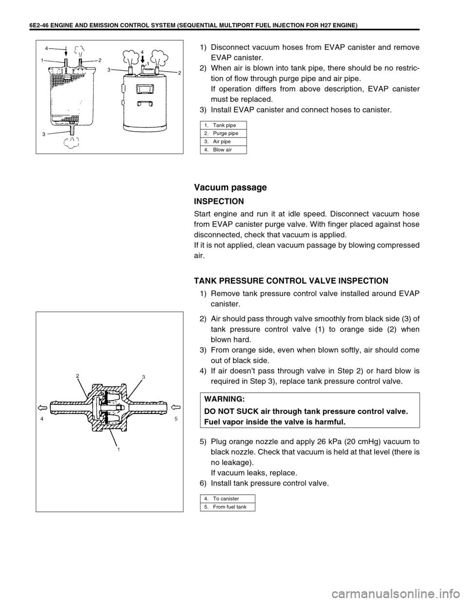
1) Disconnect vacuum hoses from EVAP canister and remove
EVAP canister.
2) When air is blown into tank pipe, there should be no restric-
tion of flow through purge pipe and air pipe.
If operation differs from above description, EVAP canister
must be replaced.
3) Install EVAP canister and connect hoses to canister.
Vacuum passage
INSPECTION
Start engine and run it at idle speed. Disconnect vacuum hose
from EVAP canister purge valve. With finger placed against hose
disconnected, check that vacuum is applied.
If it is not applied, clean vacuum passage by blowing compressed
air.
TANK PRESSURE CONTROL VALVE INSPECTION
1) Remove tank pressure control valve installed around EVAP
canister.
2) Air should pass through valve smoothly from black side (3) of
tank pressure control valve (1) to orange side (2) when
blown hard.
3) From orange side, even when blown softly, air should come
out of black side.
4) If air doesn’t pass through valve in Step 2) or hard blow is
required in Step 3), replace tank pressure control valve.
5) Plug orange nozzle and apply 26 kPa (20 cmHg) vacuum to
black nozzle. Check that vacuum is held at that level (there is
no leakage).
If vacuum leaks, replace.
6) Install tank pressure control valve.
1. Tank pipe
2. Purge pipe
3. Air pipe
4. Blow air
WARNING:
DO NOT SUCK air through tank pressure control valve.
Fuel vapor inside the valve is harmful.
4. To canister
5. From fuel tank