section 7D SUZUKI GRAND VITARA 2001 2.G Owner's Manual
[x] Cancel search | Manufacturer: SUZUKI, Model Year: 2001, Model line: GRAND VITARA, Model: SUZUKI GRAND VITARA 2001 2.GPages: 656, PDF Size: 14.31 MB
Page 54 of 656
AIR CONDITIONING (OPTIONAL) 1B-29
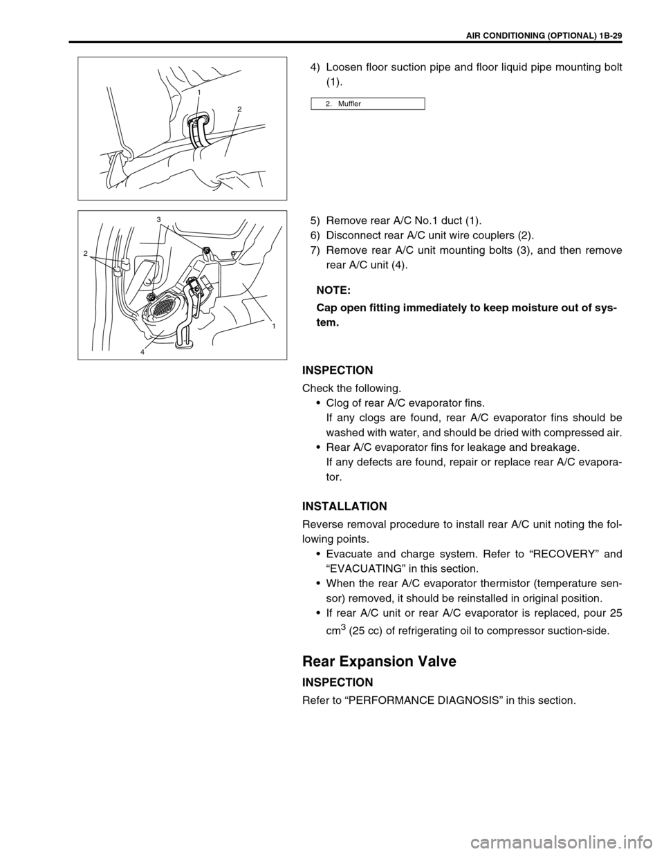
4) Loosen floor suction pipe and floor liquid pipe mounting bolt
(1).
5) Remove rear A/C No.1 duct (1).
6) Disconnect rear A/C unit wire couplers (2).
7) Remove rear A/C unit mounting bolts (3), and then remove
rear A/C unit (4).
INSPECTION
Check the following.
Clog of rear A/C evaporator fins.
If any clogs are found, rear A/C evaporator fins should be
washed with water, and should be dried with compressed air.
Rear A/C evaporator fins for leakage and breakage.
If any defects are found, repair or replace rear A/C evapora-
tor.
INSTALLATION
Reverse removal procedure to install rear A/C unit noting the fol-
lowing points.
Evacuate and charge system. Refer to “RECOVERY” and
“EVACUATING” in this section.
When the rear A/C evaporator thermistor (temperature sen-
sor) removed, it should be reinstalled in original position.
If rear A/C unit or rear A/C evaporator is replaced, pour 25
cm
3 (25 cc) of refrigerating oil to compressor suction-side.
Rear Expansion Valve
INSPECTION
Refer to “PERFORMANCE DIAGNOSIS” in this section.
2. Muffler
1
2
NOTE:
Cap open fitting immediately to keep moisture out of sys-
tem.
23
1
4
Page 55 of 656
1B-30 AIR CONDITIONING (OPTIONAL)
REMOVAL
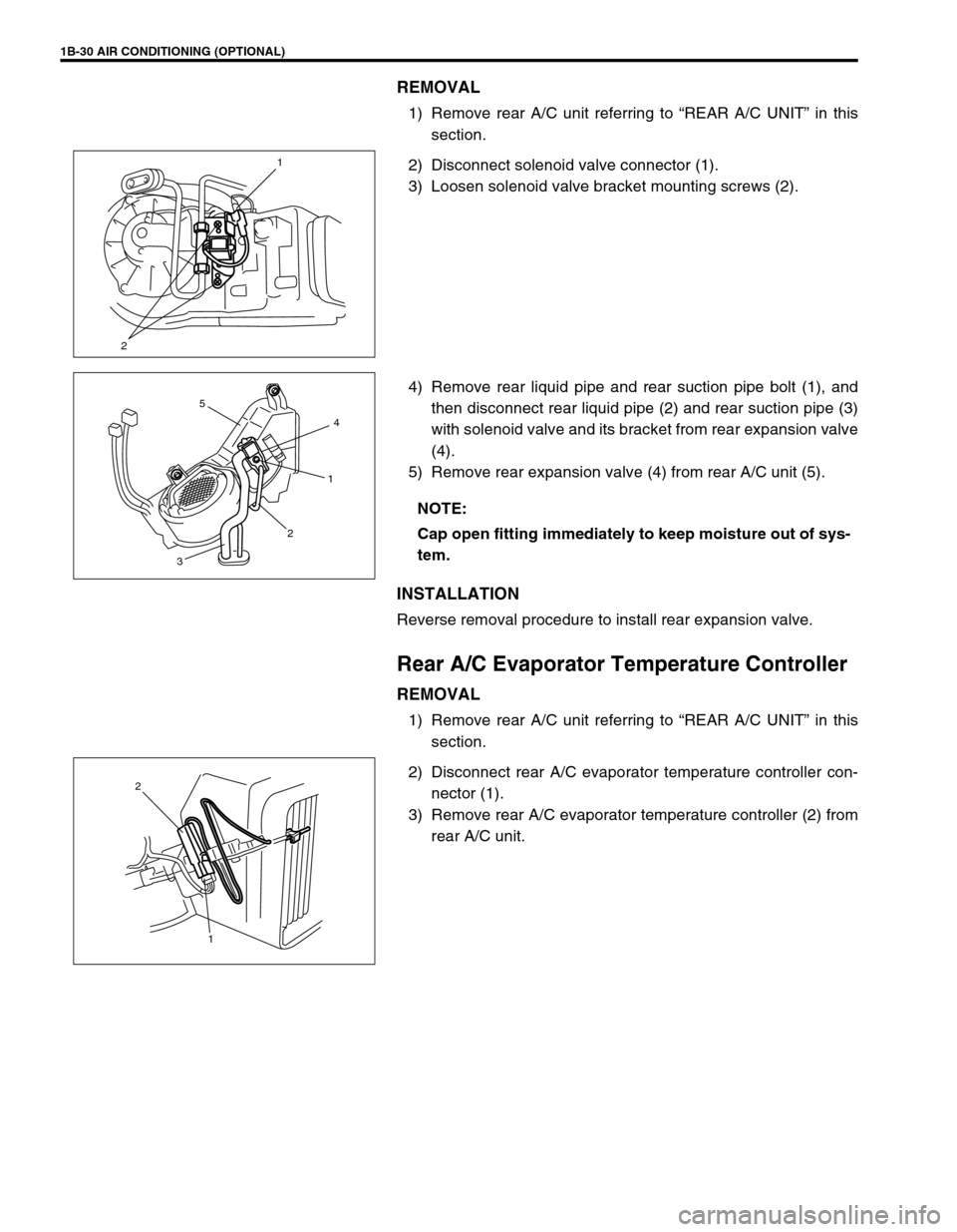
1) Remove rear A/C unit referring to “REAR A/C UNIT” in this
section.
2) Disconnect solenoid valve connector (1).
3) Loosen solenoid valve bracket mounting screws (2).
4) Remove rear liquid pipe and rear suction pipe bolt (1), and
then disconnect rear liquid pipe (2) and rear suction pipe (3)
with solenoid valve and its bracket from rear expansion valve
(4).
5) Remove rear expansion valve (4) from rear A/C unit (5).
INSTALLATION
Reverse removal procedure to install rear expansion valve.
Rear A/C Evaporator Temperature Controller
REMOVAL
1) Remove rear A/C unit referring to “REAR A/C UNIT” in this
section.
2) Disconnect rear A/C evaporator temperature controller con-
nector (1).
3) Remove rear A/C evaporator temperature controller (2) from
rear A/C unit.
21
NOTE:
Cap open fitting immediately to keep moisture out of sys-
tem.
4
1
2
3
5
1 2
Page 56 of 656
AIR CONDITIONING (OPTIONAL) 1B-31
INSPECTION
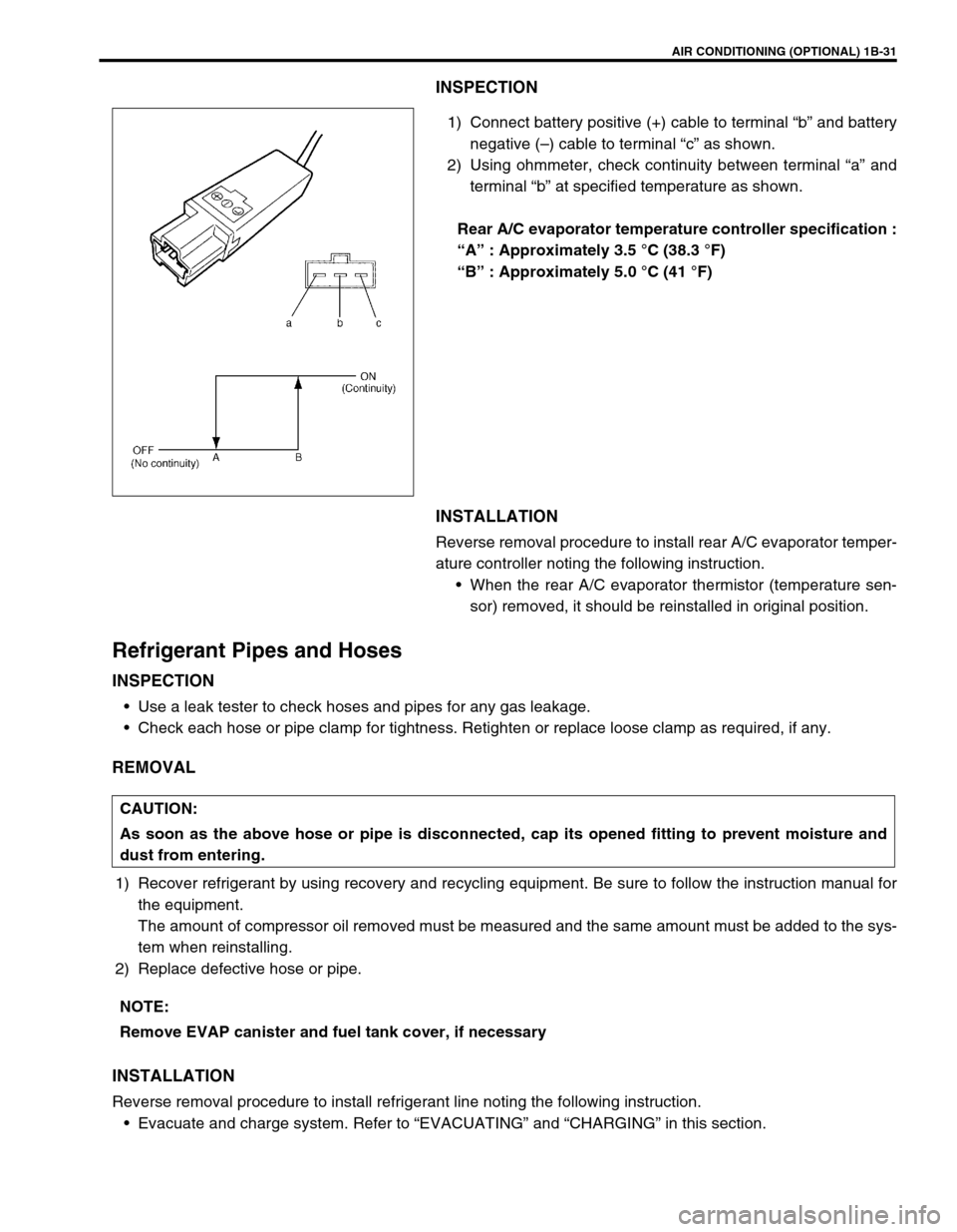
1) Connect battery positive (+) cable to terminal “b” and battery
negative (–) cable to terminal “c” as shown.
2) Using ohmmeter, check continuity between terminal “a” and
terminal “b” at specified temperature as shown.
Rear A/C evaporator temperature controller specification :
“A” : Approximately 3.5 °C (38.3 °F)
“B” : Approximately 5.0 °C (41 °F)
INSTALLATION
Reverse removal procedure to install rear A/C evaporator temper-
ature controller noting the following instruction.
When the rear A/C evaporator thermistor (temperature sen-
sor) removed, it should be reinstalled in original position.
Refrigerant Pipes and Hoses
INSPECTION
Use a leak tester to check hoses and pipes for any gas leakage.
Check each hose or pipe clamp for tightness. Retighten or replace loose clamp as required, if any.
REMOVAL
1) Recover refrigerant by using recovery and recycling equipment. Be sure to follow the instruction manual for
the equipment.
The amount of compressor oil removed must be measured and the same amount must be added to the sys-
tem when reinstalling.
2) Replace defective hose or pipe.
INSTALLATION
Reverse removal procedure to install refrigerant line noting the following instruction.
Evacuate and charge system. Refer to “EVACUATING” and “CHARGING” in this section.
CAUTION:
As soon as the above hose or pipe is disconnected, cap its opened fitting to prevent moisture and
dust from entering.
NOTE:
Remove EVAP canister and fuel tank cover, if necessary
Page 57 of 656
1B-32 AIR CONDITIONING (OPTIONAL)
Solenoid Valve
REMOVAL
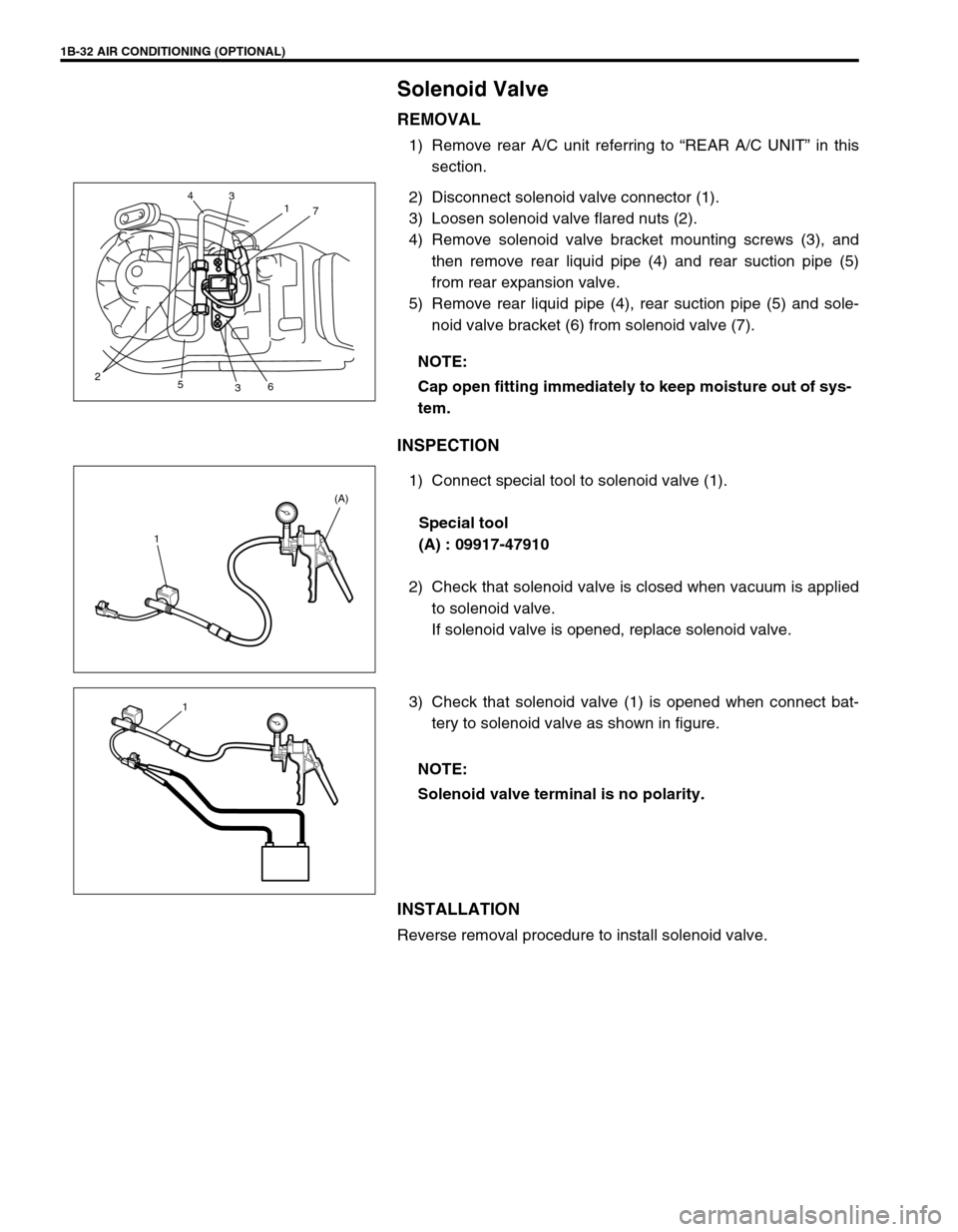
1) Remove rear A/C unit referring to “REAR A/C UNIT” in this
section.
2) Disconnect solenoid valve connector (1).
3) Loosen solenoid valve flared nuts (2).
4) Remove solenoid valve bracket mounting screws (3), and
then remove rear liquid pipe (4) and rear suction pipe (5)
from rear expansion valve.
5) Remove rear liquid pipe (4), rear suction pipe (5) and sole-
noid valve bracket (6) from solenoid valve (7).
INSPECTION
1) Connect special tool to solenoid valve (1).
Special tool
(A) : 09917-47910
2) Check that solenoid valve is closed when vacuum is applied
to solenoid valve.
If solenoid valve is opened, replace solenoid valve.
3) Check that solenoid valve (1) is opened when connect bat-
tery to solenoid valve as shown in figure.
INSTALLATION
Reverse removal procedure to install solenoid valve.NOTE:
Cap open fitting immediately to keep moisture out of sys-
tem.
2
5
367 1 3 4
1(A)
NOTE:
Solenoid valve terminal is no polarity.
1
Page 58 of 656
AIR CONDITIONING (OPTIONAL) 1B-33
Rear Blower Motor Assembly
REMOVAL
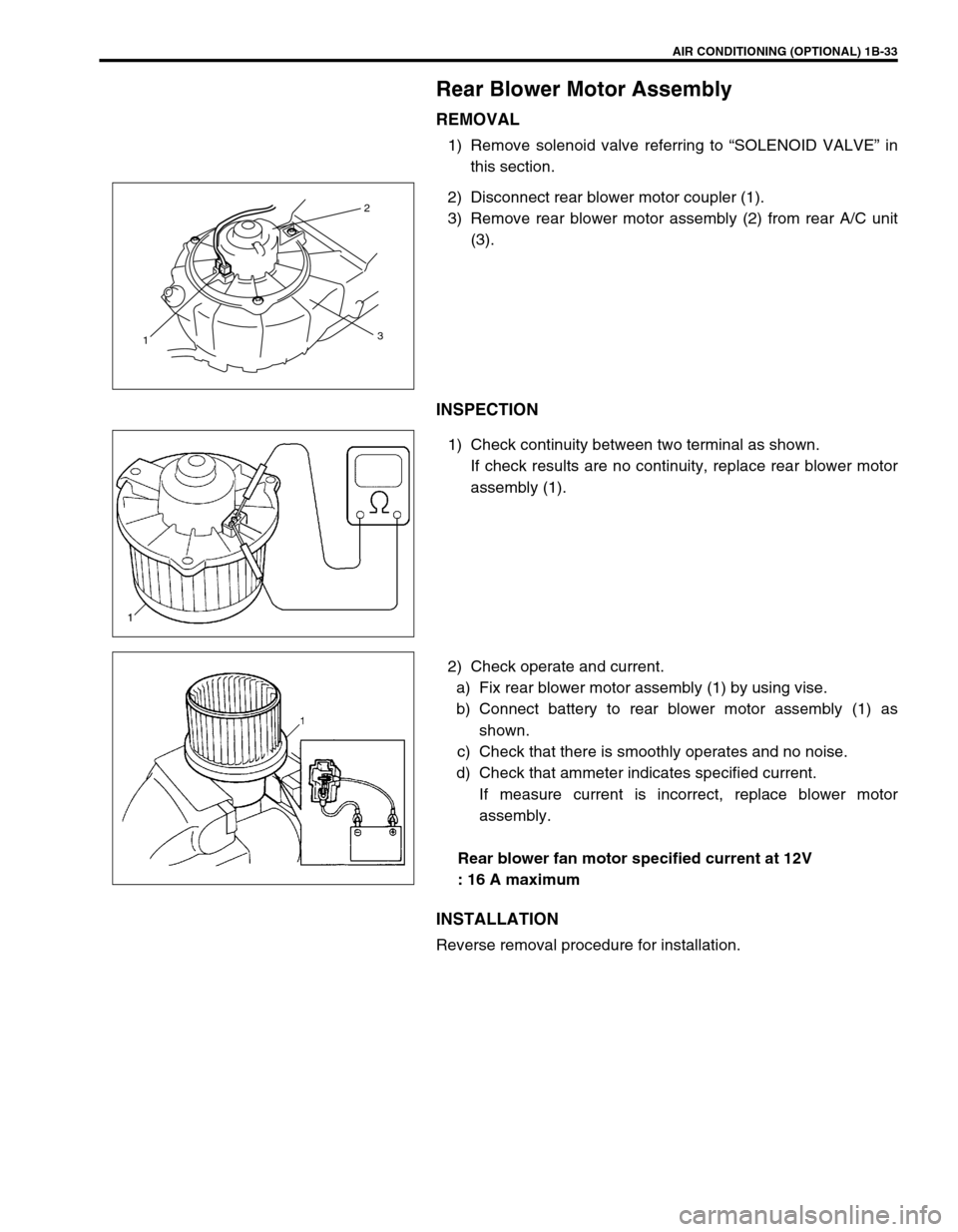
1) Remove solenoid valve referring to “SOLENOID VALVE” in
this section.
2) Disconnect rear blower motor coupler (1).
3) Remove rear blower motor assembly (2) from rear A/C unit
(3).
INSPECTION
1) Check continuity between two terminal as shown.
If check results are no continuity, replace rear blower motor
assembly (1).
2) Check operate and current.
a) Fix rear blower motor assembly (1) by using vise.
b) Connect battery to rear blower motor assembly (1) as
shown.
c) Check that there is smoothly operates and no noise.
d) Check that ammeter indicates specified current.
If measure current is incorrect, replace blower motor
assembly.
Rear blower fan motor specified current at 12V
: 16 A maximum
INSTALLATION
Reverse removal procedure for installation.
2
3
1
Page 60 of 656
AIR CONDITIONING (OPTIONAL) 1B-35
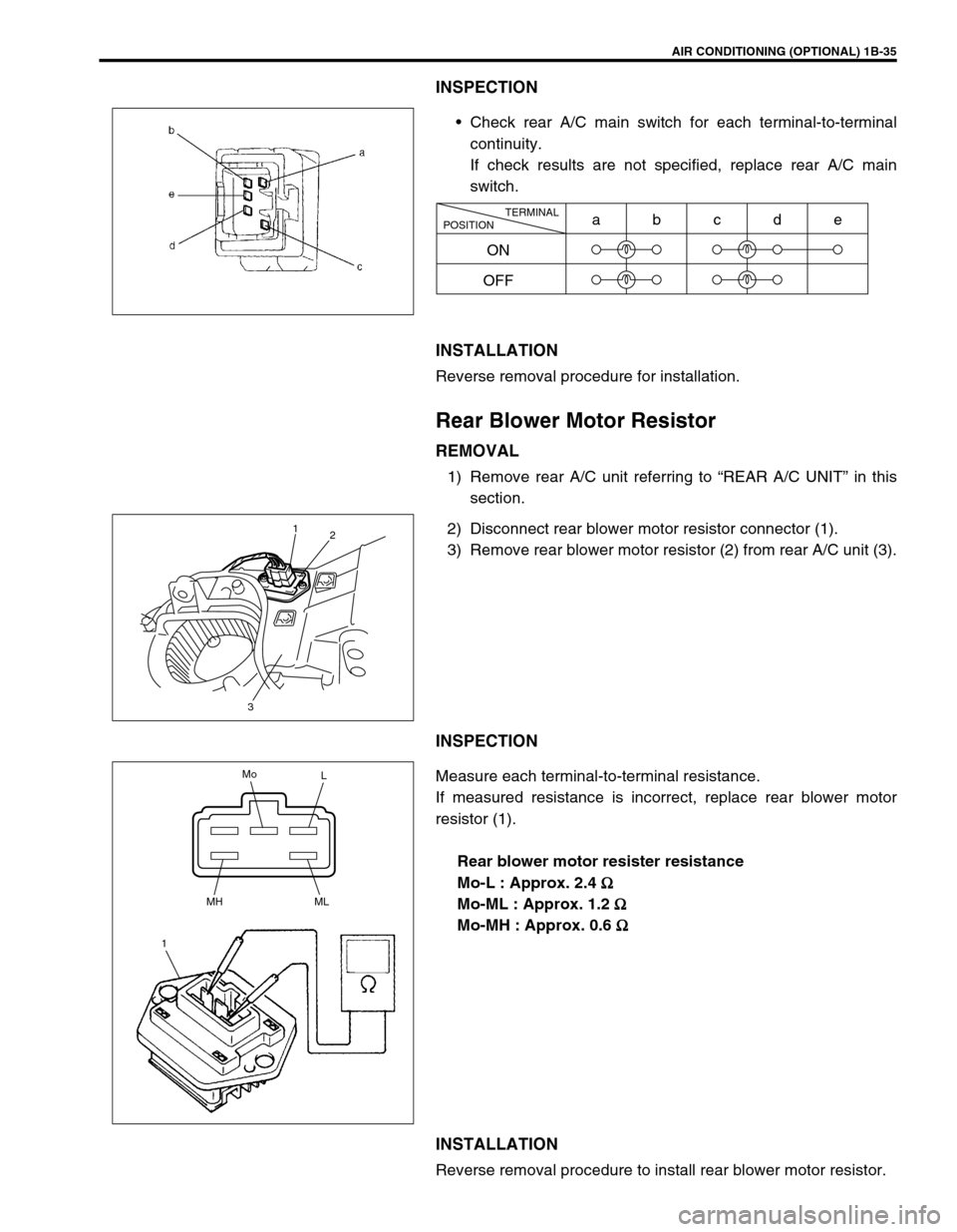
INSPECTION
Check rear A/C main switch for each terminal-to-terminal
continuity.
If check results are not specified, replace rear A/C main
switch.
INSTALLATION
Reverse removal procedure for installation.
Rear Blower Motor Resistor
REMOVAL
1) Remove rear A/C unit referring to “REAR A/C UNIT” in this
section.
2) Disconnect rear blower motor resistor connector (1).
3) Remove rear blower motor resistor (2) from rear A/C unit (3).
INSPECTION
Measure each terminal-to-terminal resistance.
If measured resistance is incorrect, replace rear blower motor
resistor (1).
Rear blower motor resister resistance
Mo-L : Approx. 2.4
Ω
ΩΩ Ω
Mo-ML : Approx. 1.2
Ω
ΩΩ Ω
Mo-MH : Approx. 0.6
Ω
ΩΩ Ω
INSTALLATION
Reverse removal procedure to install rear blower motor resistor.
TERMINAL
POSITION
ON
OFFabcde
1
2
3
Mo
L
MH
1ML
Page 62 of 656
AIR CONDITIONING (OPTIONAL) 1B-37
Rear A/C No.1 and No.2 Duct
Rear A/C No.1 duct
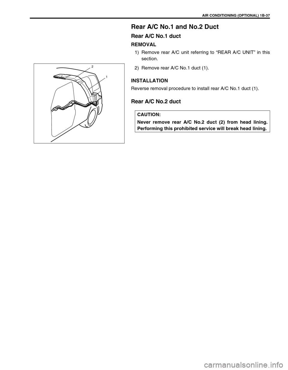
REMOVAL
1) Remove rear A/C unit referring to “REAR A/C UNIT” in this
section.
2) Remove rear A/C No.1 duct (1).
INSTALLATION
Reverse removal procedure to install rear A/C No.1 duct (1).
Rear A/C No.2 duct
CAUTION:
Never remove rear A/C No.2 duct (2) from head lining.
Performing this prohibited service will break head lining.
1
2
Page 64 of 656
AIR CONDITIONING (OPTIONAL) 1B-39
REMOVAL
1) Run engine at idle with A/C ON for 10 minutes.
2) Disconnect negative (–) cable at battery.
3) Recover refrigerant from refrigeration system using recovery
and recycling equipment.
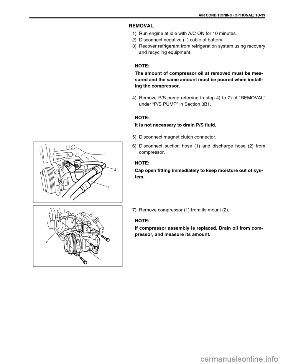
4) Remove P/S pump referring to step 4) to 7) of “REMOVAL”
under “P/S PUMP” in Section 3B1.
5) Disconnect magnet clutch connector.
6) Disconnect suction hose (1) and discharge hose (2) from
compressor.
7) Remove compressor (1) from its mount (2).NOTE:
The amount of compressor oil at removed must be mea-
sured and the same amount must be poured when install-
ing the compressor.
NOTE:
It is not necessary to drain P/S fluid.
NOTE:
Cap open fitting immediately to keep moisture out of sys-
tem.
2
1
NOTE:
If compressor assembly is replaced. Drain oil from com-
pressor, and measure its amount.
1 2
Page 65 of 656
1B-40 AIR CONDITIONING (OPTIONAL)
INSTALLATION
Reverse removal procedure to install compressor assembly not-
ing the following instructions.
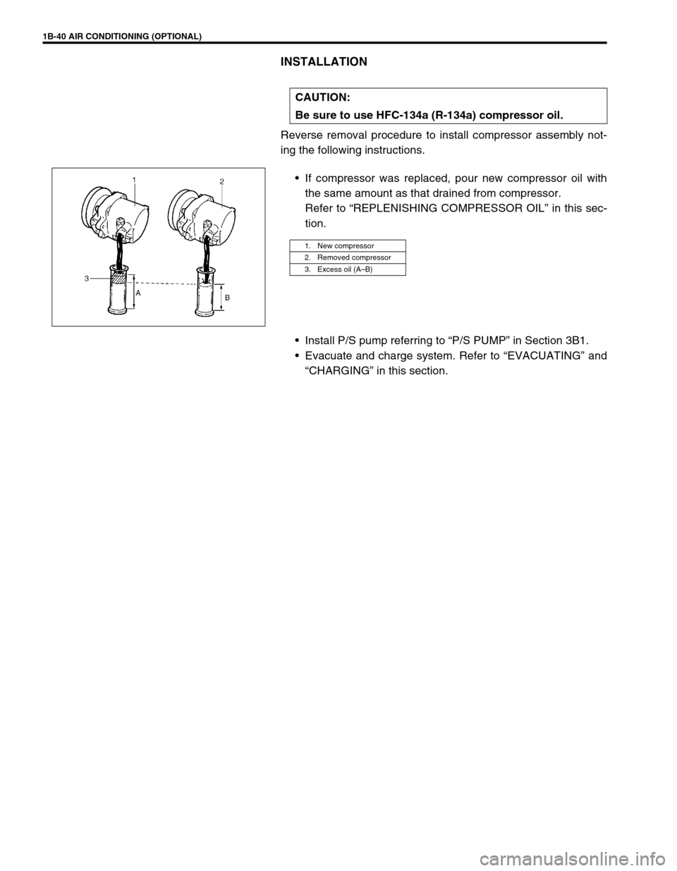
If compressor was replaced, pour new compressor oil with
the same amount as that drained from compressor.
Refer to “REPLENISHING COMPRESSOR OIL” in this sec-
tion.
Install P/S pump referring to “P/S PUMP” in Section 3B1.
Evacuate and charge system. Refer to “EVACUATING” and
“CHARGING” in this section. CAUTION:
Be sure to use HFC-134a (R-134a) compressor oil.
1. New compressor
2. Removed compressor
3. Excess oil (A–B)
Page 66 of 656
AIR CONDITIONING (OPTIONAL) 1B-41
Magnet Clutch
INSPECTION
Check the following items.
Check no sigh of compressor oil leakage
Check magnet clutch pulley bearing for noise and grease
leakage.
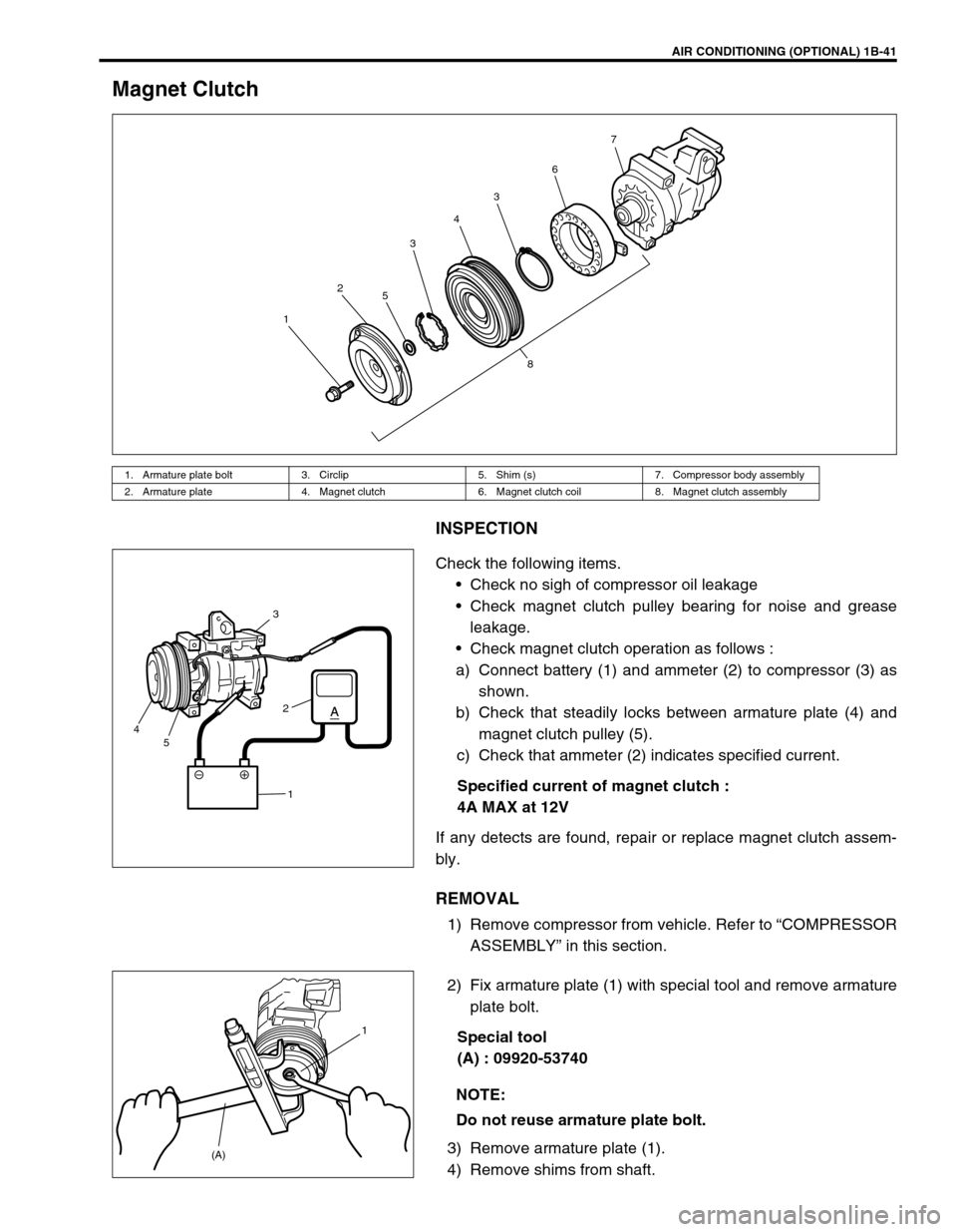
Check magnet clutch operation as follows :
a) Connect battery (1) and ammeter (2) to compressor (3) as
shown.
b) Check that steadily locks between armature plate (4) and
magnet clutch pulley (5).
c) Check that ammeter (2) indicates specified current.
Specified current of magnet clutch :
4A MAX at 12V
If any detects are found, repair or replace magnet clutch assem-
bly.
REMOVAL
1) Remove compressor from vehicle. Refer to “COMPRESSOR
ASSEMBLY” in this section.
2) Fix armature plate (1) with special tool and remove armature
plate bolt.
Special tool
(A) : 09920-53740
3) Remove armature plate (1).
4) Remove shims from shaft.
1. Armature plate bolt 3. Circlip 5. Shim (s) 7. Compressor body assembly
2. Armature plate 4. Magnet clutch 6. Magnet clutch coil 8. Magnet clutch assembly
1234367
5
8
3
2
1 5 4
NOTE:
Do not reuse armature plate bolt.
(A)1