diagram SUZUKI GRAND VITARA 2001 2.G Manual PDF
[x] Cancel search | Manufacturer: SUZUKI, Model Year: 2001, Model line: GRAND VITARA, Model: SUZUKI GRAND VITARA 2001 2.GPages: 656, PDF Size: 14.31 MB
Page 617 of 656
10B-40 AIR BAG SYSTEM
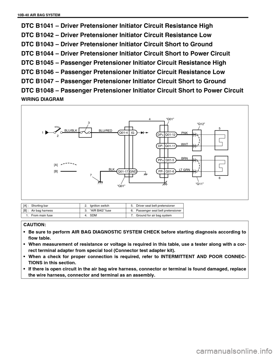
DTC B1041 – Driver Pretensioner Initiator Circuit Resistance High
DTC B1042 – Driver Pretensioner Initiator Circuit Resistance Low
DTC B1043 – Driver Pretensioner Initiator Circuit Short to Ground
DTC B1044 – Driver Pretensioner Initiator Circuit Short to Power Circuit
DTC B1045 – Passenger Pretensioner Initiator Circuit Resistance High
DTC B1046 – Passenger Pretensioner Initiator Circuit Resistance Low
DTC B1047 – Passenger Pretensioner Initiator Circuit Short to Ground
DTC B1048 – Passenger Pretensioner Initiator Circuit Short to Power Circuit
WIRING DIAGRAM
[A] : Shorting bar 2. Ignition switch 5. Driver seat belt pretensioner
[B] : Air bag harness 3.“AIR BAG” fuse 6. Passenger seat belt pretensioner
1. From main fuse 4. SDM 7. Ground for air bag system
PNK
WHT
BRN
LT GRN
“Q11” “Q12”
Q01-12
Q01-11
Q01-5
Q01-6 PP- PP+ DP- DP+
“Q01”
5
6 [A]
[B]1
2BLU/BLK
BLU/RED
3
7
BLK
“Q01” Q01-4
Q01-17IG
GND4
CAUTION:
Be sure to perform AIR BAG DIAGNOSTIC SYSTEM CHECK before starting diagnosis according to
flow table.
When measurement of resistance or voltage is required in this table, use a tester along with a cor-
rect terminal adapter from special tool (Connector test adapter kit).
When a check for proper connection is required, refer to INTERMITTENT AND POOR CONNEC-
TIONS in this section.
If there is open circuit in the air bag wire harness, connector or terminal is found damaged, replace
the wire harness, connector and terminal as an assembly.
Page 624 of 656
AIR BAG SYSTEM 10B-47
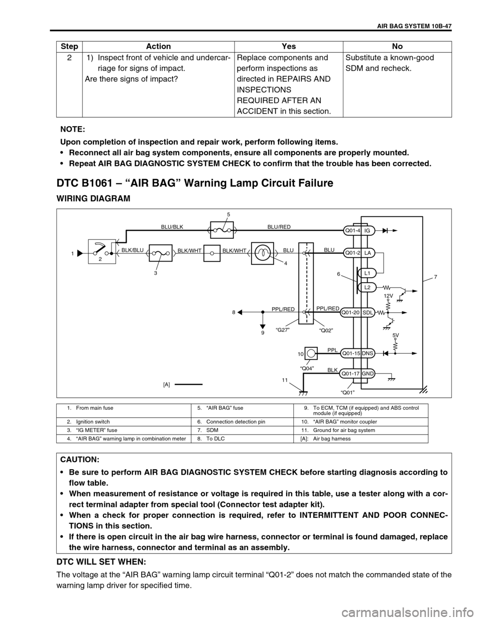
DTC B1061 – “AIR BAG” Warning Lamp Circuit Failure
WIRING DIAGRAM
DTC WILL SET WHEN:
The voltage at the “AIR BAG” warning lamp circuit terminal “Q01-2” does not match the commanded state of the
warning lamp driver for specified time.2 1) Inspect front of vehicle and undercar-
riage for signs of impact.
Are there signs of impact?Replace components and
perform inspections as
directed in REPAIRS AND
INSPECTIONS
REQUIRED AFTER AN
ACCIDENT in this section.Substitute a known-good
SDM and recheck. Step Action Yes No
NOTE:
Upon completion of inspection and repair work, perform following items.
Reconnect all air bag system components, ensure all components are properly mounted.
Repeat AIR BAG DIAGNOSTIC SYSTEM CHECK to confirm that the trouble has been corrected.
1. From main fuse 5.“AIR BAG” fuse 9. To ECM, TCM (if equipped) and ABS control
module (if equipped)
2. Ignition switch 6. Connection detection pin 10.“AIR BAG” monitor coupler
3.“IG METER” fuse 7. SDM 11. Ground for air bag system
4.“AIR BAG” warning lamp in combination meter 8. To DLC [A]: Air bag harness
1
2
34 BLK/BLUBLU/BLK BLU/RED
BLK/WHT BLK/WHTBLUBLU
6
PPL/REDPPL/RED
8
9
10
11
PPL
BLK
“Q04”
“Q01”
Q01-2
Q01-20
Q01-15
Q01-17L1
L2
SDL
DNS
GNDLA
Q01-4
IG
7
[A]
12V
5V
“G27”“Q02”
5
CAUTION:
Be sure to perform AIR BAG DIAGNOSTIC SYSTEM CHECK before starting diagnosis according to
flow table.
When measurement of resistance or voltage is required in this table, use a tester along with a cor-
rect terminal adapter from special tool (Connector test adapter kit).
When a check for proper connection is required, refer to INTERMITTENT AND POOR CONNEC-
TIONS in this section.
If there is open circuit in the air bag wire harness, connector or terminal is found damaged, replace
the wire harness, connector and terminal as an assembly.